Efficient Routing Approach of Network Infrastructure for a Private Organization
BY
Shuvro Sujoy Biswas ID: 141-25-363
This Report Presented in Partial Fulfillment of the Requirements for the Degree of Master of Science in Computer Science and Engineering.
Supervised By
Mr. Narayan Ranjan Chakraborty Sr. Lecturer
Department of CSE Daffodil International University
DAFFODIL INTERNATIONAL UNIVERSITY
DHAKA, BANGLADESH APRIL 2015
©Daffodil International University i
APPROVAL
This Project titled “Efficient Routing Approach of Network Infrastructure for a Private Organization”, submitted by Shuvro Sujoy Biswas to the Department of Computer Science and Engineering, Daffodil International University, has been accepted as satisfactory for the partial fulfillment of the requirements for the degree of M.Sc. in CSE and approved as to its style and contents. The presentation has been held on April 21, 2015.
BOARD OF EXAMINERS
Dr Syed Akhter Hossain Chairman
Professor and Head
Department of Computer Science and Engineering Faculty of Science & Information Technology Daffodil International University
Dr Sheak Rashed Haider Noori Internal Examiner
Asstt. Professor
Department of Computer Science and Engineering Faculty of Science & Information Technology Daffodil International University
A.H.M. Saiful Islam Internal Examiner
Asstt. Professor
Department of Computer Science and Engineering Faculty of Science & Information Technology Daffodil International University
Dr Muhammad Shorif Uddin External Examiner
Professor and Chairperson
Department of Computer Science and Engineering Jahagirnagar University
©Daffodil International University ii
DECLARATION
I hereby declare that, this project has been done by me under the supervision of Mr.
Narayan Ranjan Chakraborty, Sr. Lecturer, Department of CSE Daffodil International University. I also declare that neither this project nor any part of this project has been submitted elsewhere for award of any degree or diploma.
Supervised by:
Mr. Narayan Ranjan Chakraborty Sr. Lecturer
Department of CSE
Daffodil International University
Submitted by:
Shuvro Sujoy Biswas ID: 141-25-363 Department of CSE
Daffodil International University
©Daffodil International University iii
ACKNOWLEDGEMENT
First I express my heartiest thanks and gratefulness to almighty God for His divine blessing makes me possible to complete the final year project successfully.
I really grateful and wish our profound our indebtedness to Mr. Narayan Ranjan Chakraborty, Sr. Lecturer, Department of CSE Daffodil International University, Dhaka. Deep Knowledge & keen interest of our supervisor in the field of “efficient routing & switching” to carry out this project. His endless patience ,scholarly guidance ,continual encouragement , constant and energetic supervision, constructive criticism , valuable advice ,reading many inferior draft and correcting them at all stage have made it possible to complete this project.
I would like to express our heartiest gratitude to Mr. Narayan Ranjan Chakraborty, Sr. Lecturer, Department of CSE and Professor Dr. Syed Akhter Hossain Head, Department of CSE, for his kind help to finish our project and also to other faculty member and the staff of CSE department of Daffodil International University.
I would like to thank our entire course mate in Daffodil International University, who took part in this discuss while completing the course work.
Finally, I must acknowledge with due respect the constant support and patients of our parents.
©Daffodil International University iv
ABSTRACT
Aim of these projects is to develop a network infrastructure for a private organization in Bangladesh. One of the major goals of these projects is to implement subnet concepts to reduce traffic, increase security and extendable network model. Routing protocol is taking a vital role in the modern communication networks. These projects presents a simulation based analysis on EIGRP. The proposed work for these projects is to an IP based network infrastructure has been developed for a renowned private organization in Bangladesh. This network designs in scalable, secured, effective and fault tolerable. LAN and WAN technologies are used and its collision free, full duplex Gigabit &Fast Ethernet switching LANs design is proposed for 1000Mbps
&100Mbps data transmission. Point-to-Point (PPP) authentic link protocol is used for serial connection between routers. Some departments are considered as separate subnets and they are designed by VLAN concepts and this reduces the broadcast traffic using classless (VLSM) IP addressing concept. A single Internet connection (20Mbps) is shown with real IP (200.20.20.62/24) interface at the proposed design.
This network infrastructure design is simulated and tested with Packet Tracer 6.0.1.
Finally the evaluation results show that efficient routing approach of a network infrastructure for a private organization is providing better performance.
©Daffodil International University v
TABLE OF CONTENTS
CONTENTS PAGE
Board of examiners i
Declaration ii
Acknowledgements iii
Abstract iv
CHAPTER
CHAPTER 1: INTRODUCTION
1-21.1 Aim & Objective 1
1.2 Overview of Design
1.3 Chapter Summary 1-2
2
CHAPTER 2: INTERNET PROTOCOL ROUTING
3-82.1 General Overview 3
2.2 Routing Basic
2.3 The IP Routing Process 2.3.1 Configuring IP Routing 2.4 Static Routing
2.4.1 Default Routing
2.4.2 Dynamic Routing
2.4.3 Static vs Dynamic Routing
3-4 4-5 5-6 6-7 7 7 7-8 8
©Daffodil International University vi
CHAPTER 3: PROPOSED NETWORK INFRASTRUCTURE
9-133.1 Making VLSM for Proposed Network 9
3.1.1 Making the Subnetwork 9-10
3.1.2 Subnetting for Data & Voice VLAN Using VLSM 10-12
3.1.3 Making the Serial Connection 13
3.1.4 Implementation for Serial Interface 13
CHAPTER 4: ROUTING OPTIMIZATIONS NETWORKS
14-19 4.1 Routing Protocol Optimization 144.1.1RIP (Routing Information Protocol) 14
4.1.2 Interior Gateway Routing Protocol (IGRP) 14-15 4.1.3 Intermediate System to Intermediate System (IS-IS) 15-16 4.1.4: Open Shortest Path First (OSPF) 16-17 4.1.5 Enhanced Interior Gateway Routing Protocol (EIGRP) 17-18 4.1.6 VLSM Support and Summarization 18-19
CHAPTER 5: CONFIGURE IP PHONE & DIAL PEERS
19-235.1 Configure Cisco IP Phone 7960 & Dial Peers 19
5.1.1 Application (telephony-service) 19
5.1.2 Auto Assign 19-20
5.1.3 Ephone 20
5.1.4 Ephone-dn 20-21
5.2 Understanding Dial Peers 21
©Daffodil International University vii
5.2.1 Configuring POTS Dial Peers 21
5.2.2 Configuring VoIP Dial Peers 21-22
5.2.3 Configuring Destination-Pattern Options 22
5.2.4 Default Dial Peer 22
5.2.5 Matching Inbound Dial Peers 22-23
5.2.6 Matching Outbound Dial Peers 23
CHAPTER 6: CONFIGURATIONS & VARIFICATIONS
24-266.1 Router Configuration 24
6.2 Switch Configuration 24
6.3 DHCP Server 24
6.3.1 Major DHCP Features 24
6.3.2 Configuring DHCP 25
6.3.3 DHCP Operation 25
6.4 Verification, Dial-Up & Testing 26
CHAPTER 7: CONCLUSION
7.1 Conclusion 27
7.2 Limitations 27
7.1 Future Work 27
REFERENCES
28©Daffodil International University viii
LIST OF FIGURES
FIGURES PAGE NO
Figure 1.1: Design of Implemented Network 2
Figure 2.1: A Simple Routing Example 4
Figure 2.2: IP Routing Example Using Two Hosts & One Router Figure 2.3: Configuring IP Routing 4
6
Figure 4.1: OSPF Network Figure 4.2: Network topology of EIGRP Figure 4.3:Discontinuous Network Figure 6.1: DHCP Operation 16
18
18
25
©Daffodil International University ix
LIST OF TABLES
TABLES PAGE NO
Table 3.1: Subnetting Part-1 10
Table 3.2: VLSM Part-1 11
Table 3.3: VLSM Part-2 Table 3.4: VLSM Part-3 12
12
Table 3.5: VLSM Part-4 13
Table 3.6: Implementation For Serial Interface 13
Table 5.1: Syntax Description of Application (telephony-service) 19
Table 5.2: Syntax Description of Auto Assign Table 5.3: Syntax Description of Ephone Tag 20
20
Table 5.4: Syntax Description of Ephone-dn Tag 21
Table 5.5: Step For POTS Dial Peers 21
Table 5.6: Step For VOIP Dial Peers Table 5.7: Step For Outbound Dial Peers 21
23
Table 6.1: Syntax For DHCP Configuration 25
Table 6.2: Verify, Communication & Dial up between various hosts 26
©Daffodil International University 1
Chapter 1 Introduction 1.1 Aim & Objective
Aim of this project is to develop a network infrastructure for a private organization in Bangladesh and finally find out efficient routing approach for the proposed network infrastructure. This is a location based network model. One of the prime goals of this project is to implement subnet concepts to reduce traffic, increase security and extendable network model.
1.2 Overview of Design
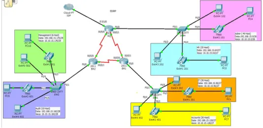
A private organization needs a network to be designed and implemented. The organization has three campuses such as Head Quarter, Branch 1, and Branch 2. All the locations are interconnected with each other. Head Quarter has a large and complex local area network. It has two departments such as Admin & HR. There are 45 hosts in admin department which are bearing data & voice in different sub network. Here data & voice are passing by different VLAN such as 2 & 20 respectively. Some users are also using soft phone. Similarly there are 30 hosts in HR department which are also passing voice & data by VLAN 3 & 30 respectively.
Moreover, there are also two departments in Branch 1 i.e. IT & Accounts. Each department is carrying 30 hosts including IP phone. Data & voice are passing in different VLAN such as 4,5,40 & 50 separately. In Branch 2, Audit & Managements are bearing 10 hosts & 6 hosts individually. Each is passing voice & data separately.
Data & voice are transferring via VLAN such as. 6,7,60 & 70 correspondingly. Due to the size and complexity of the organization need to do VLANs to control broadcast enhance security and logically group users.
The following tasks are required to complete the Network Infrastructure.
Set up the physical layout of the network using the diagram and accompanying narrative.
Correctly configure VLANs and 802.1q trucking.
Correctly configure DHCP.
IP Phone configuration (Physical & Soft phone)
©Daffodil International University 2
Verify that all configurations are operational and functioning according to the scenario guidelines.
Provided detailed documentation in a prescribed form as listed in the deliverables section.
Finally find out efficient routing for the proposed network [14].
Design of implemented network diagram figure-1.1 is shown as bellow.
Figure 1.1: Design of Implemented Network
1.3 Chapter Summary
There are describe objective, overview & of the implemented network in the chapter one. It can be provided definition of routing basic, routing process, IP routing (Static, Dynamic & Default) & differentiate between static vs dynamic routing in chapter two.
Moreover, subnetting is the major part of this project. There are implemented subnetting with VLSM (Variable Length Subnet Mask) as well serial connectivity for all router. Also it has been identified DTE & DCE port in the chapter three. In chapter four, there are explained routing protocol such as RIPv1, RIPv2, IGRP, IS-IS, OSPF, and EIGRP, advantage, disadvantage & Route Summarizations. In the chapter five, it contain basic configuration of IP phone & dial peers by using telephony service, auto assign, ephone, ephone-dn etc. There are represent router & switch configuration, DHCP feature, configuration service operation & testing using packet tracer in the chapter six. Finally it delivered discussion & conclusion in the last part which is bearing chapter seven.
©Daffodil International University 3
Chapter 2
Internet Protocol Routing 2.1 General Overview
IP routing is the process of moving packets from one network to another network using routers. The IP Routing protocols enable routers to build up a forwarding table that correlates final destinations with next hop addresses.
These protocols include:
BGP (Border Gateway Protocol)
IS-IS (Intermediate System - Intermediate System)
OSPF (Open Shortest Path First)
RIP (Routing Information Protocol
A routing protocol is used by routers to dynamically find all the networks in the internetwork and to ensure that all routers have the same routing table. Basically, a routing protocol determines the path of a packet through an internetwork. Examples of routing protocols are RIP, RIPv2, EIGRP, and OSPF.
A routed protocol can be used to send user data (packets) through the established enterprise. Routed protocols are assigned to an interface and determine the method of packet delivery. Examples of routed protocols are IP and IPv6 [13].
2.2 Routing Basics
The term routing is used for taking a packet from one device and sending it through the network to another device on a different network. Routers don’t really care about hosts they only care about networks and the best path to each network [3].
To be able to route packets, a router must know, at a minimum, the following:
Destination address
Neighbor routers from which it can learn about remote networks
©Daffodil International University 4
Possible routes to all remote networks
The best route to each remote network
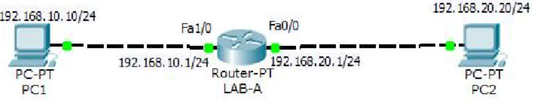
How to maintain and verify routing information A simple routing example is prearranged on the following figure 2.1.
Figure 2.1: A Simple Routing Example
2.3 The IP Routing Process
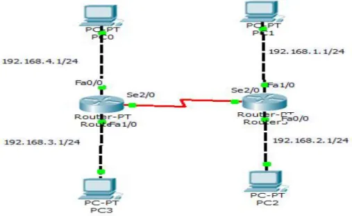
The IP routing process is fairly simple and doesn’t change, regardless of the size of your network. For an example, we’ll use Figure 2.2 to describe step-by-step what happens when PC-1 wants to communicate with PC-2 on a different network [13].
Figure 2.2: IP routing example using two hosts and one router
©Daffodil International University 5
Internet Control Message Protocol (ICMP) creates an echo request payload (which is just the alphabet in the data field).
ICMP hands that payload to Internet Protocol (IP), which then creates a packet. At a minimum, this packet contains an IP source address, an IP destination address, and a Protocol field with 01h.
Once the packet is created, IP determines whether the destination IP address is on the local network or a remote one.
Since IP determines that this is a remote request, the packet needs to be sent to the default gateway so the packet can be routed to the remote network. The Registry in Windows is parsed to find the configured default gateway.
2.3.1 Configuring IP Routing
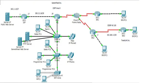
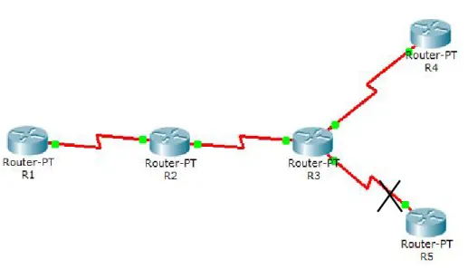
It’s time to get serious and configure a real network! Figure 2.3 shows the following devices
Five routers such as ISP HQ, BR1, BR2& BR3 respectively.
Three servers such as Public Web server, TFTP Web Server & Game Wheel Web Server correspondingly.
Two Cisco Switches & 7960 IP Phone
A access point &
Some PC.
It’s time to get serious and configure a real network. It’s a complete internetwork solution where cloud also connected. As there are also use public IP as well as private IP. Think of the access point as more of a hub than a router. As you might guess, I’ve got quite a nice collection of routers for us to play with.
The first step for this project is to correctly configure each router with an IP address on each Interface. After we go over how the network is configured, I’ll cover how to
©Daffodil International University 6
configure IP routing. Each network figure-2.3 used a 24-bit subnet mask (255.255.255.0), which makes the interesting (subnet) octet the third one [4].
Figure 2.3: Configuring IP Routing
We will discuss about the following types of routing in the following sections:
Static routing
Default routing
Dynamic routing
2.4 Static Routing
Static routing occurs when you manually add routes in each router’s routing table.
There are pros and cons to static routing, but that’s true for all routing processes.
Static routing has the following advantage:
There is no overhead on the router CPU, which means you could possibly buy a cheaper router than you would use if you were using dynamic routing.
There is no bandwidth usage between routers, which means you could possibly save money on WAN links.
©Daffodil International University 7
It adds security because the administrator can choose to allow routing access to certain networks only.
Static routing has the following disadvantages:
The administrator must really understand the internetwork and how each router is connected in order to configure routes correctly.
If a network is added to the internetwork, the administrator has to add a route to it on all routers by hand.
It’s not feasible in large networks because maintaining it would be a full-time job in itself.
2.4.1 Default Routing
This is the method where all routers are configured to send all packets towards a single router. This is a very useful method for small networks or for networks with a single entry and exit point. It is usually used in addition to Static and/or Dynamic routing.
We use default routing to send packets with a remote destination network not in the routing table to the next-hop router. It should only use default routing on stub networks those with only one exit path out of the network [1].
2.4.2 Dynamic Routing
Dynamic routing is when protocols are used to find networks and update routing tables on routers. True, this is easier than using static or default routing, but it’ll cost you in terms of router CPU processes and bandwidth on the network links. A routing protocol defines the set of rules used by a router when it communicates routing information between neighbor routers.
The routing protocol I’m going to talk about in this chapter is Routing Information Protocol (RIP) versions 1 and 2, with a bit of Interior Gateway Routing Protocol (IGRP) thrown in.
©Daffodil International University 8
Two types of routing protocols are used in internetworks: interior gateway protocols (IGPs) and exterior gateway protocols (EGPs). IGPs are used to exchange routing information with routers in the same autonomous system (AS). An AS is a collection of networks under a common administrative domain, which basically means that all routers sharing the same routing table information are in the same AS. EGPs are used to communicate between ASes. An example of an EGP is Border Gateway Protocol (BGP), which is beyond the scope of this book.
Since routing protocols are so essential to dynamic routing, I’m going to give you the basic information you need to know about them next. Later on in this chapter, we’ll focus on configuration [1].
2.4.3 Static versus Dynamic Routing
Static routing is a routing process whose routing table follows a manual construction and fixed routes at boot time. The routing table needs to be updated by the network administrator when a new network is added and discarded in the AS. Static routing is mainly used for small networks. Its performance degrades when the network topology is changed routing. It usually provides more control for the system administrator in order to maintain the whole network. In static routing, the network has more control over the network. It’s simple functionality and less CPU processing time are also an advantage but poor performance experienced when network topology changes, complexity of reconfiguring network topology changes and difficult manual setup procedure are still major drawbacks of static routing.
On the contrary, dynamic routing is a routing protocol in which the routing tables are formed automatically such that the neighboring routers exchange messages with each other. The best route procedure is conducted based on bandwidth, link cost, hop number and delay. The protocol usually updates these values. Dynamic routing protocol has the advantage of shorter time spent by the administrator in maintaining and configuring routes. However it has diversity problems like routing loops and route inconsistency [3].
©Daffodil International University 9
Chapter 3
Proposed Network Infrastructure
3.1 Making VLSM for Proposed Network
Variable-Length Subnet Masks (VLSMs) were developed to allow multiple levels of sub networked IP addresses within a single network. This strategy can be used only when supported by the routing protocol in use, such as Open Shortest Path First (OSPF) and Enhanced Interior Gateway Routing Protocol (EIGRP). RIPv1 is older than VLSM and cannot support it. RIPv2, however, can support VLSM.
VLSM allows an organization to use more than one subnet mask within the same network address space. Implementing VLSM allows an administrator to “subnet a subnet” and maximizes addressing efficiency [1].
3.1.1 Making the Subnetwork
How to Do Subnetting (Rules of Subnetting)
How many subnets? 2x = number of subnets. x is the number of masked bits, or the 1s. For example, in 11000000, the number of 1s gives us 22 subnets. In this example, there are 4 subnets.
How many hosts per subnet? 2y – 2 = number of hosts per subnet. y is the number of unmasked bits or the 0s. For example, in 11000000, the number of 0s gives us 26 – 2 hosts. In this example, there are 62 hosts per subnet. You need to subtract 2 for the subnet address and the broadcast address, which are not valid hosts.
What are the valid subnets/block size? 256 – Subnet mask = block size, or increment number. An example would be 256 – 192 = 64. The block size of a 192 mask is always 64. Start counting at zero in blocks of 64 until you reach the subnet mask value and these are your subnets. 0, 64, 128, 192. Easy, huh?
What’s the broadcast address for each subnet? Now here’s the really easy part.
Since we counted our subnets in the last section as 0, 64, 128, and 192, the broadcast address is always the number right before the next subnet. For
©Daffodil International University 10
example, the 0 subnet has a broadcast address of 63 because the next subnet is 64. The 64 subnet has a broadcast address of 127 because the next subnet is 128. And so on. And remember, the broadcast address of the last subnet is always 255.
What are the valid hosts? Valid hosts are the numbers between the subnets, omitting the all 0s and all 1s. For example, if 64 is the subnet number and 127 is the broadcast address, then 65–126 is the valid host range—it’s always the numbers between the subnet address and the broadcast address [1].
3.1.2 Subnetting for Data & Voice VLAN Using VLSM
Given the network address for data Vlan : 192.168.15.0/24 Given the network address for voice Vlan : 10.10.15.0/24
Proposed network address for data Vlan : 192.168.15.0/26 Proposed network address for voice Vlan : 10.10.15.0/26
Now let’s start:
How many subnets? 22=4
How many hosts per subnet? 26-2=62
What is the valid subnets/ block size? 256-192=64
What is the broadcast address? (Block size-1)=64-1=63
What is the last host? (Broadcast-1)=63-1=62
Subnet Mask = All Network bit set to ‘1’
All Host bit set to ‘0’
= /25 = 11111111.11111111.11111111.11000000 = 255.255.255.192 Table 3.1 Subnetting Part-1
Subnet 0 64 128 192
First Host 1 65 129 193
Last Host 62 126 190 254
Broadcast 63 127 191 255
45 Hosts
©Daffodil International University 11
Number # 1 sub network from table 1.0 for data : 192.168.15.64/27 Number # 1 sub network from table 1.0 for voice : 10.10.15.64/27
Now let’s start:
How many subnets? 23=8
How many hosts per subnet? 25-2=30
What is the valid subnets/ block size? 256-224=32
What is the broadcast address? (Block size-1)=64+32-1=95
What is the last host? (Broadcast-1)=95-1=94
Subnet Mask = All Network bit set to ‘1’
All Host bit set to ‘0’
= /25 = 11111111.11111111.11111111.11100000 = 255.255.255.224
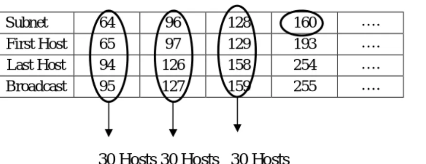
Table 3.2: Vlsm Part-1
Subnet 64 96 128 160 ….
First Host 65 97 129 193 ….
Last Host 94 126 158 254 ….
Broadcast 95 127 159 255 ….
30 Hosts 30 Hosts 30 Hosts
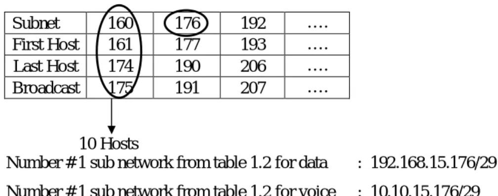
Number # 3 sub network from table 1.1 for data : 192.168.15.160/28 Number # 3 sub network from table 1.1 for voice : 10.10.15.160/28 Now let’s start:
How many subnets? 24=16
How many hosts per subnet? 24-2=14
What is the valid subnets/ block size? 256-240=16
What is the broadcast address? (Block size-1)=160+16-1=175
What is the last host? (Broadcast-1)=175-1=174
Subnet Mask = All Network bit set to ‘1’
All Host bit set to ‘0’
= /25 = 11111111.11111111.11111111.11110000 = 255.255.255.240
©Daffodil International University 12
Table 3.3: Vlsm Part-2
Subnet 160 176 192 ….
First Host 161 177 193 ….
Last Host 174 190 206 ….
Broadcast 175 191 207 ….
10 Hosts
Number # 1 sub network from table 1.2 for data : 192.168.15.176/29 Number # 1 sub network from table 1.2 for voice : 10.10.15.176/29
Now let’s start:
How many subnets? 25=32
How many hosts per subnet? 23-2=6
What is the valid subnets/ block size? 256-248=8
What is the broadcast address? (Block size-1)=176+8-1=183
What is the last host? (Broadcast-1)=183-1=1182
Subnet Mask = All Network bit set to ‘1’
All Host bit set to ‘0’
= /25 = 11111111.11111111.11111111.11111000 = 255.255.255.248 Table 3.4: Vlsm Part-3
Subnet 176 184 192 ….
First Host 177 185 193 ….
Last Host 182 190 198 ….
Broadcast 183 191 199 ….
6 Hosts 6 Hosts
©Daffodil International University 13
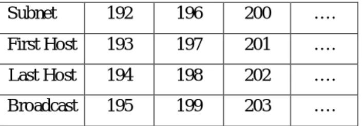
3.1.3 Making the Serial Connection
Subnetwork 192.168.15.192/30 is used for Serial connection. This connection is called Point-to-Point (PPP) connection.
Now let’s start:
How many subnets? 26=64
How many hosts per subnet? 22-2=2
What is the valid subnets/ block size? 256-252=4
What is the broadcast address? (Block size-1)=192+4-1=195
What is the last host? (Broadcast-1)=195-1=194
Subnet Mask = All Network bit set to ‘1’
All Host bit set to ‘0’
= /25 = 11111111.11111111.11111111.11111100 = 255.255.255.252 Table 3.5: Vlsm Part-4
Subnet 192 196 200 ….
First Host 193 197 201 ….
Last Host 194 198 202 ….
Broadcast 195 199 203 ….
3.1.4 Implementation for Serial Interface
Table 3.6: Implementation For Serial Interface
Name Interface Subnet mask HQ S0/0/0 = 192.168.15.193/30
(DCE)
S0/0/1 = 192.168.15.197/30 (DCE)
255.255.255.252 255.255.255.252
Branch 1 S0/0/0 = 192.168.15.202/30 (DTE)
S0/0/1 = 192.168.15.198/30 (DTE)
255.255.255.252 255.255.255.252
Branch 2 S0/0/0 = 192.168.15.194/30 (DTE)
S0/0/1 = 192.168.15.201/30 (DCE)
255.255.255.252 255.255.255.252
©Daffodil International University 14
Chapter 4
Routing Optimization for Networks 4.1 Routing Protocol Optimization
Protocol Independent Route Optimization (PIRO) introduced the ability of Performance Routing (PfR) to search for a parent route--an exact matching route, or a less specific route--in the IP Routing Information Base (RIB), allowing PfR to be deployed in any IP-routed environment including Interior Gateway Protocols (IGPs) such as OSPF and IS-IS.
4.1.1: RIP (Routing Information Protocol)
Routing Information Protocol (RIP) is one of the first protocols to be used in networking and is classified as a distance vector routing protocol. RIP uses broadcast User Datagram Protocol (UDP) data packets to exchange routing information. There are two versions RIPv1 & RIPv2.
RIP Version1 is the original version and has many limitations. The metric that RIP uses to rate the value of different routes is hop count. The hop count metric works by assigning static routes with a value of 0 and all other routers values are set by the number of hops (up to 15) that the data must travel though to get to an end point.
RIP Version 2 supports plain text and MD5 authentication, route Summarization, classless inter-domain routing (CIDR), variable-length subnet masks (VLSMs), Multicast support. Some vendors support other non-standard features for RIP but be careful as many vendor centric features are not compatible in a mixed vendor network.
4.1.2 Interior Gateway Routing Protocol (IGRP)
The Interior Gateway Routing Protocol (IGRP) is a proprietary routing protocol that was developed in the mid-1980s by Cisco Systems, Inc. Cisco's principal goal in creating IGRP was to provide a robust protocol for routing within an autonomous system (AS). IGRP has a maximum hop count of 255, but defaults to 100. IGRP uses
©Daffodil International University 15
bandwidth and line delay by default for determining the best route in an internetwork (Composite Metric).
IGRP Protocol Characteristics
IGRP is a distance-vector interior gateway protocol (IGP). Distance-vector routing protocols call for each router to send all or a portion of its routing table in a routing- update message at regular intervals (every 90 seconds) to each of its neighboring routers. As routing information proliferates through the network, routers can calculate distances to all nodes within the internetwork. IGRP uses a combination (vector) of metrics. Internetwork delay, bandwidth, reliability, and load are all factored into the routing decision. Network administrators can set the weighting factors for each of these metrics. IGRP uses either the administrator-set or the default weightings to automatically calculate optimal routes [8].
4.1.3 Intermediate System to Intermediate System (IS-IS)
The Intermediate Systems to Intermediate System Routing Protocol (IS-IS) was originally designed to route the ISO Connectionless Network Protocol (CLNP).
(ISO10589 or RFC 1142).Adapted for routing IP in addition to CLNP (RFC1195) as Integrated or Dual IS-IS (1990).IS-IS is a Link State Protocol similar to the Open Shortest Path First (OSPF). OSPF supports only IP
IS-IS competed neck-to-neck with OSPF.
OSPF deployed in large enterprise networks IS-IS deployed in several large ISPs
Functional Comparison: Protocols are recognizably similar in function and mechanisms (common heritage) are:
Link state algorithms
Two level hierarchies
Designated Router on LANs
Widely deployed (ISPs vs enterprises)
Multiple interoperable implementations
©Daffodil International University 16
OSPF more “optimized” by design (and therefore significantly more complex)
IS-IS not designed from the start as an IP routing protocol (and is therefore a bit clunky in places).
4.1.4: Open Shortest Path First (OSPF)
Open Shortest Path First is a routing protocol that was developed by Interior Gateway Protocol (IGP) working group of the Internet Engineering Task Force for Internet Protocol (IP) networks. OSPF is a link state routing protocol that is used to distribute information within a single Autonomous System. In 1989, first version of OSPF was defined as OSPFv1 was published in RFC 1131. The second version of OSPFv2 was introduced in 1998 which was defined in RFC 2328. In 1999, the third version of OSPFv3 for IPv6 was released in RFC 2740. A simple OSPF simulation is displayed in figure 4.1.
Figure 4.1: OSPF Network Advantages and Disadvantages of OSPF
The advantages of OSPF are:
OSPF is not a Cisco proprietary protocol.
OSPF always determine the loop free routes.
©Daffodil International University 17
If any changes occur in the network it updates fast.
OSPF minimizes the routes and reduces the size of routing table by configuring area.
Low bandwidth utilization.
Multiple routes are supported.
OSPF is based on cost.
Support variable length subnet masking.
It is suitable for large network.
Disadvantages of OSPF are:
Difficult to configure.
Link state scaling problem.
More memory requirements. To keep information of all areas and networks connected within an area OSPF utilizes link-state databases. If the topology is complex, LSDB may become outsized which may reduce of the maximum size of an area [8].
4.1.5 Enhanced Interior Gateway Routing Protocol (EIGRP)
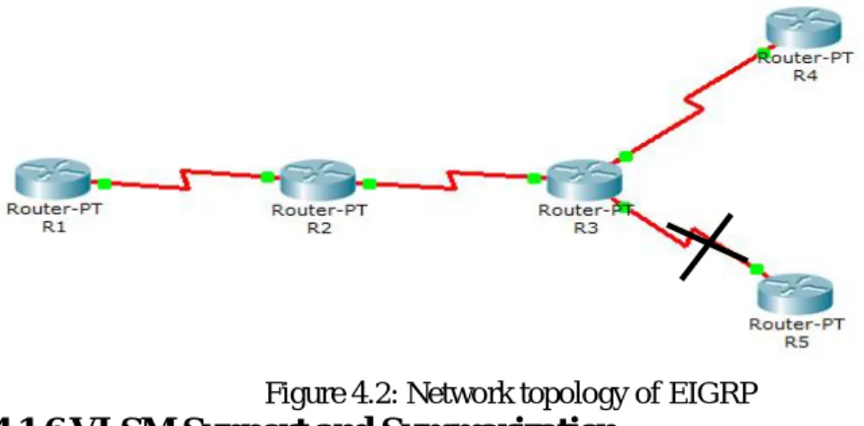
Enhanced Interior Gateway Routing Protocol (EIGRP) is a CISCO proprietary protocol, which is an improved version of the interior gateway routing protocol (IGRP). EIGRP is being used as a more scalable protocol in both medium and large scale networks since 1992. EIGRP is said to be an extensively used IGRP where route computation is done through Diffusion Update Algorithm (DUAL). However, EIGRP can also be considered as hybrid protocol because of having link state protocol properties. A network topology of EIGRP is obtainable figure-4.2 in the following diagram [8].
©Daffodil International University 18
Figure 4.2: Network topology of EIGRP
4.1.6 VLSM Support and Summarization
As one of the more sophisticated classless routing protocols, EIGRP supports the use of Variable Length Subnet Masks. This is really important because it allows for the conservation of address space through the use of subnet masks that more closely fit the host requirements, such as using 30-bit subnet masks for point-to-point networks.
And because the subnet mask is propagated with every route update, EIGRP also supports the use of discontinuous subnets figure-4.3, something that gives us a lot more flexibility when designing the network’s IP address plan.
Figure 4.3 a discontinuous network Advantages of EIGRP are listed below:
There are some advantages provides by EIGRP as follows:
Easy to configure.
Loop free routes are offered.
It keeps a backup path in the network to get the destination.
Multiple network layer protocols are included.
©Daffodil International University 19
EIGRP convergence time is low and it is responsible for the reduction of the bandwidth utilization.
It can work with Variable Length Subnet Mask (VLSM) and Class Less Inter Domain Routing (CIDR).
EIGRP also supports the routing update authentication.
Disadvantages of EIGRP are following bellow:
Considered as Cisco proprietary routing protocol.
Routers from other vendors are not able to utilize EIGRP.
©Daffodil International University 19
Chapter 5
Configure Basic IP Phone & Dial Peers
5.1 Configure Cisco IP Phone 7960 & Dial Peers
Cisco IP phones have buttons that you can program to dial a number when they are pressed. For example, the default template for the Cisco 7960 IP phone has four speed dial buttons. These buttons can be configured by a user that has been associated with an IP phone or by the Call Manager server administrator.
However, dial peer represent the call setup process through a packet network that uses Cisco IOS® software voice-enabled gateways/routers.
5.1.1 Application (telephony-service)
To select a session-level application for all extensions (ephone-dns) in a Cisco Unified CME, use the application command in telephony-service configuration mode.
To disable use of an application for all extensions, use the no form of this command [10].
application application-name no application
Table 5.1: Syntax Description of Application (telephony-service)
5.1.2 Auto Assign
To automatically assign an already defined telephone or extension number to button 1 of Cisco Unified IP phones as they register for service with a Cisco Unified CME router, use the auto assign command in telephony-service configuration mode. To return to the default of not automatically assigning dn-tags, use the no form of this command [2].
©Daffodil International University 20
Table: 5.2 Syntax Description of Auto Assign
5.1.3 Ephone
To enter Ethernet phone (ephone) configuration mode for an IP phone for the purposes of creating & configuring an ephone, use the ephone command in global configuration mode. To disable the ephone & remove the IP phone configuration, use the no form of this command.
Table: 5.3 Syntax Description of Ephone Tag
5.1.4 Ephone-dn
To enter ephone-dn configuration mode to configure a directory number for an IP phone line, intercom line, paging line, voice-mail port, or message-waiting indicator (MWI), use the ephone-dn command in global configuration mode. To delete an ephone-dn, use the no form of this command [2].
Table: 5.4 Syntax Description of Ephone-dn Tag
©Daffodil International University 21
5.2 Understanding Dial Peers
This topic describes dial peers and their applications.
A dial peer is an addressable call endpoint.
Dial peers establish logical connections, called call legs, to complete an end- to-end call.
Cisco voice-enabled routers support two types of dial peers:
-POTS dial peers: Connect to a traditional telephony network -VoIP dial peers: Connect over a packet network
5.2.1 Configuring POTS Dial Peers
Follow these steps to configure POTS dial peers:
Table: 5.5 Step For POTS Dial Peers Step Action
1. Configure a POTS dial peer at each router or gateway where edge telephony devices connect to the network.
2. Use the destination-pattern command in the dial peer to configure the telephone number.
3. Use the port command to specify the physical voice port that the POTS telephone is connected to.
5.2.2 Configuring VoIP Dial Peers
Table: 5.6 Step For VOIP Dial Peers Step Action
1. Configure the path across the network for voice data.
2. Specify the dial peer as a VoIP dial peer.
©Daffodil International University 22
3. Use the destination-pattern command to configure a range of numbers reachable by the remote router or gateway.
4. Use the session target command to specify an IP address of the terminating router or gateway.
5. Use the remote device loopback address as the IP address.
5.2.3 Configuring Destination-Pattern Options
The destination pattern associates a telephone number with a given dial peer. The destination pattern also determines the dialed digits that the router collects and forwards to the remote telephony interface, such as a PBX, Cisco Call Manager, or the PSTN. You must configure a destination pattern for each POTS and VoIP dial peer that you define on the router.
The destination pattern can indicate a complete telephone number, a partial telephone number with wildcard digits, or it can point to a range of numbers defined in a variety of ways. Destination-pattern options include the following:
5.2.4 Default Dial Peer
When a matching inbound dial peer is not found, the router resorts to the default dial peer.
Note Default dial peers are used for inbound matches only. They are not used to match outbound calls that do not have a dial peer configured. The default dial peer is referred to as dial peer 0.
5.2.5 Matching Inbound Dial Peers Peer 0
When determining how inbound dial peers are matched on a router, it is important to note whether the inbound call leg is matched to a POTS or VoIP dial peer. Matching occurs in the following manner:
Inbound POTS dial peers are associated with the incoming POTS call legs of the originating router or gateway.
©Daffodil International University 23
Inbound VoIP dial peers are associated with the incoming VoIP call legs of the terminating router or gateway.
Three information elements sent in the call setup message are matched against four configurable dial-peer command attributes [2].
5.2.6 Matching Outbound Dial Peers
Outbound dial-peer matching is completed on a digit-by-digit basis. Therefore, the router or gateway checks for dial-peer matches after receiving each digit and then routes the call when a full match is made. The router or gateway matches outbound dial peers in the following order:
How the Router or Gateway Matches Outbound Dial Peers Table: 5.7 Step For outbound Dial Peers
Step Action
1. The router or gateway uses the dial peer destination-pattern command to determine how to route the call.
2. The destination-pattern command routes the call in the following manner:
On POTS dial peers, the port command forwards the call.
On VoIP dial peers, the session target command forwards the call.
3. Use the show dial plan number string command to determine which dial peer is matched to a specific dialed string. This command displays all matching dial peers in the order that they are used.
©Daffodil International University 24
Chapter 6
Configurations & Verifications 6.1 Router Configuration
This section discusses the configuration of Router, efficient routing EIGRP and Telnet using Packet Tracer on this network Infrastructure. There are configured so many things such as hostname, console login, remote login, password setup, banner, set up necessary IP on specific interface or sub interface as well as create DHCP pool. Also there are configured telephony services for Cisco IP communicator. These configurations are applicable for all three routers individually.
6.2 Switch Configuration
This section discusses the configuration of Switch and VLAN using Packet Tracer.
VLANs logically segment switched networks based on an organization's functions, project teams, or applications as opposed to a physical or geographical basis. There has been configured VLAN based on the infrastructure. Also there are configured some other things such as hostname, console login, remote login, password setup, banner, set up necessary IP on specific interface as well as VTP [7].
6.3 DHCP Server
DHCP works by providing a process for a server to allocate the IP information to clients.
Clients lease the information from the server for an administratively defined period [9].
6.3.1 Major DHCP Features
• Automatic allocation – DHCP assigns a permanent IP address to a client.
• Manual allocation – The IP address for the client is assigned by the administrator. DHCP conveys the address to the client.
• Dynamic allocation – DHCP assigns, or leases, an IP address to the client for a limited period of time [9].
©Daffodil International University 25
6.3.2 Configuring DHCP
Table: 6.1 Syntax for DHCP Configuration
6.3.3 DHCP Operation
Figure: 6.1 DHCP Operation
©Daffodil International University 26
6.4 Verification, Dial-Up & Testing
Verify communication between various hosts in the network. Document the results of the tests using Packet Tracer in the table.
Table 6.2: Verify, Communication & Dial-up between various hosts in the network.
Source Destination Protocol/Dial Expected Result
Data Verified
Voice Verified Host on
Admin
Host on HR
Ping(ICMP) Success Operational Operational Host on
Admin
Host on HR
Dial-Up Connect Operational Operational Host on
IT
Host on Admin
Ping(ICMP) Success Operational Operational Host on
IT
Host on Admin
Dial-Up Connect Operational Operational Host on
Accounts
Host on Audit
Ping(ICMP) Success Operational Operational Host on
Accounts
Host on Audit
Dial-Up Connect Operational Operational Host on
Managem ent
Host on IT Ping(ICMP) Success Operational Operational
Host on Managem
ent
Host on IT Dial-Up Connect Operational Operational
©Daffodil International University 27
Chapter 7 Conclusion 7.1 Conclusion
This network is IP based network model. An IP based network infrastructure model has been developed for a renewed private organization in Bangladesh. Proposed network design in scalable, secured, effective and fault tolerable. It is an area based network model. Here LAN and WAN technologies are used including voice & data.
Here collision free, full duplex Ethernet LANs model implemented for 100Mbps data transmission.
7.2 Limitations
It has been considered as Cisco proprietary routing protocol. Because routers from other vendors are not able to utilize EIGRP.
7.1 Future Work
This network can be expanded in future as required. Some wireless connectivity can be introduced near future. Also it can be included some other vlan for voice & data both.
©Daffodil International University 28
References
[1] Todd Lammle, Cisco Certified Network Associate, Copyright © 2007 by Wiley Publishing Study Guide, Sixth Edition, Page No. 119-121, 329,341,363,374,377, April-2015.
[2] Learn about configuration, available at << http://www.cisco.com/>>, last accessed on 07-04- 2015 at 10:00am.
[3] Taken static vs dynamic routing idea from << http://www.wikipedia.org/>>, last accessed on 07-04- 2015 at 11:00am.
[4] Learn about technical design & configuration, available at <<http://www.youtube.com/>>, last accessed on 07-04-2015 at 12:00pm.
[5] Taken troubleshooting idea from << http://www.9tut.com/>>, last accessed on 08-04-2015 at 10:00pm.
[6] Taken ip phone setup idea from << http://www.ehow.com/>>, last accessed on 08-04-2015 at 11:00pm.
[7] Taken vlan concept from << http://www.netacad.com/>>, last accessed on 08-04-2015 at 10:00am.
[8] Gathered routing protocol idea from << http://www.freeccnastudyguide.com/>>, last accessed on 10-04-2015 at 11:00pm.
[9] Learn about DHCP service available at << http://www.ciscopress.com/>>, last accessed on 09-04- 2015 at 11:00pm.
[10] Taken telephony service clue from << http://www.opennet.ru/>>, last accessed on 09-04-2015 at 11:00pm.
[11] Taken soft phone hints from << http://www.3cx.com/>> last accessed on 10-04-2015 at 10:00am.
[12] Occupied packet tracer update from << http://www.packettracernetwork.com/>> last accessed on 10-04-2015 at 11:00am.
[13] Learn about soft phone from<< http://www.ipphonex.com/>>, last accessed on 09-04-2015 at 10:00pm.
[14] Got how to assign voice & data vlan from CCNA Exploration 4.0, last accessed on 11-04-2015 at 11:00pm.
[15] Taken VTP idea from <<http://www.learningnetworking.cisco.com/>> last accessed on 11-04- 2015 at 11:00am