TABLE OF CONTENTS
KEYNOTE SPEAKERS
Earthquake Risk Mitigation: A Story of Local Solutions
Sudhir K. JainSeismic Design Enforcement Process of High-Rise Buildings in Jakarta
Gde Widiadnyana Merati, Davy Sukamta, I Wayan SengaraRecent Updates to the MCE
RGround Motion Maps in US Building Codes
Nicolas Luco
Seismic Protective Systems for Super-Tall Buildings and Their Contents
Kazuhiko KasaiDefining Cost-Effective Strategies for Safety Upgrading of School Buildings at
Regional Scale in Seismic Prone Areas
Stefano Grimaz
Development on Risk-Based Seismic Design Criteria and Ground Motions for
High-Rise Buildings in Jakarta
I Wayan Sengara, M. Addifa Yulman, Putu Sumiartha, Andri Mulia
Performance Based Design for Tall RC Building with Outrigger & Belt-Truss Under
Seismic Loading
Bambang Budiono, M. A. Jonathan
Numerical Simulation of Shallow Water Waves with Bottom Boundary Layer
Development
Hitoshi Tanaka, Mohammad Bagus Adityawan, Yuta Mitobe
Post-Tensioned Timber Buildings In New Zealand: Research, Design and
Implementation into Real Case Studies
Alessandro Palermo
Loss Optimization Seismic Design
Rajesh P. Dhakal, Sandip K. SahaSeismic Earth Pressures on Deep Stiff Walls
N. Sitar, N. WagnerWRG: A Practical and Efficient Innovative Solution for Seismic Resistant Concrete
Structures
SPECIAL PRESENTATIONS
SPECIAL SESSIONS
TECHNICAL PAPERS
Disaster Risk Reduction in Indonesia: Progress and Challenges
Krishna S PribadiProgress Report on The Development of Seismic Hazard Maps of Indonesia 2016
Masyhur Irsyam, Danny Hilman Natawijaya,, Sri Widiyantoro, Irwan Meilano, WahyuTriyoso, Ariska Rudiyanto, Sri Hidayati, M. Asrurifak, Arif Sabaruddin, Lutfi Faisa
Current Status of Indonesia Accelerograph Network
Murjaya, Masturyono, SupriyantoMengkampanyekan Sekolah Aman Melalui Retrofitting
Isria Sirubaya, Maulinna UtaminingsihSekolah Siaga Bencana
Wahyu NovyanSchool Safety
Malashree Bhargava, Adrianus Tanjung, Victor Igbokwe, Utkarsh Pandey
1.
3
rdICEEDM-01
Identification of Potential Criteria and Assessment of Escape
Building in Banda Aceh
Hafnidar A. Rani, Meillyta
3
rdICEEDM-02
Risk Management Model Housing Reconstruction Basing The
Community in The Aftermath of The Earthquake
Wendi Boy, Suripin, M. Agung Wibowo
3
rdICEEDM-03
Development of Earthquake Risk Assessment Model for Roads in
Indonesia
Mona Foralisa Toyfur, Krishna S. Pribadi, Sony S. Wibowo, I Wayan Sengara
3
rdICEEDM-04
How Community Perception Influence The Earthquake Risk
Analysis in Bandung Barat District?
Aria Mariany, Teti Armiati Argo, Roos Akbar, Djoko Abi Suroso, Irwan Meilano, Krishna S. Pribadi
3
rdICEEDM-05
Business Continuity Management System for The Risk
Governance in Port Sub-Sector
Kenji Ono, Kentaro Kumagai, Yasuhiro Akakura, Felipe Caselli
3
rdICEEDM-06
The Role of Construction Industry in Post Disaster Recovery
–
Comparative Study Between Indonesia and Japan
–
Masamitsu Onishi, Krishna S. Pribadi3
rdICEEDM-07
StIRRRD: A Disaster Risk Reduction Program in Indonesia
Phill Glassey, Iman Satyarno3
rdICEEDM-08
Advanced Design of Sand Compaction Pile as The Liquefaction
Mitigation
Mitsuo Nozu, Naotoshi Shinkawa, Tooru Inoue
3
rdICEEDM-09
The Estimated Spatial Ground Acceleration of The 2006
Yogyakarta Earthquake Composed from The Field Survey
Widodo Pawirodikromo3
rdICEEDM-10
Seismic Deformation of Narrow Reinforced Earth Embankment
Walls
Fransiscus S. Hardianto, Kim M. Truong
3
rdICEEDM-11
Modelling of Site Specific Response Spectrum for Building in
Makassar
Ardy Arsyad, Ryan Rante, Abdul Muthalib
3
rdICEEDM-12
Development of Time Series for Soft Clay Site in North Jakarta,
Indonesia
Sindhu Rudianto, Ramin Golesorkhi
3
rdICEEDM-13
Seismic Design Review of Underground Structure for The Case
of Jakarta MRT
Irawan Tani, Yudha Adi, Riky Budiman
3
rdICEEDM-14
Isovolcanic Map Application for Identifying Attenuation of
Damage Intensity in 2010 Merapi Eruption
Meassa Monikha Sari
3
rdICEEDM-15
Peak Ground Velocity Prediction Equation for
Andaman-Nicobar Region
Prabhu Muthuganeisan, S.T.G. Raghukanth
3
rdICEEDM-16
Comparative Study Wald Allen’s and Matsuoka’s Method for
Mapping Earthquake Jakarta
Rahmawati, H. A., Prakoso, W. A, Rudyanto. A
3
rdICEEDM-17
Land Reclamation Developments in Seismic Areas: The Selection
of The Geotechnical Earthquake Engineering Approach and An
Integrated Approach Make The Difference
Steenbakkers, A.J.M., Nilasari, P., Adrichem, J.D
3
rdICEEDM-18
The Comparison of Measured and Estimated Shear-Wave
Velocity (Vs30) for Yogyakarta Area
Astri Rahayu, Widjojo A. Prakoso, Imam A. Sadisun, M. Muzli, Ariska Rudyanto, Agus S. Muntohar
3
rdICEEDM-19
Numerical Simulation of Dynamic Compaction to Evaluate
Liquefaction Potential at Northern Jakarta Coast Reclamation
Pebri Herry, I Wayan Sengara, Marcello Djunaidy3
rdICEEDM-20
Dynamic Shear Behavior of Lining-Soil Interface
Changwon Kwak, Innjoon Park, Dongin Jang3
rdICEEDM-21
Geology, Geomorphology and Failure Mechanism of Volcanic
Landslide: A Case Study from Large Landslide in Banjarnegara,
Indonesia
I Putu Krishna Wijaya, Christian Zangerl, Wolfgang Straka, Franz Ottner, Yukni Arifianti
3
rdICEEDM-22
Numerical Modeling of Solitary Wave Propagation
Bagus Pramono Yakti, Akbar Rizaldi, Mohammad Farid, Febya Nurnadiati, Mohammad Bagus Adityawan
3
rdICEEDM-23
A Review on Mechanism of Landslides Induced by Earthquake
in Sumatra
Yukni Arifianti, Kristianto, Pamela, Sumaryono, Akhmad Solikhin
3
rdICEEDM-24
Ground Motion Simulation for Tsunami-Genic Earthquake in
Sunda Arc Region
Dhanya, J., Raghukanth S.T.G.
3
rdICEEDM-25
Aging Effects on One Way Cyclic Loading Resistance of Loose
Silty Sand
3
rdICEEDM-26
Evaluation of the Damage of Buildings and Infrastructures Based
on Liquefaction Potential Index (LPI) at 30 September 2009
Padang Pariaman (West Sumatra) Earthquake
Paulus P. Rahardjo
3
rdICEEDM-27
Application of Microseismic Monitoring in Underground Block
Cave Mine
Arjuna Ginting, Erwin Riyanto, Achmad Muttaqi, Setyo Akhasyah, Fachry Salim, Septian Prahastudhi, Farid Gumilang, Turgod Nainggolan, Eric Sitorus
3
rdICEEDM-28
Site Specific Response Analysis of Liquefiable Sand Deposit
I Wayan Sengara, Fritz Nababan, Putu Sumiarta, Andri Mulia
3
rdICEEDM-30 Stability of Gunung Tigo Slope: Pore-Pressure Effects Analysis
Abdul Hakam, Febrin Anas Ismail, Nanda
3
rdICEEDM-31
An Overview of Design Response Spectra in The Indonesian
Seismic Code SNI 1726:2012
Suradjin Sutjipto
3
rdICEEDM-32
Retrofitting of Non-Engineered Constructions in Developing
Countries
Teddy Boen, Hiroshi Imai
3
rdICEEDM-33
Pushover Analysis of Hybrid Steel and Reinforced Concrete
Moment Resisting Frames System on The Building Vertical
Extention
Andy Prabowo
3
rdICEEDM-34
Seismic Analysis of Large-Panel Buildings
Iu. Nemchynov, N. Maryenkov, A. Khavkin, K. Babik,V. Poklonskyi, O. Fesenko
3
rdICEEDM-35
Structure Analysis of The Temporary Evacuation Site (TES)
Building in Prone Areas of Tsunami (Lo
cation: The Serangan’s
Traditional Market, Denpasar, Bali)
Sutarja, I N., Suwarsa Putra, TG., Ratih Novyanti Dewi
3
rdICEEDM-36
Modeling and Analysis of The Behavior of RC Beam-Thin
Column Eccentric Joints Subjected to Seismic Loading
I Ketut Sudarsana, Ida Ayu Made Budiwati, Putu Didik Sulistiana
3
rdICEEDM-37
Structural Integrity Under Seismic Loading of Low-Medium Rise
Structures: Numerical Analysis of Steel Frames
I Gede Adi Susila, Ida Ayu Made Budiwati, N. Budiartha RM, Dewa Amertha Semadi
3
rdICEEDM-38
The Effect of Shear Wall Strengthening Against Students
Dormitory of Andalas
University (Case Study: ˪ Corner Type)
Fauzan, Febrin Anas Ismail, Zaidir, Siska Apriwelni, Ridho Aidil Fitrah, Muhammad Warsa3
rdICEEDM-40
Earthquake Response of Cable Stayed Bridge with Steel Girder
using Response Spectrum and Time History Analysis During and
After Construction with Cable Tuning Case Study Merah Putih
Bridge, Ambon, Indonesia
3
rdICEEDM-41
Numerical Modelling of Traditional Base-Isolation and
Dissipation Energy (EDU) System of Timber Frame
(Non-Engineered) Structure Under Seismic Loading
I Gede Adi Susila, Ketut Sudarsana
3
rdICEEDM-42
Development and Updating of Standard on Seismic Load Design
for Conventional Bridges in Indonesia
Fahmi Aldiamara, Desyantia, Herry Vaza
3
rdICEEDM-43
Finite Element Analysis of Perforated - Reinforced Elastomeric
Isolators (PREIs) Under Pure Lateral Loading
Yudha Lesmana, Tavio, Hidayat Soegihardjo
3
rdICEEDM-44
Recent Developments on Seismic Performance of Steel Plate
Shear Walls
Ronny Purba, Michel Bruneau
3
rdICEEDM-45
Stability Design for Steel Structures and The Implication Due to
Wind and Seismic Loads
Alexander Vega Vásquez, Gerardo Chacón Rojas
3
rdICEEDM-46
Sliding Isolation Pendulum as The Seismic Mitigation Strategy,
Study Case: Holtekam Steel Arch Bridge
Tri Suryadi, Demson Sihaloho, Zdenek Fukar
3
rdICEEDM-47
Behaviour of Basement Wall Subjected to Synthetic Harmonic
Ground Motions
Ahmad Beltian Winner, Widjojo A. Prakoso
3
rdICEEDM-48
Case Study of Slender RC Shear Wall Using Displacement Based
Design
Tanri Wijaya3
rdICEEDM-49
Proposed Improvement to The Current Design and Method of
Concreting RC Column for Earthquake Resistant Buildings
Hadi R. Tanuwidjaja, Euricky E. Tanuwidjaja, Grace K. Santoso3
rdICEEDM-50
Quick Assessment of High-Rise Building Seismic Vulnerability
Based on Column Dimensions and Material Properties
Mulyo Harris Pradono
3
rdICEEDM-51
Cyclic Tests and Strength Analysis for Reinforced Concrete
Coupling Beams with Span-to-Depth Ratio Equals 1.0
Erwin Lim, Shyh-Jiann Hwang, Ting-Wei Wang
3
rdICEEDM-52
Experimental Study of Confined Mansory Wall With Opening
Under Cyclic Load
Dyah Kusumastuti, Made Suarjana, Ferdy Whisnu Prasetyo, Rildova
3
rdICEEDM-53
Probabilistic Formulations for Earthquake Resistant Structural
Design
Adang Surahman
3
rdICEEDM-54
Development of Numerical Model for Pushover Analysis of
Confined Masonry With and Without Opening
Made Suarjana, Dyah Kusumastuti, C. A. Riva'i, N. I. Pratiwi
3
rdICEEDM-55
Seismic Behavior of Base-Isolated Residential House with
Various Soil Type in High Seismic Regions by Nonlinear
Time-History Analysis
Tavio, Hidajat Sugihardjo, Yudha Lesmana
3
rdICEEDM-56
Tsunami Shelter in Padang by Utilization of The Advantage of
Composite Structure Material Made of H-Section Steel and
Reinforced Concrete
Fauzan, Febrin A. Ismail, Shafira R. Hape, Abdul Hakam
3
rdICEEDM-57 Liquefaction Potential Analysis Using SPT and CPT Data (Case
Study : Benoa Area, Denpasar)
The 3
rdInternational Conference on Earthquake Engineering and Disaster Mitigation 2016 (ICEEDM-III 2016)
Stability of Gunung Tigo Slope:
Pore-Pressure Effects Analysis
Abdul Hakam
a*, Febrin Anas Ismail and Nanda
aWest Sumatra AARGI, Civil Engineering of Andalas University, Padang, IndonesiaAbstract
Landslide at Gunung Tigo-Cumanak in Pariaman due to the Padang earthquake in 2009 has buried three underneath villages. This earthquake induced landslide also killed hundreds people and demolished access roads. This paper elaborates the landslide back analysis with focus on the increasing excess pore-pressure. Field survey has been conducted as well as tests of soil properties on the location to get the slope geometric and soil mechanics data. Based on results of the field survey and soil test, the slope stability analyses then are performed. The special aim of this simulation is to elaborate the effect of pore-pressure on slope stability. The landslide analyses were done by considering the static and dynamic loads. The dynamic analyses are considering the earthquake load of Padang in 2009. The results of this study presented in the terms of pore-pressure and safety factor relationship for both static and dynamic loads. This study is very useful to understand the effect increased pore-pressure induced by an earthquake on slope stability.
Keywords: earthquake; landslide; dynamic analysis; mitigation.
1. INTRODUCTION
Earthquakes in some places can trigger landslides such have been reported [1] and [2]. The earthquake triggered landslides can be generally caused by the additional inertia forces or the increased pore water pressure in the slope soil mass. Both of them result the decreasing slope stability in terms of factor of safety.
Strong earthquakes often result in liquefaction. Liquefaction is a phenomenon the change of the soil from the solid state into a liquid state. This phenomenon caused by the increase in soil pore water pressure that exceeds the contact stress in the soil, so that the effective stress in the soil theoretically becomes zero. Effective stress is the difference between the total stress and the pore water pressure that can be written as follows:
' =- u (1)
Where:
' = effective stress
*Corresponding author. Tel.: +61-812-67-38759; Fax.: +61-751-72566.
= total stress, and u = pore water pressure
Based on the experiences of liquefaction testing conducted by the authors [3] as well as other researchers [4], there are not all seismic motions can result liquefaction. Liquefaction is influenced by some physical and mechanical factors of soil. The most factors that effect the liquefaction are the strength of the seismic motion which is represented by acceleration, a and mean soil particle size, D50. However, the increase in pore water pressure more than 70% can be considered to cause liquefaction [4].
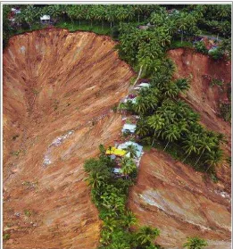
During Padang earthquake in 2009, there has been reported a huge landslide in Gunung Tigo - Pariaman. The landslide had buried three villages below, killed hundreds of people and destroyed access roads (Figure 1) [5]. Based on field observations following the earthquake in Padang, 2009, in The Gunung Tigo has found flow of water at several point where have experienced catastrophic landslide. This evidence indicates that the landslide on the slope of Gunung Tigo was also caused by an increase in pore water. In this paper, the location of Gunung Tigo landslide is taken as a case study to demonstrate the effect of pore water pressure during the earthquake to slope stability.
Fig. 1. Gunung Tigo landslide
2. SLOPE STABILITY ANALYSIS
In the soil mechanics field, the shear soil strength can be expressed in terms of effective stress and cohesion in the soil which is written as follows:
= tan( ) + c (2)
Where: = shear stress
= normal stress
Increase in pore water pressure can reduce the effective strength of the soil, such that the shear strength is also reduced. In general for the slopes in static condition, the stability is expressed as the ratio between the shear resistance of soil at failure plane to the diving shear stress which is an accumulation of forces that act on the landslides (Fig. 2). The ratio of the resistance and the driving stresses is known as a safety factor that is written as follows:
SF = /m (3)
Where:
SF = safety factor
= shear resistance, and
m = driving stress that caused the landslide
Fig.2. Landslide mechanism
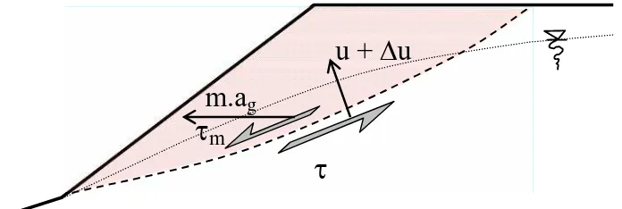
For the special case where the slopes have sufficient saturated soil with certain ground water level and experiencing the earthquake such that the pore water pressure is increased, the amount of forces will effect the factor of safety (Fig. 3). Those forces will increase the driving stress and on the other hand will reduce the stress resistance of the slope. The safety factor in this condition is then written in the following general equation:
SFd =d /md (4)
Where:
SFd = dynamic safety factor,
md= dynamic pressure caused landslides =m + f(a)
d= dynamic shearing resistance =- f (u,u)
u = increase in pore water pressure due to seismic
f (a) = inertia force caused by the earthquake with acceleration a f (u,u) = forces as function of pore water pressure
mass of landslide
failure plane
mu +
u
m.a
gFig.3. Dynamic landslide mechanism
3.
ANALYSIS AND RESULTS
Field investigation on the location of the Gunung Tigo landslide in year 2009 has been done. This field study is intended to gain the geometry of the slope along with soil data for slope stability analysis. The test results of soil samples in laboratory are shown in Table 1. That parameter values the are used in the calculation of slope stability analysis.
Table 1. Tsunami induced forces
Based on observations in the field, the slopes of Gunung Tigo has an average slope of 40 degrees. Failure plane of the slope located at a depth of 1m to 2m from the slope surface. Saturated soil at failure plane field has a thickness of about 50 cm. Based on these data then a series of slope stability analysis are performed with taking into account the increase in pore water pressure. The calculation results are showed in Fig. 4 and 5 below. In normal condition, the static safety factor of the slope SF is 1.9 and at the earthquake load the safety factor, SFd is 1.2
Based on Fig. 4 which shows the relationship between the increase pore water pressure and stresses in the soil, it can be seen that the effective stress will be decreased in such a way to zero at when the increase in pore water reaches about twice of the initial one. Theoretically at this time the soil on the grained soil type of slope will suffer from liquefaction.
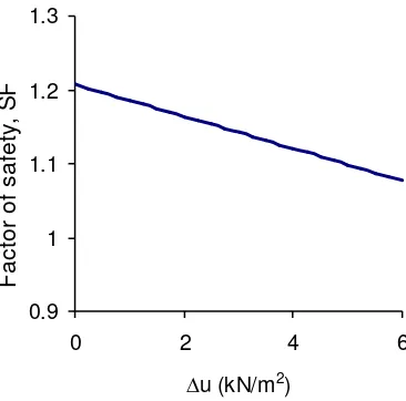
Fig. 5 shows the increase pore water pressure respect to the slope safety factor. Slope safety factor decreases with the increasing pore water pressure. Slope safety factor value is in a critical condition that is close to 1.0 when the pore water pressure has reached almost twice the initial conditions. In fact, the slope of Gunung Tigo has collapsed, it is theoretically possible since non-homogeneous soil in many spots. At that spots the cohesion that is less than the results of this test, will cause the slope failure. The failure at one point will trigger the adjacent point at the slope. It continues such that the overall slope of Gunung Tigo were collapse.
Parameter Value Unit
Fig. 4. The increased pore water pressure versus stress in soil mass
Fig. 5. The increased pore water pressure versus factor of safety
CONCLUSIONS
The increase in pore water pressure in saturated soil mass can be caused by an earthquake. Although the liquefaction condition is not reached, but the increase in pore water pressure may affect the stability of the slope. In this paper has shown the increased pore water pressure to influence on the reducing the value of slope factor of safety with the example in slope failure at Guning Tigo - Pariaman. It has shown as well that the soil parameters were very significant in contributing to the factor of safety of slope is cohesion on the soil.
-2 0 2 4 6 8 10 12
0 2 4 6
∆u (kN/m2)
p
re
ss.
(
kN
/m
2 )
utot
s''
0.9 1 1.1 1.2 1.3
0 2 4 6
∆u (kN/m2)
F
a
ct
o
r
o
f
sa
fe
ty,
S
REFERENCES
[1] Bommer, J.J and Rodrıguez, C.E, "Earthquake-induced landslides in Central America", Engineering Geology 63 (2002) 189–220, 2002
[2] Chen X.L., Zhou B.G., Zhou Q. and Ran H.L., "Improvement of Methods for Earthquake-induced Landslides Assessment", 15 WCEE proceeeding, Lisbon, 2012
[3] Istijono, B and Hakam, A, "New Method for Liquefaction Assessment Based on Soil Gradation and Relative Density", International Journal on Advance Research in Science and Engineering, Vol No. 4, special issue (01), August 2015
[4] Ishihara, K, Personal communication in Slope 2015, Bali Indonesia, 2015.
The 3
rdInternational Conference on Earthquake Engineering and Disaster Mitigation 2016 (ICEEDM-III 2016)
Tsunami Shelter In Padang By Utilization of The Advantage
of Composite Structure Material Made of H-section Steel and
Reinforced Concrete
Fauzan
a, Febrin A Ismail
a, Shafira R Hape
a, Abdul Hakam
aaWest Sumatra AARGI, Civil Engineering of Andalas University
Abstract
Since Padang City is defined to have the most tsunami risk in Indonesia, there are many studies have been done to mitigate the tsunami disaster. One of the mitigation action for tsunamis is done by constructing tsunami shelters. The tsunami shelter structure must be designed to withstand during a big earthquake which occurred at first before the tsunami. Further, the structure should be able to restrain the tsunami attack along with the tsunami induced forces. Reinforced concrete is a material that has been widely used to build the existing shelter. This study describes the use of the composite material consist of H-section steel and reinforced concrete for the main structure of the tsunami shelter in Padang. Three-dimensional finite element method is used as the numerical tool to calculate the internal forces in the structure of the shelter. Based on the results of this study, it can be elaborated the advantages of the composite materials compared to the reinforced concrete for earthquake and tsunami resistant structures. One of those advantages is the relatively slim structure which resulting relatively smaller internal forces. The composite structure also requires relatively more economic foundation system compared to the reinforced concrete structure.
Keywords:earthquake, tsunami, composite, shelter, mitigation.
1.
INTRODUCTION
Based on tsunami experiences in the past, the tsunami hazard can be categorized into two terms that are short- distance (local) and long-distance tsunamis. As the general tsunamis that occurred in Indonesia, the tsunami threat in the city of Padang is coming in term of local tsunami. The tsunami sources where is very likely attach Padang city are located at subduction of the Eurosia plate and the Australian plate on the west side of the Sumatra island. From this locations, the estimated arrival time of a local tsunami is about 30 minutes following the triggering earthquake. The long-distance tsunamis that occurred 1 to 8 hours after the earthquake which are not felt by Padang people, are having a little possibility to damage Padang city.
3-6m. For the purposes of building a temporary evacuation planning was taken by 5m. This altitude is very dangerous and can be devastated buildings in the city and claimed hundreds of thousands of residents of the city of Padang.
Second, tsunami arrival time after the earthquake. For the city of Padang the predicted tsunami arrival time is 30 minutes. The earthquake locus is around the Mentawai islands. This time is enough to evacuate people from the Padang shore area to the distant area as far as 2 to 3 km. However, for the area in where there is no designed evacuation access, this time may be a limit to determine the vertical evacuation to the tsunami shelter.
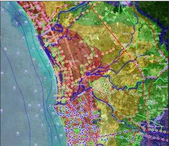
Padang has created a tsunami hazard map in which divides the city into three zones with different colors; red, green and yellow (see Fig. 1). The red zone is the lower area and close to the beach which highly affected by the tsunami. The green zone is the higher land and far from the beach so it is categorization as tsunami safe area. The yellow zone is the area between red and green which likely to be affected by the tsunami.
Historically, the Padang City was established by Dutch colonialism in beginning of 1900. The city is then grew without any clear planning. As the result, the residential settlement was developed rapidly in the area of the seashore near by in where it is now known as the red zone. After the Aceh tsunami in 2004 the residential development in the shore near was stopped. However the number people living in the red zone is still very large.
There are two options of mitigation measures were taken by Padang government. First is by developing horizontal evacuation accesses towards the safe zone and second is constructing vertical shelters in the red zone. For the area with the limited land to build the access, the temporary evacuation shelter is the choice. An evacuation shelter is in the term of building that should initially be able to resist the earthquake and than must withstand the tsunami attack.
Fig. 1. Tsunami hazard map of Padang city
2.
STRUCTURAL ANALYSIS FOR TSUNAMI SHELTERIn addition to the historical evidence, the research on a possibility of tsunami in the city of Padang has been carried out based on similar experiences in the movement of Bengkulu segment in 2007 [3]. The results of these studies indicated that the 2007 tsunami which reached the height up to 3.6m in Bengkulu might reached 1.6m in Padang. However, since there is a dike along the Padang beach with the hight of 2m, the tsunami impact was not felt. However for tsunami height more than 5m, the severe damage may occur in the Padang city. Therefore the appropriate evacuation will greatly help the avoid or reduce tsunami victims.
The study of the tsunami safe structure in Thailand has been done as a result of the Aceh tsunami in 2004, which reached the country [4]. Based on the possibility of tsunami attack on the building structure, then the structural analysis the shelter structure divided into two different criteria; First the shelter in the area where large debris is highly suspected and the shelter in the area where large debris is impossible. Furthermore, based on those criteria the guidance of tsunami safe structural analysis was proposed. The tsunami safe structures are required to have tolerance for minor damage. The structure which is not expected to be attacked by debris must have a good connection between the inside and outside elements. While the structure is estimated to be attacked by debris, must be planned with special damping connection between the outside and inside elements of the building.
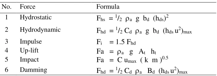
For the purposes of tsunami shelter, it has been a guidance for the tsunami induced loads that work on the structures [5]. Meanwhile the guidance regarding the room function and additional facilities are stated in the additional code [6]. The tsunami induced forces in that code are adopted in this study. In this study, the shelter structure is made of steel-concrete composite as described in the following sections. The tsunami induced forces on the structure are hydrostatic, hydrodynamic, impulse, floating (up-lift), impact and damming of debris. Each load formula is written in Table 1 and illustrated in Fig. 2 (a) to (f).
Table 1. Tsunami induced forces
No. Force Formula
1 Hydrostatic
F
hs=
1/
2
ag b
d(h
ds)
22 Hydrodynamic
F
hd=
1/
2C
d
ag b
d(h
dsu
2)
max3 Impulse
F
i= 1.5 F
hd4 Up-lift
Fa =
ag A
th
t5 Impact
Fa = C u
max( k m )
0.56 Damming
F
hd=
1/
2
C
d
aB
d(h
dsu
2)
maxWhere
a = sediment-salty water density (1100 kg/m3) g = gravity acceleration (9.81 m/dt2)
bd = wall width hds = tsunami hight
Cd = drag constant (2.0 is suggested ) u = water velocity
At = floor area
ht = the hight of trapped air
C = mass constant (2.0 is suggested) umax = debris velocity
k = stiffness of the debris m = mass of the debris h = dam hight
(a) Hydrostatic (b) Hydrodynamic
(c) Impulse (d) Up-lift
(e) Impact (f) Damming
Fig. 2. Illustration of tsunami induced forces
The forces are then applied to the structural elements that to withstand the loads of tsunami to get the internal forces of the structure. The structural analysis of internal forces is done using numeric tool based on finite element method.
3.
ANALYSIS AND RESULTSFig. 3. The finite element of the shelter structure
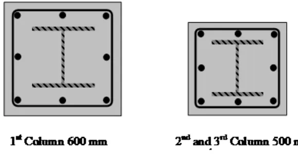
Further, analysis of the internal forces in the structure elements of the building is done by combining dead loads, live loads and seismic loads to get the maximum forces. Based on those internal forces, the steel and concrete composite structure is estimate to obtained the appropriate profiles. The maximum combination forces in this analysis stage are; 1st column has the axial force of P = 808 kN, moment of M = 241 kNm and shear force of N = 95 kN for first column. The calculation result obtained the composite dimensions H -300.300.10.15 for column of 3rd and 2nd floor and it is H-350.350.12.19 for the 1st floor columns as shown in Fig. 4. This dimensions are then used for the structural analysis under the tsunami loads.
Fig. 4. The column cross sections
To gain an effective structure, the walls of the 1st and 2nd floors of the building is designed in such a way collapse in case of tsunami. This concept have an advantage to obtain smaller tsunami forces on the structure. Then, based on the analysis of the structure due to the tsunami induced forces it is obtained the maximum combination of the axial force P = 300 kN and moments M = 460 kNm and normal force N = 361 kN. Those internal forces are then combined with other internal forces that works in the structure according to the following rules (FEMA, 2012):
Load Combination : 1.2 D + 1.0 Ts + 1.0 Lr + 0.25 L (1)
where D is the dead load, Ts is the maximum tsunami load, Lr is the refuge load, and L is the other live load.
Compared to the use of conventional reinforced concrete structure, the dimensions of reinforce concrete structure will be larger. This is initially due to the thickness of the floor plate to meet the standard regulations. For the example, thickness of concrete on the floor plate is 10cm for composite, while for conventional reinforced the minimum required thickness is 12cm. The reinforced concrete plate has increased the floor mass of at least 20%. This in turn in the need of additional dimension to the other supporting elements, such as beams and columns as well as the foundation. Finally, the increasing size of the beams and columns will also increase in the forces caused by the tsunami.
CONCLUSIONS
Padang city historically has experienced several tsunami. The Bengkulu earthquake in 2007, the tsunami waves have reached the Padang city with the maximum height of less than 2m. In the future there most likely will be tsunami waves attack and devastate the Padang city with the height up to 5m. So it is necessary to prepare a mitigation actions to evacuate people by both horizontally and vertically ways.
In this study has successfully been designed a tsunami shelter in the form of a 3-storey building. The shelter building is made of concrete-steel composite material. Initially, the building is planned to be resistant to combined forces of static and earthquake loads. Furthermore, the loads of tsunami induced on the building are combined with other internal forces.
The composite structure used for the building shelter is considered to be more efficient than ordinary reinforced concrete material. This is due to the relatively small dimensions of the structure will result in smaller forces in anyway.
REFERENCES
[1] Jose´ C. Borrero, Kerry Sieh, Mohamed Chlieh, and Costas E. Synolakis, Tsunami inundation modeling for western
Sumatra, PNAS, vol. 103 no. 52, December 26, 2006 , pp. 19673–19677
[2] Ismail, Febrin and Hakam, Abdul and Post, Joachim, Assessment of Building Vulnerability Due To Tsunami in Padang City, In: International Conference on Earthquake Engineering and Disaster Mitigation. Earthquake Disaster Risk Reduction: Engineering Challenges after Recent Disasters, 2008, Jakarta - Indonesia
[3] Aydan, F. Imamura, T. Suzuki, I. Febrin, A. Hakam, M. Mera, P.R. Devi., Report: A Reconnaissance Report on The Bengkulu Earthquake of September 12, 2007, Japan Society of Civil Engineers (JSCE) and Japan Association for Earthquake Engineering (JAEE), November 2007, Japan
[4] Pimanmas, p. Joyklad, and p. Warnitchai, Structural design guideline for tsunami evacuation shelter, Earthquake and tsunami vol. 04, no. 269, 2010
[5] FEMA P646, Guidelines for Design of Structures for Vertical Evacuation from Tsunamis 2nd ed., APPLIED
TECHNOLOGY COUNCIL, 201 Redwood Shores Pkwy, Suite 240, Redwood City, April 2012, California