QUALITY MONITORING OF LARGE STEEL BUILDINGS USING TERRESTRIAL
LIDAR TECHNIQUE
Yanmin Wanga Guoli Wanga,b*
a. School of Geometrics and Urban Information, Beijing University of Civil engineering and
Architecture, 1 Zhanlanguan Road, Xicheng District, Beijing, 100044, P.R. China
b. State Key lab for Information Engineering in Surveying Mapping and Remote Sensing Wuhan University Luoyu
Road, Wuhan, 430079, P.R. China
Commission III, WCIII/2
Key word:
Terrestrial LIDAR, Point cloud, Extraction of feature points, Construction Quality Monitoring.Abstract: Terrestrial LIDAR Technology is used for quality monitoring in construction of large-scale steel buildings to solve the problem of quick and precise inspecting for large steel structure. Point Cloud is acquired fast and of high accuracy with tie-control points that set in different blocks. Feature points are extracted from scan data and compared with its reference points designed to analyze its variation of position and size, which has active guidance meaning for engineering construction. Finally three applications are given to prove the effectiveness of the method proposed.
1. INTRUDUCTION
Modern Large-scale steel building becomes more and more popular with the development of construction and surveying technique. For examples, 2008 Beijing
Olympic Main Stadium (Bird’s Nest), National
Gymnasium and Tianjin West Station Steel-Shell Station Building etc. all of these Large steel building have their unique appearances; The steel-structure are complex and heavy; It is generally assembled on ground and installed with big crane; Thus accurate surveying and checking is necessary to make the steel structure weld and installed successfully.
Total station is used in traditional quality monitoring to observe the components of steel ports and the quality of welding is compared with observed point feature which includes observing errors (Xiangrui Guo, 2002). The fieldwork is hard and surveying features is partially
hidden. Besides, some feature points designed don’t exist
actually so it’s impossible to get the data of points. Thus
the data acquired is limited for the complex and featureless areas.
Terrestrial LIDAR could acquire precise 3D coordinates of objects within hundreds of meters all around quickly and accurately, which meet the demands for surveying of featureless areas. Integrated analysis of target could be made conveniently with the extracted features; the measured distance and accuracy also satisfy the requirement for construct survey and quality monitoring. There has been some research and application in LIDAR technique in China (Haiying Fan, 2004; Dean Luo, 2005; Yanmin Wang, 2009).O.Monserrat (2008) use least squares 3D surface matching method to estimate
deformation parameters using local surface matching, Van Gosliga et al. (2006) use a cylinder parameterization to model a tunnel, while Alba et al. (2006) follow this approach for the structural monitoring of a large dam by fitting a 3D polynomial surface to the surveyed TLS point cloud. Eleftherios TOURNAS (2008) use the control points on images captured synchronized to measure the structural deformation. Girardeau-Montaut (2005) use octree structured Terrestrial LIDAR data to make a direct cloud to cloud comparison, which can be useful for fast and quick integrated analysis.
2. FAST AND PRECISE TERRESTRIAL LIDAR
ACQUIRING TECHNIQUE
Terrestrial laser scanner measures spatial object with dense laser beam in accordance with array, acquires the spatial points by laser ranging and stepping motors accurate measurement of the angle, forms a point cloud model which is composed of discrete points of dense space. The whole technological process includes three key technologies: connection of control network, fast data acquiring and extraction of feature points.
2.1 Connection of scan sites and control network
Multi-view scans are needed to cover an object. Control survey is intended to put a general amount of architectural construction with high registration accuracy into the datum coordination of survey or design to facilitate the comparative analysis of the data.
destruction of control points. There are two kinds of connection targets are used to join the point cloud and control network: Figure1 show planar targets, a reflection patch (a) is stitch on the Leica HDS target (b) with its centers overlapped, the scan site could be measured fast and precisely with this target.
(a) (b) Figure1 reflection patch on HDS4500 targets
Figure2 show sphere targets: the small reflected ball (Sphere targets of TCA2003 i.e.) is set on the same height with scan spheres, thus the scan target could be measured with high accuracy.
Figure2 Concentric of TCA target and scan target
2.2 Terrestrial LIDAR Scanning
The principles of field work scan sites need to ensure in condition of the inter-visibility among sites, Scan sites used are as less as possible to cover complete object data, and the layout of sites should take the combined determination of control work into account. The setting of scanning parameters is under the principle to keep data utilization and scanning efficiency balance, and guarantee to acquire sufficient density of data in the shortest time, different density is set according to the scan distance. The whole process of field work is shown in Figure 3.
Field
Figure3 Scanning Process of Large Steel structure Building 2.3 Key Techniques in Data processing
Internal data Processing mainly consists of data registration, segmentation, feature extraction and comparative analysis of data. The goal of data registration is mainly to put field work
scanning data into a complete object and converse into the datum system of survey or design, multi-stations are registered with control points; data segmentation is to separate surveyed object out for feature extraction; point cloud data measurement information is hidden in the point cloud, accuracy of feature points collected directly through point cloud data is relatively low, but high accuracy after converting data into a mold, feature extraction is to extract measured specific feature point from point cloud; Finally, get the results via the overall comparative analysis of data.
3. EXTRACTION OF GEOMETRIC FEATURE POINTS
Steel-structure building construction survey is focus on finding the right feature points for comparative analysis, which are extracted from local geometric features of Steel construction. There are generally three types of extracted geometric feature: planar patch features, spherical and rod-shaped features. Common methods of these three characteristics to obtain feature points are introduced as following.
3.1 Extraction of corner points
There are many box interfaces in large Steel structure building construction, parts of those interfaces are always approximate to be planar patch features, four corners of the box interfaces get points on the planar construct equation as follows:
2 solved by the least square method.
3.2 Extraction of Geometric Centre
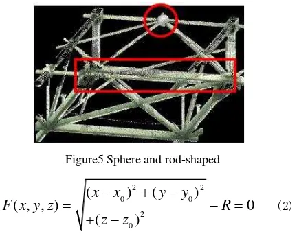
There are more rod-shaped and spheres in steel structure, and these characteristics are common used in actual construction survey. For the spherical characteristics, centers are usually extracted as feature points. For the rod-shaped components, the axis of its intersection can be seen as feature points.
The expression for sphere is:
2 2
0 0
2 0
(
)
(
)
( , , )
0
(
)
x
x
y
y
F x y z
R
z
z
(2)0
,
0,
0,
Rx y z
are spherical parameters, o( ,x y z0 0, 0)is spherical center, and
R
is spherical radius. The general form expresses is as follows:2 2 2
7 8 9 10
( , , )
0
F x y z
x
y
z
c x
c y
c z
c
(3)Among them, we have already known the radius of R, the center coordinates can be solved with least-square method.
Spatial cylinder could be expressed as:
2
0 0
2
0 0
2
0 0
[(
)
(
) ]
( , , )
[(
)
(
) ]
0
[(
)
(
) ]
x
x m
y
y l
F x y z
y
y n
z
z m
R
z
z l
x
x n
(4)
In equation (4) ,
x y z m n l
0,
0,
0, , , ,
R as rod-shaped surface parameters,o
( ,
x y z
0 0,
0)
says a point of rod-shaped surface axis,a
( , , )
m n l
is the unit vector of rod-shaped surface axis,R
is rod-shaped surface radius. There must be exists some noise points in the point-set selected for fitting the specific geometry. Generally, the fitting error of the specific geometry is
2
mm
. Figure 6 shows the rods intersection of the results and the extracted point in the point clouds.4. APPLICATION EXAMPLES
4.1 National Stadium (Bird’s Nest)
The Beijing National Stadium, known as the Bird's Nest is the main stadium for the 2008 Summer Olympics. The stadium is 330 meters long and 220 meters wide, and is 69.2 meters tall. The 250,000 square meters stadium is to be built with 36 km of unwrapped steel, with a combined weight of 45,000 tones. Twenty-four columns are installed firstly, and then the connection part are assembled on the ground and installed in the air. The ports of columns need to be measured and compared with connection part to make sure precise installation.
Figure7 shows the install field and point cloud of installed columns.
Figure5 Sphere and rod-shaped
(a) Box Interface
(b) Corner point
Figure4 feature extraction of box vetexs and corners
Figure 7 install field and point cloud of installed colomns 4.1.1 Registration of point cloud
Planar targets of HDS4500 are used in the registration and coordination transformation of point cloud. Figure 8 shows the control network of national stadium, targets used for transformation are stitched with reflectance patches and temp targets are set for registration of scan stations. The accuracy of registration is
3
mm
and transformation accuracy is
5
mm
, which could meets the pricision requirements.4.1.2 Extraction and comparison of feature points
Box-vertex points are being compared mainly and thickness is considered either. Connors feature are extracted mainly through intersection of planer patches and the fitting error of plane is
2
mm
. After extracting of feature points, the ports on ground is compared with the size left between columns and corrected according to the result.4.2 Slippage and installation quality monitoring of
national gymnasium roof construction
National gymnasium is one of three Main Venues of 29th Beijing Olympics Game. Total construction area is 80890 square meters reinforced concrete structure. The installation of the roof steel structure is done through installing the hinge and forward sliding of the ways. In the procedure of installation and sliding, high precision surveying and inspecting of the steel structure roof truss is necessary to keep the quality assurance of construction. National gymnasium roof consists of 14 trusses to support the buildings framework. The roof rack hinged by increasing and slipping from east to west, there are mainly three slides (see from Figure 9).
4.2.1 Combination of Targets and control points
The process of steel installation is generally sliding a welded frame and then next frame is left continually, at last the entire
frame is installed. So general observation period is selected at the time after a hinged sliding distance, and then another observation is made after next welded frame is finished. Two parts of the data are connected as a complete observation period.
Figure 10 point cloud of five frames
HDS3000 (Leica) is selected in actual observation, the furthest scanning distance of the scanner could reach 200~300m, with point accuracy 3~5mm in working zone, the scanning view is
360 270
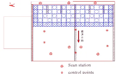
degrees; Scanning point interval is 10mm. According to demands of observation object, four relatively fixed observation sites is designed. Figure 10 shows the observation point cloud data when five frames are sided.4.2.2 Feature Points Extraction
Scanning targets is used in point cloud registration, which are acquried in the scanning progress and with the the precision 50 meters /
1.5
mm
. These points can be used either for registration of different scanstations or for transformation of coordinate system. All periods of point cloud could be transformed through the control points. The part of surveying is divided manually according to the target. The feature extracted includes spherial-shaped and rod-shaped. The fitting error is2
mm
. Some node adopts the rods intersection access to the actual feature nodes.4.2.3 Comparison with total station
Figure 9 Scanning sites and distribution of control points
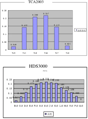
After all nodes summarized, the related node distribution can be seen clearly in Figure11. For checking the accuracy of the method, several nodes is selected to be measured by TCA2003, we can see that the two floats have the same trend and there are errors between corresponding nodes due to the position diversity of surveying points.
Figure11 data contrast between HDS3000 and TCA2003
4.3 4.3 Installation and Quality Monitoring of Steel-shell
of Tianjin West Station
Tianjin west station engineering is Asia's largest railway station building engineering, and it’s an important joint project in the establishing of Jinghu high speed railway. The construction area of this project is about 22.9 million square meters, and large span truss shell steel structure between east and west is 394.063
structure weight is 18000t. Station building engineering roof is arch structure .According to the site; it was divided into north area, central district and ascent part. The process of ascension of the total height is divided into three stages. In order to assure the final joining precision, it is necessary to measure all the interfaces before and after timely lifting, and the mosaic roof structure which maintains the steel frame should be taken overall deformation measurement before and after upload.
4.3.1 Combination of Multi-types Scanners
For reducing the effect of control connection error, Leica TDA5005 is used in control network surveying. The accuracy in ranging of instrument is 0.2mm and precision of angular accuracy is 0.5”. As shown in figure 13, seven control points are in first district in control network (T1 ~ T7).
Tianjin west station has more net shell ascending interface and the field occlusion is serious. For ensuring the accuracy and speed of measurement, combined mode scanning with medium-range (HDS6000) and remote-range scanner (Scanstation II) is used. Figure13 show Scanstation II sites, the big circles mainly scan the top interface, the residual are HDS6000 scanning sites. In the scanning process, remote scanner and control network can be measured jointly. To avoid splitting error accumulation in short-ranged sites, the scanning areas are separated into blocks; each block contains partial temporary control points so that the data could be transformed into the control coordination directly. According to the actual port scanning density,the actual interface determined as the scale 8mm point spacing.
4.3.2 Feature Points Extraction
Sphere targets are used in registration of point cloud. Each block is registered firstly, then the block could be transformed directly into the control network with control points, thus error accumulation can be avoided. The registration error is
5
mm
. In actual analysis, design coordinate system is used as reference coordinate system, the whole extraction of feature points and corresponding feature points design are matched with least-square adjustment method, thus the target point get unified with design coordinates. The transformed feature points that extracted could be made compare with designed corresponding feature points. As can be seen above, the data connection errorB13 C13 D13 E13 F13 G13 H13 J13 K13 L13 M13 N13 P13 Q13
高程
TCA2003
HDS3000
Figure12 Tianjin west station building
Port coordinate extraction mainly adopts the strategies on junction plane characteristics; planar fitting errors is
2
mm
, outside corner points is fitted.Data analysis using corresponding points of port to coordinate comparative analysis, the corresponding 4 fitting points are returned to the point cloud and compared with design position, specific port of welding deviation can be seen clearly.
4.3.3 Analysis of Port Deviation
All the ports feature points extracted are compared with design feature points in a form, and then the deviation of steel structure ports is displayed obviously. The deviation of ports is shown in Figure14; the ports whose deviation exceeds the threshold can be adjusted according to the check results.
Figure14 the deviation of a single row ports
5. CONCLUSION AND OUTLOOK
By analyzing the principle of LIDAR and engineering examples application, it is proved that LIDAR technology used in the monitoring of large steel construction is applicable with the characteristics of high-speed, precision and integrated monitoring. The technology can greatly reduce the workload of data collection and improve the analysis accuracy and comprehensive and efficient the guidance and monitoring of construction compare with the traditional surveying methods point by point.
The technique will be used more and more in the future architecture of construction, thus automatic feature point extraction would be efficient and precise data acquiring and registration automatically is also necessary for the technique. Acknowledgment
This paper was founded by Funding for Natural Science of Beijing (KZ200910016001);Funding Project for Academic Human Resources Development in Institutions of Higher Learning Under the Jurisdiction of Beijing Municipality (PHR20110511).
Reference
Xiangrui Guo, Hui Deng, Yuzhu Liu etc,2002, Roof–Stuff installation and monitoring of Guangzhou Stadium Journal of South China University of Technology September 2002 Vol.30 NO.9
Dean Luo,Guang Zhu, Li Lu, 2005, Integrated Deformation on Three-Dimensional Laser Images 2005 No.7
Yanmin Wang, Guoli Wang, 2009, LIDAR Technology in the Slippage and Installation Quality Monitoring of the National Indoor Stadium’s Roof Truss 2009.No.12.
Zhanyong Fan, Ming Yuan, Yong Yan, 2009, Analysis of accuracy use LIDAR scanning for steel structure of senatorial, Modern Surveying and Mapping Vol.32, No.2 Mar.2009 pp7-9.
O. Monserrat, M. Crosetto, 2008 Deformation measurement using terrestrial laser scanning data and least squares 3D surface matching. ISPRS Journal of Photogrammetry & Remote Sensing 63 (2008) 142–154
Alba, M., Fregonese, L., Prandi, F., Scaioni, M., Valgoi, P., 2006: Structural Monitoring of a Large Dam by Terrestrial Laser Scanning. International Archives of Photogrammetry, Remote Sensing and Spatial Information Sciences, 36 (Part 5).
Eleftherios TOURNAS, Maria TSAKIRI, 2008, Deformation Monitoring Based On Monitoring Based On Terrestrial Laser Scanner Point Cloud Registration, Symposium on Geodesy for Geotechnical and Structural Engineering LNEC, LISBON May 12-15.
Girardeau-Montaut, D., Roux, M., Marc, R., Thibault, G., 2005. Change detection on points cloud data acquired with a ground laser scanner. International Archives of Photogrammetry, Remote Sensing and Spatial Information Sciences 36 (Part 3/W19), 30–35.