DEVELOPMENT OF FOUR VISION CAMERA SYSTEM FOR A MICRO-UAV
G. Grenzdörffer, *, F. Niemeyer, F. Schmidt
a
Chair for Geodesy and Geoinformatics, Rostock University,18059 Rostock, Germany - [goerres.grenzdoerffer] [frank.niemeyer] [florian.schmidt2]@uni-rostock.de
Commission I, ICWG I/V
KEY WORDS: UAVs, Photogrammetry, BRDF, Remote Sensing, Correction, Calibration
ABSTRACT:
Due to regulations micro-UAV's with a maximum take-off weight of < 5kg are commonly bound to applications within the line of sight. An extension of the ground coverage is possible by using a set of oblique cameras. The development of such a multi camera system with a total weight of 1 kg under photogrammetric aspects is quite challenging. The introduced four vision camera system consists of four industrial grade oblique 1.3 mega pixel cameras (four vision) with 9 mm lenses and one nadir looking camera with a 6 mm lens. Despite common consumer grade cameras triggering and image data is stored externally on a small PC with a hard disk of 64 GB and a weight of only 250 g. The key question to be answered in this paper is, how good in a photogrammetric and radiometric sense are the small cameras and do they need an individual calibration treatment or is a single set of calibration parameters sufficient for all cameras?
* Corresponding author
1. INTRODUCTION
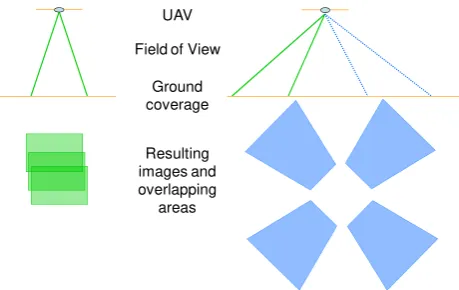
Due to regulations micro-UAV's with a maximum take-off weight of < 5kg are commonly bound to applications within the line of sight. The maximum flying height above ground allowed differs from country to country but it normally does not exceed 300 m (≈1000 ft). At this elevation a wide angle camera image covers an area of approximately 200 x 300 m. An extension of the ground coverage per image is possible by using an oblique camera. An oblique view covers a larger area, though not at the same scale throughout the image. Because of the intuitive human perception of the oblique view, photogrammetrists attention has returned to oblique images in the past years.
UAV
Field of View
Ground coverage
Resulting images and overlapping
areas
Figure 1: Ground coverage of an oblique "Four Vision" System compared to conventional nadir looking imagery
In the context of the developed system for the UAS vegetation studies are within the research focus. Oblique-looking images of vegetation surfaces provide additional advantages compared to the nadir looking perspective. A lower proportion of the soil background and a lesser amount of shadows in relation to the vegetation signal are visible in an oblique image. This improves the signal-to-noise ratio and a significant plant signal can be seen phenologically much earlier than in a comparable nadir shot. However, images acquired from a single oblique direction
are much more affected by the bidirectional reflection properties (BRDF) of the vegetation. This means that the reflection of the vegetation surface strongly depends on the viewing direction and the geometric relationship between the sun and the observer (camera), von Schönermark et al., 2004. Only with a synchronous recording of four cameras with 90° viewing directions, interfering effects (BRDF) can be computed, which otherwise makes the automated derivation of vegetation parameters almost impossible. First results of BRDF-measurements with a UAV are described in Grenzdörffer & Niemeyer, 2011.
The focus of this contribution is set to the radiometric and geometric calibration and especially important the inter calibration work of the five different cameras. The conducted research at the Chair for Geodesy and Geoinformatics at Rostock University is embedded in a project called “PFIFFIkus”. The general aim of the project is the development of a special payload for a UAV enabling photogrammetric nadir and oblique aerial images.
1.1 Oblique Imagery
Oblique images have historically been used for visualization and interpretation purposes, rather than for metric applications. Exceptions are the military sector and archaeology where oblique images have long been standard for reconnaissance purposes. Anyway, until recently oblique images were generally outside of the focus of photogrammetrists. They can thus be truly regarded as a new data source for photogrammetry and GIS.
Recently the market demanded more and more geometrically accurate images, e.g. for automatic texture mapping of 3D-City models, Karbø and Schroth, 2009. Therefore digital medium format cameras tightly coupled with a GPS/INS for precise direct georeferencing are used in current systems. To fully exploit the information from the oblique perspective, a minimum of four images from all sides have to be acquired and managed. For common airborne applications only multi head International Archives of the Photogrammetry, Remote Sensing and Spatial Information Sciences, Volume XXXIX-B1, 2012
medium format camera systems provide the necessary flexibility. For the professional acquisition of oblique images several companies developed multiple camera head solutions with five cameras (Petrie, 2009). This configuration is also called the "Maltese Cross" configuration. In such systems, one camera head provides a nadir view and the other four cameras provide the fixed oblique views in different directions, Figure 2. Within direct georeferencing the boresight alignment of such a multi-head camera system with overlapping images requires special treatment (Jacobsen, 2008, Wiedemann, 2009). The acquisition of oblique images requires several changes in the usual workflow for nadir (vertical) images, from survey planning to image processing and image analysis, Grenzdörffer et al., 2008.
System MIDAS – Track‘ Air Maltese cross
Image configuration Penta-DigiCAM
Figure 2: Oblique multi head medium format camera systems (Maltese Cross)
Digital medium format cameras are quite expensive, therefore alternatives were developed to reduce the number of cameras and still be able to acquire images from all directions, such as the Aero Oblique System (AOS) that has been recently built by Trimble (former RolleiMetric), Wiedemann, 2009.
2. THE FOUR VISION CAMERA SYSTEMS
It is quite clear that the above mentioned systems outweigh the maximum payload of a micro-UAV. Therefore a special light weight construction has to be developed with a total weight of 1 kg. Moreover additional general constraints for the development of the "four vision" camera system for a Micro-UAV apply:
• industrial grade programmable (video) cameras which are well suited for photogrammetric applications • low energy consumption
• flexible construction to allow for different viewing configurations
• on board data storage and GPS-based flight management
• ...
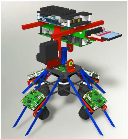
The developed multi head camera system consists of four diagonally-looking cameras (Four Vision) and an additional nadir looking camera. The five cameras are industrial grade digital frame cameras (1.3 Mpix CCD-chips, 15 f/s) with fixed lenses. 9 mm lenses were chose for the nadir looking images. The field of view (FOV) with 39° × 29° is quite limited to minimize hot spot effects. A wide angle 6 mm lens (FOV = 56° × 43°) was chosen for the nadir looking camera in order to get the same GSD from the nadir and oblique looking cameras. Typical ground resolutions range from 2.5 cm at an altitude of 50 m to 15 cm at the maximum altitude of 300 m.
Camera control and flight management is provided through a pico-board computer. The cameras are triggered by special GPS-based flight management software, developed by the
authors. The data is stored on a 64 GB-CF card. For further photogrammetric processing, the time synchronization and a precise triggering of the cameras are important. For further photogrammetric image processing the time of image exposure is recorded in the flight management system with a temporal resolution of 10 ms. The light weight carbon fiber construction weights no more than 80 g including a dark cover, which prevents unwanted incident sun light, Figure 3.
Figure 3: Construction drawing of the "Four Vision" camera system
In the flight planning for oblique aerial survey several special issues have to be considered. The image scale is not constant throughout the image. The ground sampling distance (GSD) is smaller in the foreground than in the background of the image. In the flight planning the altitude above ground and the viewing angle αy across the flight direction have to be defined. The viewing angle of the lens βy defines the minimum dmin and the maximum distance dmax from the aircraft to the area imaged, as well as the GSD.
In March 2012 the first successful test flight of the four vision camera system were conducted and a few aerial images were taken. However before any kind of data processing an intensive calibration of the cameras is necessary.
Figure 4: Schematic drawing of the UAV with newly developed multi head camera system "Four Vision" International Archives of the Photogrammetry, Remote Sensing and Spatial Information Sciences, Volume XXXIX-B1, 2012
3. CAMERA CALIBRATION
3.1 Camera selection and -calibration
After an intensive market survey the Crevis MV-CS27U USB 2.0 camera was selected, because the camera fulfils most of the above mentioned requirements. The most important technical camera parameters are summarized in Table 1.
Table 1: Technical data of the Crevis MV-CS27U
Parameter Property
Sensor 1280 x 1024 Pixel (= 1,3 MP),
1/2-inch-sensor (5,9 x 4,7 mm)
Pixel size 4,65 µm
Exposure time 1/60-1/2.500 s Focal length Fixed 9,65 mm Manual setting Focus, f-stop Min. image interval * Up to 15 f/s
Weight of camera system Camera 35 g + lens 45 g External data storage 64 GB CF-card (~3.000 images)
Lens adapter C-mount
*
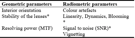
the minimum image interval can currently only be reached without saving the data on the hard driveA thorough calibration of the small cameras for the UAS application is very important. The calibration is not only important for the photogrammetric workflow but also for proposed the radiometric workflow of the images. During the examination of the image quality of digital CCD-imaging systems several parameters need to be investigated. In the following table some of the most important investigated geometric and radiometric parameters are listed.
Table 2: Investigated radiometric and geometric properties of Crevis MV-CS27U cameras
Geometric parameters Radiometric parameters Interior orientation Colour artefacts
Stability of the lenses* Linearity, Dynamics, Blooming *
Resolving power (MTF) Signal to noise (SNR)*
Vignetting * not presented in this paper
3.2 Geometric properties of the cameras
For further georeferencing the interior and exterior orientation needs to be known. The accuracy of the interior orientation is a classical quality criterion of a photogrammetric camera system. In our case with five identical cameras and lenses of the same type, three questions have to be answered:
1. How similar are the cameras and the lenses?
2. Can we apply a single set of orientation parameters to all cameras?
3. How is the temporal behavior of the interior orientation?
In order to get answers to the above mentioned questions, several test field calibrations were conducted. First the five different lenses were mounted onto one camera. This test shall provide an answer to the similarities of the lenses, especially the radial distortion and the focal length. Secondly one lens was tested on top of five different camera bodies. This shall give us an answer to the manufacturing accuracy of the camera bodies
and accuracy of the positioning of the CCD-sensor inside the camera, especially the principal point. Thirdly one lens and one camera were tested several times under different conditions. The interior orientation was determined with the software Australis 7.0.
All cameras reveal a significant barrel-shaped distortion. For the 9 mm lens the radial distortion at the image corner is as high as 32 pixels (≈ 150 µm). The 6 mm lens has a much higher radial distortion of up to 240 µm (≈51 pixels) in the image corners. The result of the first test with one camera and five lenses is shown in Figure 5. It clearly indicates that the four 9 mm lenses are very similar and manufactured with a high accuracy of a few microns. The focal length of the four 9 mm lenses differs very little as 5 µm. These differences are most probably due to differences in the mounting of the lenses.
Figure 5: Radial distortion of a Crevis Camera, equipped with 4 different lenses with c=9mm and one with c=6mm
The second test with one lens and five cameras shows that the principal point varies quite significantly (± 388 µm !!) between the different camera bodies, see also Figure 6.
Figure 6: Differences of principal point of investigated identical CREVIS cameras
To sum up: During further georeferencing a separate set calibration parameters for every camera is necessary. The interior orientation of the cameras is temporally quite stable; therefore a simultaneous calibration on every job / flight is not necessary unless we change the focus of the cameras.
3.2.1 Image motion – a crucial parameter for UAS flights
In order to obtain sharp images, the influences due to the (forward) motion of the UAS have to be considered. For common airborne applications the image motion u[µm] of an object is calculated with the following formula:
GSD GSD the ground resolution [m].
Applying this formula for common UAS (quadrocopter) flight at altitudes of 100 m and a speed of 15 m/s, an exposure time of 1/400 s is well sufficient. It turns out that this small exposure time is often not sufficient. This is due to the case, that especially multicopter UAS are constantly compensating winds with angular motions on one hand and on the other hand the compensation of these effects with stabilisation servos for the camera cause an additional significant amount of image motion.
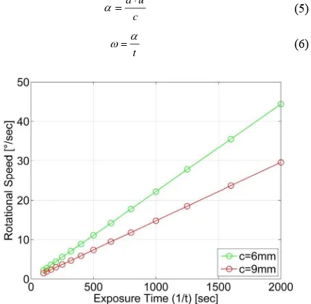
Based on several flights with our UAS (MD4-1000) under different conditions we found out, that the maximum rotational speed (ω) goes up to about 165°/s at blasts between 6 and 7 Bft. This corresponds to 0.46 rounds per second (RS). Such extreme rotations cause a significant amount of image motion, depending upon the exposure time, table 3.
Table 3 shows the relations between exposure time (left row = inverse value) and the rotational speed. The second row contains the angle α, at which the UAS will be rotated during exposure time, calculated with (2). Row three presents the according motion on the ground at a flight altitude of r = 25m (3). The corresponding pixel displacements for focal length of 6 m and 9 mm are calculated in row 4 and 5 with (4). The size of one pixel (sP) is given with 4.65 x 4.65 µm².
Table 3: Relation between exposure time and UAS-rotation induced pixel displacements
Using common exposure times of 1/500 – 1/1250 s images will become very blurry, because an image motion of 3 – 11 pixels will occur. For the photogrammetric image processing only the practical image motion is of relevance. The practical image motion is approximately half of the theoretical image motion. For a sharp representation the image motion (u) shall not
exceed < 0.5 pixel. Therefore, the limit for c = 6mm was exceeded 9 times and for c = 9mm 14 times. The question is now: How much rotational speed of the UAS is tolerable for an image motion of u < 0.5 pixel? The values in Figure 7 were calculated with (5) and (6).
a u
Figure 7: Maximum tolerable rotational speed of UAS
For an exposure time of 1/800 sec the allowed rotation speed for c = 9mm will be 11.8°/sec. These rotational speeds are common during flights under low wind conditions (2 - 3 Bft).
To sum up: image motion during a UAS flight with a quadrocopter largely depends on the wind conditions during the flight. Especially wind gusts will require a compensation of the UAS and the stabilized camera mount. For other UAS such fixed wing model planes the image motion due to the speed of the plane becomes more significant.
3.3 Radiometric properties of the cameras
The description of the image quality and the resolving power of a camera is not an easy task and cannot be reduced to a few numbers (Nasse,2008). Modern cameras have a manifold of different options that may influence the image quality. Also post processing steps influence the final quality of a digital image. Last but not least image quality varies with a different f-stop, focal length and exposure time. For aerial surveys with a UAS the f-stop is normally set to values between 4 - 7 and exposure times of 1/500 - 1/1.000 s. Accordingly the following image quality information is related to this configuration. For comparison reasons to medium format airborne applications image quality information of a Trimble AIC 45 is also provided.
3.3.1 Image Quality of the Crevis USB camera – modulation transfer function (MTF)
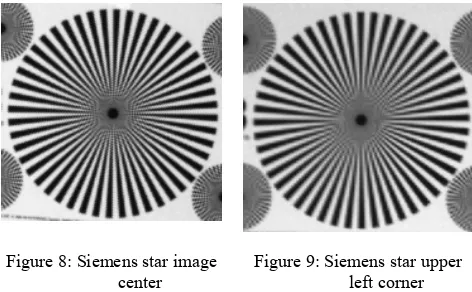
The measurement of the resolving power (RP) of an imaging system is generally determined by taking a photo of a special resolution test chart or a Siemens star. The computation of the maximum resolution in lp/mm using a Siemens star, e.g. with 96 sectors (48 sector pairs) is done with the following formula International Archives of the Photogrammetry, Remote Sensing and Spatial Information Sciences, Volume XXXIX-B1, 2012
d RP
⋅ =
π 48
(2)
where d = distance between the center of the Siemens star to the not resolved circle.
The measured values of the resolution with a Siemens star always depend upon the distance between the sensor and the object, because the non resolved part becomes bigger at further distances. For aerial surveys the absolute value of the RP less important to know, but the falloff toward the image corners and the influence of the lens and the differences between different camera systems and lenses. The radial falloff of the RP of the Crevis is about 25 %, as shown in figures 8 and 9.
Figure 8: Siemens star image center
Figure 9: Siemens star upper left corner
A contrast and distance independent description of the resolution is possible with a modulation transfer function (MTF). The 50%-value is often considered to be value of the resolving power. The values are described either in line pairs per mm (lp/mm) or in c/p (cycle/pixel). The unit lp/mm stands for an analogue small format standard value, which makes the MTF of different sensors comparable. For the conversion between c/p and lp/mm the following relation applies:
KB d
d DS
S S * S
2 * Pix * c/p /mm=
lp (3)
Where PixDS = number of pixels of the digital sensor (height), Sd = size of the digital sensor (height) [mm] and SKB = size of a analogue small film (24 mm).
For the evaluation of a lens not only the c/p values are of interest, but the whole curve progression is of importance. The measurement of the MTF was done with the software QuickMTF, Version 1.05. The distance between the camera and the target was approximately 2.3 m.
The nearly straight curve progression of the MTF up to the Nyquist boundary shows that the all frequencies are well represented. The c/p-values converted into lp/mm equated to a resolution of 26.1 lp/mm. At the image corner the resolving power is lower than in the image center 18.6 lp/mm which agrees nicely with the measurements of the Siemens star.
For an assessment and comparison reasons, additional tests with a medium format Trimble AIC 45 were conducted, which is used for aerial surveys. The medium format camera Trimble AIC 45) presents a resolving power of 0.39 c/p and thus comes quite close to the theoretical gradient of the MTF of a test image.
Figure 10: MTF of Crevis a the image center (f-stop 4,0)
Figure 11: MTF of Crevis a the image corner (f-stop 4,0)
Fine periodic samples define only a small part of the motif properties, which can be detected by human eyes. More important are edges and lines between two areas with different brightness and color. Most important are edges, which separate two regions of different brightness or color. The Line Spread Function (LSF) provides information how (sharp) a black to white edge is represented in the digital image. The transition between black and white is 2.22 pixels wide at the image center, Figure 12. Due to the fact that no integrated edge sharpening inside the camera is done, no negative values occur before and after the edge.
Figure 12: Line Spread Function (LSF) at image center
3.3.2 Vignetting
The CREVIS cameras shall be used for radiometric purposes and spectral BRDF measurements. Therefore it is quite important to know about the vignetting properties of the cameras. Vignetting thereby stand for a light intensity falloff at the corners of an image compared to the image center. Modern telecentric lenses can reduce the so called natural vignetting International Archives of the Photogrammetry, Remote Sensing and Spatial Information Sciences, Volume XXXIX-B1, 2012
quite nicely. However the optical vignetting remains a problem under certain circumstances. The optical vignetting is caused by multiple lens elements which are shaded by other elements in front of them, which then reduces the effective lens opening for off-axis incident light. The result is a gradual decrease in light intensity towards the outer parts of the image. Optical vignetting is quite sensitive to the lens aperture and can be minimized by a reduction in aperture.
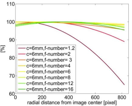
In our case the question is: what is the minimum or optimum f-stop of the cameras under which vignetting will not be significant? The determination of the vignetting effect is quite simple. A homogeneous and format filling diffuse reflecting object is put in front of the camera lens. Because artificial light sources are often inhomogeneous it is advisable to use sun light for the calibration. Thereby it is important to make sure that the imaging configuration does not allow for mirror reflection or unwanted hot spots effects. Figure 13 shows the measured vignetting effects of the 9 mm lens under different f-stops.
Figure 13: Vignetting of 9 mm lens at f-stops 1,4 - 16,0
For the 9 mm lens (Figure 13) shows a reduction of the vignetting with increasing f-numbers. The brightness falloff for f-numbers from 4 - 16 is significant and should be corrected. However it is lower than 10 % in the edges. For very low f-numbers the brightness falloff increases drastically.
Figure 14: Vignetting of 6 mm lens at f-stops 1,2 - 16,0
The 6 mm lens presents a different behavior. The figure illustrates that f-numbers from 4 – 6 show nearly no vignetting
(less than 2 %). Higher f-numbers from 8 – 16 reveal variations in brightness of 3 – 4 %. For images surveys which make very low f-numbers (1.4 – 2) necessary a vignetting reduction becomes a must.
4. CONCLUSION
The four vision camera system is currently still under development. The described calibration procedures are necessary steps. Compared to common consumer grade cameras the selected small and light weight industrial grade cameras provide repeatable geometric and radiometric calibration results. The differences to an ideal sensor are not so much of interest, because with known calibration parameters a high quality image processing chain can be developed in the future. Nevertheless it also became clear that, compared to airborne medium format cameras, the image quality of the investigated camera is much lower. An important result is the investigation of possible image motion. Due to the special behavior of an UAS in the air, standard formulas derived for airborne applications have to be reconsidered and extended.
BIBLIOGRAPHY
Grenzdörffer G., Guretzki, M., Friedlander, I., 2008: Photogrammetric image acquisition and image analysis of oblique imagery.- Photogrammetric Record, Vol. 23, Issue 124, 372 - 386
Grenzdörffer, G., Niemeyer, F. 2011: UAV based BRDF-measurements of agricultural surfaces with PFIFFikus.- Int. Arch. of the ISPRS, Vol. XXXVIII-1/C22, ICWG I/V UAV-g conference, Zurich, Switzerland. 2011, 6 p.
Karbø, N. Schroth, R., 2009: Oblique Aerial Photography: A Status Review.- In: Fritsch, D. [Ed.]: Photogrammetric Week `09: pp. 119 – 125
Jacobsen, K., 2008: Geometry of vertical and oblique image combinations.- 28th EARSeL Symposium. Istanbul, 2008, 8 p.
Nasse, N., 2008: How to Read MTF Curves.- http://www.zeiss.de/C12567A8003B8B6F/EmbedTitelIntern/C LN_30_MTF_en/$File/CLN_MTF_Kurven_EN.pdf (accessed 1.4.2012)
Petrie, G., 2009: Systematic Oblique Aerial Photography Using Multiple Digital Frame Cameras. Photogrammetric Engineering & Remote Sensing, 2/2009, S. 102-107.
Wiedemann, A., 2009: Photogrammetrische Schrägluftbilder mit dem Aerial Oblique System AOS.- DGPF Tagungsband 18: 8 p.
von Schönermark, M., Geiger, B., Röser, H.P., 2004: Reflection properties of vegetation and soil, 1st 7 ed.; Wissenschaft und Technik Verlag: Berlin, Germany, 352 p.
Acknowledgements
The presented research “PFIFFikus” is supported by TBI Technologie-Beratungs-Institut GmbH of the Ministry of Economics, Labour and Tourism Mecklenburg-Vorpommern under the grant number V230-630-08-TFMV-F041