LANE LEVEL LOCALIZATION; USING IMAGES AND HD MAPS TO MITIGATE THE
LATERAL ERROR
S. Hosseinyalamdarya∗, M. Petera
a
University of Twente, Faculty of ITC, Enschede, the Netherlands - (s.hosseinyalamdary, m.s.peter)@utwente.nl
Commission II, WG V/5
KEY WORDS:Lane Level Localization, Road Boundaries, Map Matching, Lane Matching
ABSTRACT:
In urban canyon where the GNSS signals are blocked by buildings, the accuracy of measured position significantly deteriorates. GIS databases have been frequently utilized to improve the accuracy of measured position using map matching approaches. In map match-ing, the measured position is projected to the road links (centerlines) in this approach and the lateral error of measured position is reduced.
By the advancement in data acquision approaches, high definition maps which contain extra information, such as road lanes are gener-ated. These road lanes can be utilized to mitigate the positional error and improve the accuracy in position.
In this paper, the image content of a camera mounted on the platform is utilized to detect the road boundaries in the image. We apply color masks to detect the road marks, apply the Hough transform to fit lines to the left and right road boundaries, find the corresponding road segment in GIS database, estimate the homography transformation between the global and image coordinates of the road boundaries, and estimate the camera pose with respect to the global coordinate system.
The proposed approach is evaluated on a benchmark. The position is measured by a smartphone’s GPS receiver, images are taken from smartphone’s camera and the ground truth is provided by using Real-Time Kinematic (RTK) technique. Results show the proposed approach significantly improves the accuracy of measured GPS position. The error in measured GPS position with average and standard deviation of 11.323 and 11.418 meters is reduced to the error in estimated postion with average and standard deviation of 6.725 and 5.899 meters.
1. INTRODUCTION
1.1 Map Matching
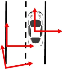
The emerging intelligent technologies, such as autonomous driv-ing, require accurate pose estimation of the platform. The pose of platform should be accurately estimated with respect to the road lanes, other vehicles, and the global coordinate system. There-fore, not only the pose of platform should be estimated in the global coordinate system, it should also be estimated with respect to other local coordinate systems, such as road coordinate system and the coordinate system of other platforms. Figure 1 schemati-cally shows the platform coordinate system, road coordinate sys-tem, and global coordinate system.
Figure 1. The platform, road and global coordinate systems are schematically demonstrated by red arrows.
∗Corresponding author
The ubiquitous outdoor localization technology is Global Navi-gation Satellite System (GNSS) positioning. The GNSS satellites cover the whole world and therefore, the position of platform can be measured everywhere. There are a number of shortcomings in GNSS positioning: centimeter-level accuracy of GNSS position-ing requires additional instruments and infrastructure and there-fore, high accuracy GNSS positioning is costly. In addition, it requires clear sky view and therefore, the accuracy of GNSS po-sitioning is deteriorated in urban canyon where buildings block GNSS signals.
In the absence of GNSS signals, Inertial Measurement Units (IMUs) are applied to bridge gaps between GNSS outages. How-ever, it imposes additional cost to the system and IMU’s error grows over time.
Map matching has been frequently applied to improve the accu-racy of GNSS positioning. If a Geo-spatial Information System (GIS) is available, the measured GPS position can be projected into the center of road links in the GIS database. Therefore, the lateral error (perpendicular to road link) of measured GPS posi-tion is mitigated, but the longitudinal error (along road link) of measured GPS position remains a problem.
In this paper, High Definition (HD) maps are applied to estimate the location of platform. Therefore, the lateral error is signifi-cantly reduced despite the fact that longitudinal error remain in-tact.
1.2 Lane Matching
and possibly its entrances from and exits to other roads. Tradi-tional map matching approach in which the position is projected into the road centerline is not sufficiently accurate for emerging applications, such as autonomous driving. Therefore, HD maps, with delineated road boundaries and lanes, are applied to project the position into the correct lane and improve the lateral accuracy of GNSS positioning.
In order to detect the lane the platform is in, a camera should be mounted on the platform and images should be utilized. In addition, the road segment corresponding to the current location of platform should be retrieved from the GIS database. Using the image content and road segment, the position of platform is estimated using homography transformation.
Unfortunately, traffic features are different from a country to an-other. In the United States, the left road boundaries are delineated with yellow solid lines and the right one is white, white solid lines represent road boundaries in Germany, and there are various road marks to indicate the road boundaries in other countries. In ad-dition, the road lanes may be represented by white dashed lines or solid lines. Furthermore, the road lanes may not be marked and the lane boundaries may be fuzzy. In conclusion, provid-ing a solution to lane matchprovid-ing for all countries and situations is cumbersome. We focus on the solution for a regular highway in the United states, but the proposed approach can be modified for other countries and road types. Figure 2 shows four different road marks in various countries.
Figure 2. The road marks are different depending on the road type and the regulations of the country the road located. The road boundaries can be marked in yellow or white and solid or
dashed lines. Some roads may not have proper road marks (courtesy of pexels.com).
1.3 Literature Review
A number of researchers focus on the use of map matching for urban canyon, where the GNSS signal is blocked. Chu et al. ap-ply map matching to the GPS/IMU integration and improve the IMU drifts (Chu et al., 2013). Map matching is applied in the situations where the GNSS signals are frequently lost (Jimenez et al., 2016). In addition, the map matching algorithm is investi-gated for low sampling rate GPS receivers in (Lou et al., 2009). In (Pereira et al., 2009), the authors propose an off-line map match-ing algorithm to handle the incompleteness in GIS databases.
Since map matching faces many uncertainties in reality, fuzzy logic has been frequently utilized to handle these uncertainties.
The researchers use fuzzy logic to identify the correct road link (Quddus et al., 2006). Balazadegan and Gao also apply fuzzy logic to find the correct link and use map matching to improve the accuracy of multi-sensor integration (Balazadegan and Gao, 2016). In (Syed and Cannon, 2004), a high sensitivity GPS receiver and IMU are applied to localize the platform in ur-ban canyon and the results are utilized for map matching. Ren and Karimi use the fuzzy logic based map matching to navigate wheelchairs (Ren and Karimi, 2012).
Deep Neural Network (DNN) has been applied in some research to improve the results of map matching. Kim and Lee utilize convolutional neural network (CNN) and RANdom SAmpling Consensus (RANSAC) to robustly detect the lanes of road (Kim and Lee, 2014). Pazhayampallil and Kuan apply deep learning to detect the lanes and localize the platform (Pazhayampallil and Kuan, 2013). DeepLanes uses side looking cameras to detect the lanes and position the vehicle between the lanes (Gurghian et al., 2016). In (Newson and Krumm, 2009), Newson and his col-leagues utilize Hidden Markov Model (HMM) to find the most likely position of the platform in the network. An open source software is provided for map matching using HMM (Mattheis et al., 2014).
The lane matching and localization has recently emerged by the advancement of more accurate maps. In (Rabe et al., 2016), GPS, camera, and other vehicular sensors are integrated to de-tect the correct lane and improve the accuracy of positioning. Re-searchers apply point cloud and GPS data to achieve the lane level positioning accuracy (Mattheis et al., 2014). In (Tanaka, 2016), the author uses only the images from visited sites and apply map matching to improve the results of image based navigation.
2. METHODOLOGY
In this paper, four coordinate systems are utilized: image coor-dinate system, platform coorcoor-dinate system, road coorcoor-dinate sys-tem, and global coordinate system. It is assumed the image and platform coordinate systems are calibrated and their boresight and lever-arm are determined. Therefore, if the transformation between the image and road coordinate systems are estimated, the transformation between platform and road coordinate systems can be calculated. We propose an approach to calculate the trans-formation between image and road coordinate system using im-age processing approaches.
Since definition of the road coordinate system depends on the road segment where the platform is located, we propose an ap-proach to find the corresponding road segment within the GIS database. Therefore, the image coordinate system can be trans-ferred to the global coordinate system and consequently, the pose of platform is calculated with respect to the global coordinate system.
2.1 Local and Global Coordinate Systems
In this section, the local and global coordinate systems are de-fined. The image coordinate system is centered at the left-up cor-ner of the image, the x-axis is in the direction of column pixels and the y-axis is in the direction of row pixels.
column pixels where the rows are decrementing. It is a right-handed coordinate system.
The platform coordinate system is located at the phase center of GNSS receiver, mounted on the platform. Its x-axis is aligned with the direction of the platform’s forward motion. The z-axis of platform coordinate system is aligned upward and the y-axis is aligned in the way it creates a right-handed coordinate system.
The angle between the camera and platform coordinate systems is called boresight and the displacement vector between these two coordinate systems is called arm. The boresight and lever-arm are determined in the calibration stage. The lever-lever-arm can be neglected since the GPS receiver and camera are located inside the smartphone. In addition, the angle between x-axis of plat-form and z-axis of camera are assumed to be zero. Therefore, an arbitrary position in the camera coordinate system is transformed to the platform coordinate system, such that:
xp=R3(−
π
2)R1(−
π
2)xc (1)
where xc= a point in camera coordinate system xp= a point in platform coordinate system R1= rotation around x-axis of
camera coordinate system R3= rotation around z-axis of
camera coordinate system.
The road coordinate system is located at the left road boundary of the current road segment. Its x-axis is aligned with the direction of left road boundary toward forward motion of platform. The z-axis is the normal vector of the road surface and the y-axis is aligned in the way it creates a right-handed coordinate system.
The transformation between the platform and road coordinate systems depends on the dynamic of platform. If the ruggedness of road is neglected, the transformation between these coordinate system is estimated, such that:
xr=R3(α)xp (2)
where xp= a point in platform coordinate system xr= a point in road coordinate system R3= rotation around z-axis of
platform coordinate system α= the angle between x-axis of these coordinate systems.
The road features stored in the GIS database are in the global ordinate system. The global coordinate system is a geodetic co-ordinate system with the World Geodetic System 1984 (WGS84) ellipsoid. In other words, the features are represented in latitude, longitude, and height. The transformation between local nate system, such as road coordinate system, and global coordi-nate system is given in (Jekeli, 2001).
As a result, we determine the platform’s pose with respect to the global coordinate system after the transformation between cam-era coordinate system and road coordinate system is estimated.
2.2 Finding the Corresponding Road Segment
The HD maps are humongous since they contain the details of roads for a large area. Roads are multi-lines and can be as long as a few hundred kilometers. Usually, the left and right road bound-aries are represented by two multi-lines. The road marks sep-arating lanes are also shown by multi-lines. A single line of a multi-line feature is called road segment. The road segment that is the closest to the platform should be selected. When this road segment is found, every feature represented by a multi-line is re-duced to a line corresponding to the road segment.
It is impossible to find the corresponding road segment without GNSS positioning. In the proposed approach, we first reduce the search space for the corresponding road segment to a few candi-dates. A circular buffer centered at measured GPS position is ap-plied to the road features in the GIS database and the vertexes of multi-lines which fall outside the buffer are removed. Therefore, the number of candidates for the road segment significantly re-duces. Among these candidates, the Euclidean distance between measured GPS position and each candidate is calculated and the one with minimum distance to the measured GPS position is se-lected. When the corresponding road segment is selected, the other attributes of the road segment, such as color or functional-ity of each road mark are retrieved, in addition to the geometrical properties of the road mark.
Whenever the platform moves, the road segment should be re-selected. Most of the time, previously selected road segment will be the corresponding road segment at the current time. There-fore, if the correct road segment is found for the current time, the current road segment should be compared to the next road seg-ment for the next time and the one with minimum distance to the measured GPS position should be selected.
In traditional map matching, the measured GPS position is jected into the center of corresponding road segment. In our pro-posed approach, we use the road boundaries of the corresponding road segment and find the position of platform between the road boundaries. Therefore, our proposed approach suppresses lateral error better than the traditional map matching.
2.3 Road Boundary Detection
In order to localize the pose of platform, we exploit the road boundaries. There are a number of advantages to use road bound-aries rather than road lanes: The road boundbound-aries are solid lines and therefore, they are prominent features and easier to detect; The marks of the road lanes are dashed and can be occluded by other vehicles; The lanes are not separated with road marks in some roads and lane boundaries are fuzzy.
remains. The white mask is constructed by masking high satura-tion. The masked white color is shown in Figure 3 (up-right). In order to separate the left and right road boundaries, the image is divided into the left and right parts and the Hough transform is applied to left and right parts to fit a line to each road boundary. The fitted lines to road boundaries are shown in 3 (down-right).
Figure 3. The original image (up-left) is masked by white and yellow colors (up-right and down-left), the Hough transformation is applied to binary images and the left and right
road boundaries are modeled by two lines (down-right).
Theoretically, a line passes through every two pixels on the left and right road boundaries. The Hough transform detect the line that passes through most of pixel pairs and therefore, it detects the most prominent line.
2.4 Lane Level Localization
Since the road surface is a plane, there is a homogrpahy transfor-mation between the projective geometry of image space and Eu-clidean geometry of object (road) space. The left and right road boundaries are parallel lines in the object space, but they intersect at the point of infinity under projective geometry in the image space. The homography transformation can be applied to con-vert the projective view in the image space into the object space. When the homogrpahy transformation is estimated, the camera pose can be calculated with respect to the road if the camera is calibrated.
Theoretically, at least four corresponding points or (nonparallel) lines should be known in the image and object spaces in order to estimate the homography transformation. Unfortunately, only two lines, the left and right road boundaries, are known in the image and object spaces. Therefore, the homography estimation cannot be performed without additional assumptions.
Let’s assume the first visible point on the road isDmeters far from the camera. We assumeDis 5 meters considering the hood of vehicle blocks the closer points on the road. If a horizontal line is drawn in the image which passes through this point, it intersects with the left and right road boundaries atp1andp2. Let’s assume
the distance betweenp1 andp2isd. We can draw a horizontal
line in the way it intersects the left and right road boundaries at p3andp4and the distance between these points is d2. It can be
easily proven that the distance of this line from the camera is2D, assuming the road width does not significantly change.
These assumptions may not be accurate, but they only affect the longitudinal component of the homography estimation and its lat-eral component is sufficiently accurate.
After these assumptions, we have four corresponding points in the image and object spaces and the homography transformation is estimated using these points. If the camera is calibrated and its intrinsic parameters are known, the homography transformation is decomposed into its rotation matrix and translation vector.
3. EXPERIMENT
Our proposed approach is evaluated using a benchmark provided by ”Lane Level Localization, University Grand Challenge” (Lane Level Localization, University Grand Challenge, 2016). The po-sition of platform is measured using the GPS receiver inside a smartphone. The accuracy of the measured GPS position is poor and its error exceeds 50 meters in some regions. The ground truth of platform’s position is measured using Real-Time Kinematic (RTK) technique.
The smartphone is mounted inside a vehicle and its camera records a sequence of images of the road. The images have
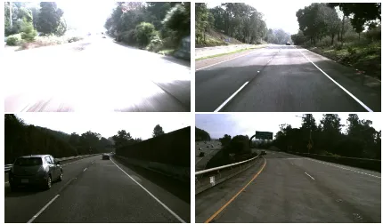
800×600resolution and are taken in 10Hz. The focal length is fixed, but the camera calibration parameters are not accurate. The images suffer from motion blur since the platform is in motion. In addition, the illumination is not uniform and some images are overexposed or underexposed. Some of the problematic images are shown in Figure 4.
Figure 4. There are a number of challenges in the road boundary detection. The images can be underexposed or overexposed (up-left); the shadow can lead to incorrect lane detection since
the brightness of image abruptly changes (up-right); the road boundaries are occluded by other vehicles (down-left); The road
can be curvy and fitting a line to the curvy road may be cumbersome (down-right).
The provided HD map includes road boundaries, road lanes, road entrances and exits, curbs, and crash barriers. These objects are represented as multi-lines with several attributes such as color, type, and functionality. The HD map features are highly accurate and contain detailed information. Table 1 shows the road bound-aries and lanes in the GIS database.
The data was collected over 20 kilometers of US highways. The highway has multiple lanes, marked by dashed white lines and the quality of road marks is good. The platform changes its lane on a few occasions. Figure 5 demonstrates the GPS trajectory in red and ground truth in green.
4. RESULTS
Table 1. A road segment in JSON format stored in the GIS database.
”id”: ”1”, ”lines”: [
{”id”: ”a66731099”, ”type”: ”boundary”, ”function”: ”left”, ”color”: ”NULL”, ”polyPoints”: [
{”coordinates”: 37.849781,-122.23068,119.511},
{”coordinates”: 37.849752,-122.23056,119.269}]},
{”id”: ”07bc237a4”, ”type”: ”solid”, ”function”: ”left”, ”color”: ”yellow”, ”polyPoints”: [
{”coordinates”: 37.84993,-122.23069,119.465},
{”coordinates”: 37.849733,-122.23051,119.185}]},
{”id”: ”e0e95a051”, ”type”: ”dashed”, ”function”: ”middle”, ”color”: ”white”, ”polyPoints”: [
{”coordinates”: 37.849732,-122.23064,119.353},
{”coordinates”: 37.849027,-122.23055,119.108}]},
{”id”: ”a5950c220”, ”type”: ”solid”, ”function”: ”right”, ”color”: ”white”, ”polyPoints”: [
{”coordinates”: 37.849714,-122.23067,119.343},
{”coordinates”: 37.849224,-122.23061,119.015}]},
{”id”: ”6c196c98b”, ”type”: ”boundary”, ”function”: ”right”, ”color”: ”NULL”, ”polyPoints”: [
{”coordinates”: 37.849451,-122.2307,119.253},
{”coordinates”: 37.8484,-122.23067,119.203},
{”coordinates”: 37.849744,-122.2306337,119.006}]}],
Figure 5. The smartphone’s GPS data has been shown in red and ground truth in green. The error of measured GPS position
exceeds 50 meters in some regions.
using our proposed approach. These positions are subtracted from the ground truth and the position error is calculated in every epoch. The results are shown in Figure 6. The measured GPS position error is shown in red and the estimated position error in our proposed approach is shown in blue.
The results show the error of measure GPS position is signifi-cantly reduced and therefore, the position accuracy is improved using our proposed approach. In other words, the proposed ap-proach mitigates the lateral error of the measured GPS position. However, the longitudinal error in the measured GPS position is not necessarily reduced.
Table 2. The measured GPS position error using smartphone’s GPS receiver and the estimated position error using our proposed approach are compared in this table. The mean and standard deviation of error position are given for each approach.
error in error in
measured position estimated position mean
[m] 11.323 6.725
standard deviation
[m] 11.418 5.899
The mean error in the measured GPS position and the estimated position using our proposed approach are 6.725 and 11.323 me-ters. Their standard deviations are 5.899 and 11.418 meme-ters. The results are given in Table 2.
The longitudinal error in the measured GPS position may lead to the incorrect GIS segment detection. The wrong choice of the GIS segment may introduce lateral error in estimated position. For this reason, the estimated position using our proposed ap-proach has larger error than the measured GPS position in a few epochs.
There are a few sharp jumps in the error of measured GPS po-sition around 80 and 160 seconds. In these areas, the GPS sig-nals are blocked by trees and bridges and therefore, the error of measured GPS position is large due to the signal blockage and bad geometry of the visible satellites. The proposed approach significantly mitigates these jumps, but it cannot plateau the po-sition error. The proposed approach improves the lateral error, but does not necessarily improve the longitudinal error. There-fore, the longitudinal component of the position error remains in the estimated position. There are some approaches to mitigate the longitudinal error. For instance, traffic signs can be utilized to suppress the longitudinal error and improve the position accuracy.
The measured GPS position has higher variance and it irregularly changes. The estimated position using the proposed approach shows more predictive behavior than the measured GPS position. This predictable behavior is crucial for statistical models such as the Kalman and particle filters. Therefore, the statistical models are more robust using the estimated position.
The estimated position using our approach shows superior perfor-mance over the measured GPS position. However, the error in the estimated position does not go lower than 3 meters. It is because of the fact that the longitudinal error still exists in the estimated position.
5. CONCLUSION
Figure 6. The error of measured GPS position is shown in red and the estimated position error is shown in blue. The results show our proposed approach can significantly improve the
position accuracy.
The proposed approach has been applied for the measurements of a smartphone’s GPS receiver and the results of our proposed ap-proach shows superior performance over measured GPS position. In addition, jumps in the position error are significantly mitigated using our proposed approach.
REFERENCES
Balazadegan, Y. and Gao, Y., 2016. Multi-Sensor Map Match-ing Techniques for Autonomous Land Vehicle Navigation. PhD thesis, University of Calgary.
Chu, H. J., Tsai, G. J., Chiang, K. W. and Duong, T. T., 2013. Gps/mems ins data fusion and map matching in urban areas. Sen-sors13(9), pp. 11280–11288.
Gurghian, A., Koduri, T., Bailur, S. V., Carey, K. J. and Murali, V. N., 2016. Deeplanes: End-to-end lane position estimation us-ing deep neural networks. In:The IEEE Conference on Computer Vision and Pattern Recognition (CVPR) Workshops.
Jekeli, C., 2001.Inertial navigation systems with geodetic appli-cations. Walter de Gruyter.
Jimenez, F., Monzon, S. and Naranjo, J. E., 2016. Definition of an enhanced map matching algorithm for urban environments with poor gnss signal quality.Sensors.
Kim, J. and Lee, M., 2014. Robust lane detection based on convolutional neural network and random sample consensus. In: Neural Information Processing: 21st International Confer-ence, ICONIP 2014, Vol. 8834, Springer International Publish-ing, Cham, pp. 454–461.
Lane Level Localization, University Grand Challenge, 2016. http://conference.eng.unimelb.edu.au/its-gc/.
Lou, Y., Zhang, C., Zheng, Y., Xie, X., Wang, W. and Huang, Y., 2009. Map matching for low-sampling-rate gps trajectories. In: ACM International Conference on Advances in Geographic Information Systems (SIGSPATIAL) GIS 2009.
Mattheis, S., Al-Zahid, K. K., Engelmann, B., Hildisch, A., Holder, S., Lazarevych, O., Mohr, D., Sedlmeier, F. and Zinck, R., 2014. Putting the car on the map: A scalable map matching system for the open source community. In:44. Jahrestagung der Gesellschaft fur Informatik, Informatik 2014, Big Data - Kom-plexitat meistern, pp. 2109–2119.
Newson, P. and Krumm, J., 2009. Hidden markov map match-ing through noise and sparseness. In: Proceedings of the 17th ACM SIGSPATIAL International Conference on Advances in Ge-ographic Information Systems, GIS ’09, pp. 336–343.
Pazhayampallil, J. and Kuan, K. Y., 2013. Deep learn-ing lane detection for autonomous vehicle localization. http://cs229.stanford.edu/proj2013/.
Pereira, F. C., Costa, H. and Pereira, N. M., 2009. An off-line mapmatching algorithm for incomplete map databases.European Transport Research Review1(3), pp. 107–124.
Quddus, M. A., Noland, R. B. and Ochieng, W. Y., 2006. A high accuracy fuzzy logic based map matching algorithm for road transport. Journal of Intelligent Transportation Systems10(3), pp. 103–115.
Rabe, J., Meinke, M., Necker, M. and Stiller, C., 2016. Lane level map matching based on optimization. In:2016 IEEE 19th International Conference on Intelligent Transportation Systems (ITSC), pp. 1155–1160.
Ren, M. and Karimi, H. A., 2012. A fuzzy logic map matching for wheelchair navigation.GPS Solutions16(3), pp. 273–282.
Syed, S. and Cannon, M., 2004. Fuzzy logic based-map match-ing algorithm for vehicle navigation system in urban canyons. In:
Proceedings of the 2004 National Technical Meeting of The In-stitute of Navigation, ION ’04, pp. 982–993.