U.S. Department of Transportation
Federal Highway Administration
Steel Bridge Design Handbook
Selecting the Right Bridge Type
Publication No. FHWA-IF-12-052 - Vol. 5
November 2012
Notice
This document is disseminated under the sponsorship of the U.S. Department of Transportation in the interest of information exchange. The U.S. Government assumes no liability for use of the information contained in this document. This report does not constitute a standard, specification, or regulation.
Quality Assurance Statement
The Federal Highway Administration provides high-quality information to serve Government, industry, and the public in a manner that promotes public understanding. Standards and policies are used to ensure and maximize the quality, objectivity, utility, and integrity of its information. FHWA periodically reviews quality issues and adjusts its programs and processes to ensure continuous quality improvement.
Steel Bridge Design Handbook:
Selecting the Right Bridge Type
Publication No. FHWA-IF-12-052 - Vol. 5
November 2012
Technical Report Documentation Page 1. Report No.
FHWA-IF-12-052 - Vol. 5
2. Government Accession No. 3. Recipient’s Catalog No.
4. Title and Subtitle
Steel Bridge Design Handbook: Selecting the Right Bridge Type
5. Report Date
13. Type of Report and Period Covered
Technical Report
March 2011 – November 2012
14. Sponsoring Agency Code
15. Supplementary Notes
This module was edited in 2011 by HDR Engineering, Inc., to be current with the AASHTO LRFD Bridge Design Specifications, 5th Edition with 2010 Interims.
16. Abstract
One of the initial choices to be made by the bridge designer is to select the most appropriate bridge type for the site. While this choice is not always straightforward, selecting the right structure type is probably the important aspect of designing a cost-effective bridge. This particular module provides bridge designers with the tools to select the right bridge type for the given site. Bridge types discussed included rolled steel beam, steel plate girder, trusses, arches, cable-stayed, and suspension bridges.
17. Key Words
Steel Bridge, Bridge Type, Span Length, Economics, Constructibility
18. Distribution Statement
No restrictions. This document is available to the public through the National Technical Information Service, Springfield, VA 22161.
Form DOT F 1700.7 (8-72) Reproduction of completed pages authorized
Steel Bridge Design Handbook:
Selecting the Right Bridge Type
Table of Contents
FOREWORD ... 1
1.0 INTRODUCTION ... 3
1.1 Required Span Lengths ... 3
1.1.1 Owner Desires ... 3
1.1.2 Hard Requirements ... 3
1.1.3 Existing Constraints ... 3
1.1.4 Other Constraints ... 4
2.0 BRIDGE TYPES ... 5
2.1 Rolled Beam Bridges ... 5
2.2 Welded Plate Girder Bridges ... 5
2.3 Trusses ... 7
2.4 Arches ... 12
2.5 Cable-Stayed ... 15
2.6 Suspension Bridges ... 18
3.0 ECONOMICS ... 20
4.0 CONSTRUCTABILITY ... 21
4.1 Rolled Beams/Welded Plate Girders ... 21
4.2 Trusses ... 21
4.3 Arches ... 22
4.4 Cable-Stayed Bridges... 22
4.5 Suspension Bridges ... 22
ii
List of Figures
Figure 1 Photo of a typical multi girder system with x-type intermediate cross frames and
stay-in-place formwork used for constructing the deck slab ... 6
Figure 2 Photo of a typical girder substringer system showing a stringer sitting on top of cross frames ... 7
Figure 3 Photo of the Forrest Hill Bridge over American River's north fork, Auburn, California 8 Figure 4 Photo of the Chelyan Bridge over Kanawha River, Kanawha County, West Virginia ... 9
Figure 5 Photo of the Glenwood Bridge over Monongahela River, Pittsburgh, Pennsylvania ... 10
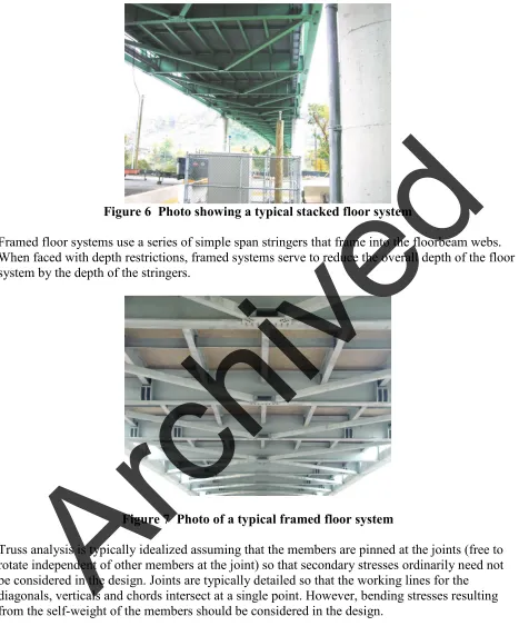
Figure 6 Photo showing a typical stacked floor system ... 11
Figure 7 Photo of a typical framed floor system... 11
Figure 8 Photo of the New River Gorge Bridge near Fayetteville, West Virginia ... 13
Figure 9 Photo of the I-470 Bridge over Ohio River, Wheeling, West Virginia ... 13
Figure 10 Photo showing the erection of the I-79 Bridge over the Ohio River, Pittsburgh, Pennsylvania ... 15
Figure 11 Photo of the Sydney Lanear Bridge, Brunswick, Georgia ... 16
Figure 12 Photo of the William H. Natcher Bridge over Ohio River near Owensboro, Kentucky ... 16
Figure 13 Photo of the Normandy Bridge over Seine River near Le Havre, France ... 17
Figure 14 Photo of the Sunshine Skyway Bridge, Tampa, Florida ... 17
Figure 15 Photo of the Golden Gate Bridge, San Francisco, California... 19
FOREWORD
It took an act of Congress to provide funding for the development of this comprehensive handbook in steel bridge design. This handbook covers a full range of topics and design examples to provide bridge engineers with the information needed to make knowledgeable decisions regarding the selection, design, fabrication, and construction of steel bridges. The handbook is based on the Fifth Edition, including the 2010 Interims, of the AASHTO LRFD Bridge Design Specifications. The hard work of the National Steel Bridge Alliance (NSBA) and prime consultant, HDR Engineering and their sub-consultants in producing this handbook is gratefully acknowledged. This is the culmination of seven years of effort beginning in 2005.
The new Steel Bridge Design Handbook is divided into several topics and design examples as follows:
• Design Example: Three-span Continuous Straight I-Girder Bridge
• Design Example: Two-span Continuous Straight I-Girder Bridge
• Design Example: Two-span Continuous Straight Wide-Flange Beam Bridge
• Design Example: Three-span Continuous Straight Tub-Girder Bridge
• Design Example: Three-span Continuous Curved I-Girder Beam Bridge
• Design Example: Three-span Continuous Curved Tub-Girder Bridge
These topics and design examples are published separately for ease of use, and available for free download at the NSBA and FHWA websites: http://www.steelbridges.org/, and
http://www.fhwa.dot.gov/bridge, respectively.
2 The contributions and constructive review comments during the preparation of the handbook from many engineering processionals are very much appreciated. The readers are encouraged to submit ideas and suggestions for enhancements of future edition of the handbook to Myint Lwin at the following address: Federal Highway Administration, 1200 New Jersey Avenue, S.E., Washington, DC 20590.
M. Myint Lwin, Director Office of Bridge Technology
1.0 INTRODUCTION
One of the initial choices to be made by the designer is to select the most appropriate bridge type for the site. While this choice is not always straightforward, selecting the right structure type is probably the important aspect of designing a cost-effective bridge.
1.1 Required Span Lengths
Various types of bridge superstructures provide efficient solutions for different span
arrangements. There are many possible reasons for choosing particular span lengths for bridges, some of which are discussed below.
1.1.1 Owner Desires
In many cases, the owner’s desires will drive the selection of the bridge type. Some owners tend to push their bridges toward the shortest spans possible, with an eye toward allowing a choice of materials or to prefer a specific material type.
Owners will occasionally choose a bridge because they desire to construct a specific bridge type at a location. In some cases these desires come directly from the owner, but often public opinion influences the selection of the bridge type, particularly for long span bridges.
Occasionally, an owner will prescribe a certain bridge type for reasons of perceived prestige. The choice may be made specifically to design a bridge type that has not been done by that owner, to design a certain bridge type with a record span length, or to create a signature structure.
1.1.2 Hard Requirements
One critical requirement that often controls the main span lengths for water crossings is navigational clearance. The U. S. Coast Guard is generally the controlling agency regarding required span lengths for navigable inland waterways
.
Another non-negotiable controller of bridge span lengths can be defined by environmental commitments. Given the increased sensitivity to minimizing adverse environmental impacts, there have been many cases where the span arrangements have been set to meet environmental commitments.
1.1.3 Existing Constraints
Locations of existing constraints often control the span arrangements for new structures. For new, high-level structures, the locations of existing features that are being crossed by the new structures may control certain span lengths or span arrangements. This situation may occur where expanded interchanges are being constructed on or near the site of existing interchanges where the original structures will be retained or used for staging during construction. The location of existing surface roadways often controls span arrangements for new bridges.
4 Occasionally it is more cost-effective to move the surface roadways to accommodate the new bridge, but in congested urban areas this is rarely possible.
Another constraint encountered by designers/owners is railroads. There are significant costs associated with moving tracks or interrupting rail service to accommodate construction of new bridges. It is often beneficial to increase span lengths to minimize impacts to the railroads. Since the railroads are for-profit enterprises, they tend to be very protective of their facilities in order to maintain profitability.
1.1.4 Other Constraints
Site access may control the choice of span arrangements for structures in certain cases. When constructing bridges over wide, deep valleys, it is sometimes advantageous to increase span lengths to eliminate costly piers. In some cases, deck structures such as trusses or arches may become economical.
Occasionally, the desired construction schedule may impact the structure type that is chosen. Certain types of structures lend themselves to short construction durations, which may be important to the owner.
Local contractor expertise may also affect the selection of the structure type. Certain types of structures are not common in certain regions. For example, while segmental structures are relatively common in the southeast, they are rare in many parts of the northeast, where many owners will not use segmental structures because of the difficulties associated with deck replacement. As a result, few contractors in the northeast region have experience in segmental construction, which will likely result in either high construction costs or out-of-state contractors winning the bid.
2.0 BRIDGE TYPES
There are many bridge types that are typical for current construction. The various types are ideally suited to different span lengths. However, there is generally significant overlap in the applicable ranges for the most common span ranges, so multiple bridge types are generally viable at most span ranges.
2.1 Rolled Beam Bridges
Rolled beam bridges using W-shapes are used in some situations, mainly for simple spans up to approximately 100' or continuous spans up to approximately 120'. They are generally made composite with the bridge deck. Rolled shapes result in bridges with higher unit weights of steel (in pounds per foot) than do plate girders. However, the unit cost of rolled shapes is significantly lower than is common for plate girders due to the simpler fabrication. The details are also
generally less expensive than for plate girders since transverse stiffeners are not usually required. In addition, the diaphragms between beams usually consist of rolled shapes with channels being the most common choice. The limited amount of welding and simple diaphragm details often make rolled beam bridges more economical than plate girders in short span ranges.
2.2 Welded Plate Girder Bridges
Deck plate girders are the most common type of steel structure. As recently as the 1970s, many bridges were designed using two deck girders, transverse floorbeams at regular intervals, and longitudinal stringers either continuous over the floorbeams or framed into the floorbeam webs. However, as welded girders became the predominant method of fabrication and cracks occurred in girders due to poor fatigue details, the issue of fracture criticality became a concern to many agencies.
Through girders provide another welded plate girder option. A through girder bridge generally has two girders near the edges of the deck with shallow floorbeams connecting the bottom flanges of the girders and often will have longitudinal stringers framed into the floorbeams. The girder top flanges and much of the web extend above the top of the bridge deck. Knee braces are generally provided at each floorbeam location in order to brace the girder top flange. The use of the through girder system is generally limited to sites which must accommodate a severe
superstructure depth restriction.
6
Figure 1 Photo of a typical multi girder system with x-type intermediate cross frames and stay-in-place formwork used for constructing the deck slab
There are several reasons that through girder bridges are not commonly used for highway structures. The system results in two-girder structures, which are fracture critical, meaning that the failure of one of the main girders could lead directly to the failure of the entire bridge. The main girders cannot be made composite with the bridge deck, meaning that the deck offers no strength benefit to the girders. Finally, the top flanges of the girders in the compression regions are braced only at the floorbeam spacing, rather than full length as would be the case for a composite deck girder bridge. This will require additional steel in the top flanges of the girders because of the strength reductions resulting from the unbraced length.
Eventually, multi-girder bridges became the desired deck girder bridge configuration, and composite construction became common. Designing for composite action allows the designer to account for the strength of the bridge deck in the section properties of the girders. In addition, the top flanges in the positive moment regions are fully braced in the final condition, allowing the use of higher allowable compressive stresses than are possible for flanges braced at discrete points. Deck girders also offer great flexibility to accommodate variable width roadways and horizontally curved geometry. Additionally, shop layout is generally less complex than would be the case for through girders, trusses or arches.
Deck girder designs are usually optimized for span lengths exceeding about 125 feet if the girder spacing can be set between 11 and 14 feet. For spans lengths less than 125 feet, narrower girder or beam spacing may be more economical. This minimizes the number of girder webs and the overall unit weight of steel. The cost savings for an optimum number of girders will usually offset any cost increases due to a thicker bridge deck. Some agencies still limit girder spacing to the 8 to 9 foot range that was common many years ago, although there is currently no economic reason to do so for longer span lengths.
Crossframes or diaphragms have been provided at a maximum spacing of 25 feet for many years in accordance with the provisions of the AASHTO Standard Specifications for Highway Bridges
(2002) (1). The AASHTO LRFD Bridge Design Specifications, 5th Edition, (referred to herein as
the AASHTO LRFD (5th Edition, 2010)) (2) has eliminated the 25 foot maximum spacing requirement and left the spacing up to the designer. While the intent was not to stretch the spacing too far, the desire was to avoid the need to add additional crossframe lines for the sole
purpose of limiting the spacing to 25 feet. For a more complete discussion of crossframe spacing and configurations, refer to the Steel Bridge Design handbook module titled Stringer Bridges.
Deck girders can generally be erected with minimal amounts of falsework. Pier brackets may be necessary over the interior supports as the spans increase. Although falsework towers are
sometimes used for shorter spans, only when the spans exceed about 200 feet do towers become necessary. Erection of plate girders generally proceeds quickly since there are a limited number of field sections and bolted connections that the erector needs to deal with in the field.
In certain cases, lateral bracing may be required to facilitate construction of the bridge. While this case should be rare when the girders are properly proportioned, lateral bracing may be particularly useful for spans over 300 feet or for very tall structures where winds encountered may be significantly higher than would be expected on structures close to the ground surface.
One variation of the multi-girder system is the girder substringer system. This arrangement is generally used on wider bridges with relatively long spans. As discussed earlier, fewer girders in the cross section will result in greater overall economy in the superstructure design. When the span lengths exceed approximately 275 feet, it is often economical to use a girder substringer arrangement. This system uses several heavy girders with wider girder spacing. Truss
crossframes, which in many cases look like large K-frames, are used between the main girders with the rolled beam stringers supported midway between the main girders.
Figure 2 Photo of a typical girder substringer system showing a stringer sitting on top of cross frames
2.3 Trusses
Trusses behave as large beams to carry loads, but are comprised of discrete members that are subjected primarily to axial loads. The members are generally arranged to form a series of triangles that act together to form the structural system. The chords are the top and bottom members that behave as the flanges of a girder. Diagonals and verticals function in a manner similar to the web in a plate girder. Diagonals generally provide the necessary shear capacity. Verticals carry shear and provide additional panel points through which deck and vehicle loads
8 verticals are often called posts. They also serve to limit the dead load bending stresses in the chord members by reducing the unsupported member length. Joints are the locations where truss members intersect and are referred to as panel points.
The deck is the structural element that directly supports applied traffic loads. Stringers are longitudinal beams, generally placed parallel to traffic, that carry deck loads to the floorbeams. Floorbeams are usually set normal to the direction of traffic and are designed to transmit loads from the bridge deck to the trusses. Some trusses in the past have been designed without stringers, relying on the deck to transmit the loads directly to the floorbeams. This requires the joint spacing along the chords to be relatively small, and as a result is not economical in the current market.
Lateral bracing is normally provided in the plane of both the top and bottom chords of the trusses. Its purpose is to stiffen the trusses laterally and to carry wind loads and other applied lateral loads back to the support locations. The configuration of the lateral bracing systems is not required to be the same between the top and bottom bracing systems.
Sway bracing is provided between the trusses in the plane of either verticals or diagonals, and its primary purpose is minimizing the relative vertical deflections between the trusses. Portal
bracing is sway bracing placed in the plane of the end posts. For deck trusses, the end posts are generally vertical members, and for through trusses the end posts are generally the diagonal members extending up from the end joints.
There are three basic truss types. For deck trusses, the entire truss is below the bridge deck. The floorbeams may either run between the top chords of the trusses or rest on top of the trusses. Deck trusses can be particularly cost-effective when the floorbeams rest on top of the truss rather than framing in, because the floorbeams can take advantage of the continuity effect due to the cantilevered overhangs. Also, the trusses can be closer together, which reduces the length, and therefore the cost, of the lateral bracing and sway frames. Deck trusses are generally desirable in cases where vertical clearance below the bridge is not restricted. Deck trusses result in more economical substructures because they can be significantly shorter since the bridge is below the deck. Deck trusses are also easier to widen in the future since the deck is above the trusses. Future deck widening is limited only by the increased structural capacity obtained by modifying or replacing the floorbeams and strengthening the truss members.
Figure 3 Photo of the Forrest Hill Bridge over American River's north fork, Auburn, California
Through trusses are detailed so that the bridge deck is located as close to the bottom chord as possible. The bottoms of the floorbeams are normally located to line up with the bottom of the bottom chord. Through trusses are generally used when there is a restricted vertical clearance under the bridge. The depth of the structure under the deck is controlled by the depth of the floor system and can therefore be minimized so that the profile can be kept as low as possible. For shorter spans, the minimum depth of the truss may be controlled by the clearance envelope required to pass traffic under the sway/portal frames. The trusses must be spaced to pass the entire deck section inside the truss lines. It is generally not feasible to widen a through truss structure without adding a parallel truss to the original two truss lines.
Figure 4 Photo of the Chelyan Bridge over Kanawha River, Kanawha County, West Virginia
If a sidewalk is required on the bridge, it can either be located inside the trusses with the roadway portion of the deck, or supported outside the trusses by brackets that bolt into the outside of the truss joints. Locating the sidewalks inside the trusses adds some cost to the lateral bracing and sway bracing since the truss spacing is increased. However, the loading is better balanced between the two trusses, and all the construction can be accomplished inside the truss lines, making it easier to move materials to the desired locations. Supporting sidewalks outside the trusses allows the truss spacing to be minimized, saving cost in the bracing systems.
However, the cost of the overhang framing and the additional difficulty of constructing
sidewalks outside the trusses, as well as the increase in the number of components that need to be fabricated and erected, may outweigh the savings in bracing weight. In some cases there have been serviceability problems in the overhang brackets supporting the sidewalks, which increases the maintenance cost of the bridge. The loading between the trusses is much more eccentric than is the case when the sidewalk is kept inside the truss lines.
Half-through trusses carry the deck high enough that sway bracing cannot be used above the deck. Much of the previous discussion regarding through trusses applies to half-through trusses. It is very difficult to design a half through truss if the chosen truss type does not have verticals. Without verticals, the deck must be supported from diagonal members away from the joints. This condition results in significant bending stresses in the truss members, which are generally not efficient in carrying bending, thus resulting in inefficient member designs for the diagonals.
10 achieve a cleaner and more contemporary appearance, thus minimizing the use of half-through trusses.
Figure 5 Photo of the Glenwood Bridge over Monongahela River, Pittsburgh, Pennsylvania
There are several geometric guidelines that are helpful when determining truss configurations. AASHTO LRFD (5th Edition, 2010) (2) requires minimum truss depths of one-tenth the span length for simple spans. For continuous trusses, the distance between inflection points can be used as the equivalent simple span length to determine the minimum truss depth.
It is generally desirable to proportion the truss panel lengths so that the diagonals are oriented between 40 degrees and 60 degrees from horizontal. This keeps the members steep enough to be efficient in carrying shear between the chords. This angular range also allows the designer to maintain a joint geometry that is relatively compact and efficient.
There are two floor system configurations that are used for trusses. Stacked floor systems are the most commonly-used detail in recent trusses. In a stacked floor system, the longitudinal stringers rest on top of the floorbeam top flanges, supported by bearings. The stringers are generally made continuous across several floorbeams. This allows for more efficient stringer designs with fewer pieces to fabricate and erect. It also minimizes deck expansion joints which may leak, reducing the probability of de-icing salts washing over the members below. Rolled W-shapes have most commonly been used for the stringers since they can efficiently span the normal panel lengths used for trusses.
Figure 6 Photo showing a typical stacked floor system
Framed floor systems use a series of simple span stringers that frame into the floorbeam webs. When faced with depth restrictions, framed systems serve to reduce the overall depth of the floor system by the depth of the stringers.
Figure 7 Photo of a typical framed floor system
Truss analysis is typically idealized assuming that the members are pinned at the joints (free to rotate independent of other members at the joint) so that secondary stresses ordinarily need not be considered in the design. Joints are typically detailed so that the working lines for the diagonals, verticals and chords intersect at a single point. However, bending stresses resulting from the self-weight of the members should be considered in the design.
Erection of trusses is more complex than that for welded plate girder structures. For simple span trusses, at least two falsework towers are generally required to facilitate erection. They are generally placed two or three panel points away from the supports. The panels can then be
erected as cantilevers out past the falsework towers. Depending upon the span length of the truss, counterweights may be required near the end supports to avoid uplift at these locations. It is also
12 close the truss at the center. For trusses over navigable waterways, agency requirements for maintaining temporary navigation channels may dictate the location of falsework towers, and towers constructed in water are usually more costly than towers constructed on land.
Continuous trusses can usually be erected by using relatively light falsework towers in the back spans to facilitate a balanced cantilever style of erection. As with the simple span truss, the ability to make elevation adjustments must be provided at the support locations to facilitate rotating the trusses into position so that the span can be closed.
The discrete piece weights for the truss members are relatively small when compared with some of the other structure types. Thus the erector can accomplish the erection with smaller cranes than would be necessary for girder or arch bridges. There is a significant amount of labor involved in truss erection due to the number of members that need to be erected and the number of bolted connections required.
Trusses are generally considered to be fracture critical structures. The simplified approach during design has been to designate all truss tension members and members subjected to stress reversals as fracture critical members. Fracture critical studies can be performed based on analyses that model the entire framing system, including the bracing systems, to determine whether certain lightly loaded tension or reversal members are truly fracture critical. In many cases the number of fracture critical members can be reduced through this process, which reduces fabrication costs.
2.4 Arches
Arches carry loads in a combination of beam action and axial forces, or thrusts. Arches take several basic forms. True arches carry the horizontal component of each reaction directly into a buttress, which also resists the vertical reaction. The arch ribs carry both thrust and moment. Tied arches increase the applicability of the arch form by adding a tie, which is a tension member between the ends of the span. In a tied arch, the thrust is carried by the tie, but the moment is divided between the arch and the tie, somewhat in proportion to the stiffness of the two members.
Arches can have either trussed or solid ribs. Solid ribbed arches are generally used for shorter spans. Trussed arches tend to become economically feasible as the span lengths increase past 1000 feet.
Arch bridges are also constructed using various degrees of articulation. A fixed arch prevents rotation at the ends of the span and is statically indeterminate to the third degree. A two-hinged arch permits rotation at the ends of the rib and is also one degree statically indeterminate. Occasionally a hinge is also provided at the crown of the arch rib, making the arch statically determinate. This detail, however, has become less prevalent with the increased availability and power of computer analysis programs.
Arches are classified as deck arches when the entire arch is located below the deck. Most true arches are deck arches. Tied arches are normally constructed as through arches with the arch entirely above the deck and the tie member at the deck level. Both true and tied arches can be constructed with the deck at some intermediate level that can be classified as half-through.
Deck arches are usually used when crossing deep valleys with steep walls. Assuming that rock is relatively close to the surface, the arch foundations can then remain relatively short, effectively carrying both vertical loads and horizontal thrusts directly into the rock. The foundation costs increase significantly when deep foundations are required. Occasionally, there are site
constraints that dictate placing the foundations closer to the deck profile, such as a desire to keep the bearings for the arch above the high water elevation at the site. In such cases, half-through arches may better satisfy the design constraints.
Figure 8 Photo of the New River Gorge Bridge near Fayetteville, West Virginia
Tied arches are generally more effective in cases where deep foundations are required or where high piers may be required to achieve a desired clearance under the bridge, such as a long span crossing a river where a navigation clearance envelope must be provided.
Figure 9 Photo of the I-470 Bridge over Ohio River, Wheeling, West Virginia
The floor systems for arches are similar to those for trusses. Transverse floorbeams are located at spandrel columns for deck arches, and longitudinal girders transmit the deck loads to the
floorbeams, which in turn transmit the forces to the spandrel columns and into the arch ribs. However, for deck arches the spandrel columns are generally spaced much farther apart than the panel points on a truss. Therefore, it is common to use welded plate girders or box girders as the
14 more common to work with a stacked floor system in order to take advantage of continuity in the longitudinal beams and to minimize the number of pieces that must be erected and bolted.
The columns supporting the floor system generally are bolted to the top of the arch ribs. Sway bracing is provided over the full height of these columns to assure their stability when subjected to lateral loads and also to reduce the unbraced lengths of the columns when assessing their axial and bending capacity.
For tied arches, the ribs and tie girders are linked together with a system of hangers.
Traditionally, the hangers have been installed vertically between panel points of the ribs and ties. The hangers force both components to participate in carrying moments induced in the system. However, recent designs have begun to consider networked hanger systems, that is, hangers that connect non-concurrent panel points in the rib and tie. This results in a “trussed” appearance of the ties. The networked hangers provide additional stiffness to the structural system which may lead to a more economical design in certain cases.
Hangers for tied arches in the United States have historically been made using groups of 2 to 4 bridge strand or bridge rope. These consist of wound wires, so there is significant rigidity in the cables. There has not been a history of undue vibration in these cables. The ropes are
pre-stretched during fabrication so that, when they are installed, the correct geometric positioning of the bridge is assured. However, as cable-stayed bridge technology has improved, some designers have begun to consider the use of parallel strand hangers for tied arches as well. As of this writing, no long-span tied arches have been completed in the U.S. using parallel strand hangers.
Aesthetic considerations may impact the fabrication and construction costs of arches. For solid ribbed arches, the rib can be curved or chorded between the panel points. Curving the rib adds fabrication and material cost but provides the optimum appearance. Chording the rib between panel points can provide an acceptable appearance as well, with a lower material and fabrication cost. If the choice is made to chord the ribs, it may be desirable to decrease the panel point spacing to reduce the angular change between sections. Another detail issue that relates to the appearance is whether to maintain a constant depth rib or whether to vary the depth so that the rib is shallow at the crown and increases in size toward the spring line.
Selection of the rib lateral bracing system can also significantly impact the appearance of the bridge. K-bracing configurations have been used, but they tend to result in a more cluttered appearance since struts between the arch ribs are required at the point of each K-brace. X-bracing systems are also common and have been detailed with and without transverse struts. X-bracing without transverse struts provides a cleaner and more modern appearance.
Tied arches are considered to be fracture critical structures since the failure of a tie girder would be expected to lead to collapse of the bridge. For a period of time through the 1980s and early 1990s, there was great reluctance within the design community to use tied arches because of these concerns. However, with improved detailing practices and the development of high performance steel (HPS), with its superior fracture toughness, tied arches have recently gained more support. In addition, many agencies accept tie girder designs that are internally redundant. This is accomplished by either post-tensioning the tie girders to eliminate tension in the girder plates or by detailing bolted, built-up sections with discrete components that are not connected by welds. Thus, if one component fractures, new cracks would have to initiate in the other components before complete fracture could occur. While this detailing does not necessarily
eliminate the fracture critical classification, it provides some security that a sudden, catastrophic failure is highly unlikely.
Cantilever erection is one of the more common methods of arch erection. This can be accomplished by providing temporary towers to support the partially erected arch. For tied arches, towers will likely be necessary between the rib and the tie to control the distance between the two members. A variation of the cantilever erection method is to provide falsework towers near the end of the ribs with a system of back stays to support the arch during erection. This approach necessitates that the towers can be anchored economically to balance the lateral forces transmitted through the back stays.
Figure 10 Photo showing the erection of the I-79 Bridge over the Ohio River, Pittsburgh, Pennsylvania
2.5 Cable-Stayed
Cable-Stayed bridges rely on high strength steel cables as major structural elements. The stay cables are inclined from the supporting towers to edge girders at or below the deck elevation. These bridges are generally signature structures with excellent aesthetics characterized by very slender superstructures and tall towers.
Generally the towers are very tall with the height determined as a function of the span length. The slope of the longest stay cables dictates the minimum tower height. The flattest cable angle should not be less than about 22 degrees with the horizontal. Below 22 degrees, the cables become inefficient in carrying the vertical load component and they exert very high compressive forces on the edge girders.
There is a significant variety in tower configurations that have been used on cable-stayed bridges in the U.S. and around the world. H-towers have two legs that rise vertically above the edge of the bridge and the cables are outside of the roadway. There is generally an intermediate strut part of the way up the towers but below the level of the stay cable anchorages. The appearance of H-towers is more utilitarian than other shapes. One of the main advantages of the H-tower is that the stay cables can be installed in a vertical plane directly above the edge girder. The vertical planes of stay cables simplify the detailing of the deck-level anchorages because the connections to the edge girders are parallel to the webs of the edge girders. If ice forms on the cables during inclement winter weather, it will not fall directly onto traffic.
16
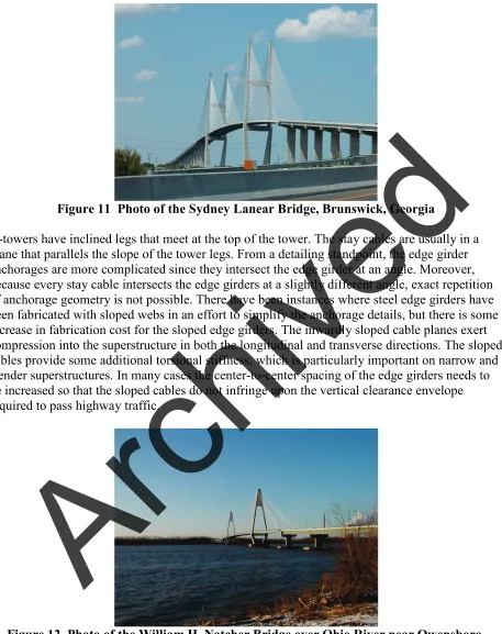
Figure 11 Photo of the Sydney Lanear Bridge, Brunswick, Georgia
A-towers have inclined legs that meet at the top of the tower. The stay cables are usually in a plane that parallels the slope of the tower legs. From a detailing standpoint, the edge girder anchorages are more complicated since they intersect the edge girder at an angle. Moreover, because every stay cable intersects the edge girders at a slightly different angle, exact repetition of anchorage geometry is not possible. There have been instances where steel edge girders have been fabricated with sloped webs in an effort to simplify the anchorage details, but there is some increase in fabrication cost for the sloped edge girders. The inwardly sloped cable planes exert compression into the superstructure in both the longitudinal and transverse directions. The sloped cables provide some additional torsional stiffness, which is particularly important on narrow and slender superstructures. In many cases the center-to-center spacing of the edge girders needs to be increased so that the sloped cables do not infringe upon the vertical clearance envelope required to pass highway traffic.
Figure 12 Photo of the William H. Natcher Bridge over Ohio River near Owensboro, Kentucky
Inverted Y-towers are a variation of the A-tower. In this case, the sloped tower legs meet well above the roadway and a vertical column extends upward from the intersection of the sloped
legs. The stay cables are then anchored in the vertical column. Every stay cable intersects the edge girders at a slightly different angle so that exact repetition of anchorage geometry is not possible. The advantages and disadvantages discussed for the cables are similar to those
discussed above regarding A-towers. Achieving the desired clearance envelope for traffic may be more critical for the inverted Y-towers, possibly requiring even further widening of the
superstructure since the inward cable slopes are more significant.
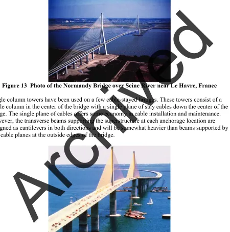
Figure 13 Photo of the Normandy Bridge over Seine River near Le Havre, France
Single column towers have been used on a few cable-stayed bridges. These towers consist of a single column in the center of the bridge with a single plane of stay cables down the center of the bridge. The single plane of cables offers some economy in cable installation and maintenance. However, the transverse beams supporting the superstructure at each anchorage location are designed as cantilevers in both directions and will be somewhat heavier than beams supported by two cable planes at the outside edges of the bridge.
Figure 14 Photo of the Sunshine Skyway Bridge, Tampa, Florida
Cable-stayed superstructures have taken many forms around the world. Concrete cable stays have used concrete edge girders with concrete decks (either precast or cast-in-place) as well as post-tensioned box girder sections. Steel and/or composite cable-stayed bridges have used either
18 I-shaped steel edge girders made composite with concrete decks. The edge girders carry bending between stay cable anchorages plus axial compression resulting from the horizontal component of the stay cable forces. The compressive forces are additive from the end of the longest cables toward the towers. In most cases the edge girder design is not controlled by bending but by the compressive forces imparted by the stay cables, requiring a heavier section in order to avoid buckling.
Various deck systems have been used for cable-stayed bridges. Cast-in-place concrete decks have been used, although they are not common. Precast concrete deck panels with specialized overlays are fairly common in current construction. When concrete decks are used it is common to provide longitudinal post-tensioning of the deck to prohibit cracking of the deck. The deck post-tensioning is generally heaviest far away from the towers. Compression from the anchorage forces spreads through the concrete near the towers and the need for post-tensioning diminishes. It is common to use specialized concrete overlays even for cast-in-place concrete decks
Orthotropic decks have also been used. However, in the U.S. the overall cost for orthotropic decks has limited their use to extremely long spans.
Modern stay cables consist of a cluster of parallel prestressing strands sized to carry the design load of the particular stay cable. The cables are housed in PVC pipes to protect them from the effects of weather. Early cable-stayed technology indicated that the cables should be grouted inside the pipe as an additional level of corrosion protection. Based on the performance of some of the early cable systems, the state of the art has moved away from grouting as a corrosion protection system.
2.6 Suspension Bridges
Suspension bridges are also suspended structures but use a different system. As with cable-stayed structures, suspension bridges rely on high-strength cables as major structural elements. Suspension bridges, whose towers are significantly shorter than those required for cable-stayed bridges, become economical for very long spans.
The most common form of suspension bridge uses an externally anchored suspender cable system. The main cables typically are located at the outside edges of the bridge and are draped over the towers where they rest in saddles. The ends of the main suspension cables are anchored either into large counterweights or directly into bedrock at the ends of the structure. Both the size of the cables and the magnitude of the tension in these main suspender cables determine the
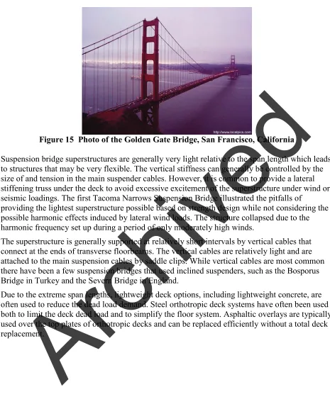
Figure 15 Photo of the Golden Gate Bridge, San Francisco, California
Suspension bridge superstructures are generally very light relative to the span length which leads to structures that may be very flexible. The vertical stiffness can generally be controlled by the size of and tension in the main suspender cables. However, it is common to provide a lateral stiffening truss under the deck to avoid excessive excitement of the superstructure under wind or seismic loadings. The first Tacoma Narrows Suspension Bridge illustrated the pitfalls of
providing the lightest superstructure possible based on strength design while not considering the possible harmonic effects induced by lateral wind loads. The structure collapsed due to the harmonic frequency set up during a period of only moderately high winds.
The superstructure is generally supported at relatively short intervals by vertical cables that connect at the ends of transverse floorbeams. The vertical cables are relatively light and are attached to the main suspension cables by saddle clips. While vertical cables are most common there have been a few suspension bridges that used inclined suspenders, such as the Bosporus Bridge in Turkey and the Severn Bridge in England.
Due to the extreme span lengths, lightweight deck options, including lightweight concrete, are often used to reduce the dead load demand. Steel orthotropic deck systems have often been used both to limit the deck dead load and to simplify the floor system. Asphaltic overlays are typically used over the top plates of orthotropic decks and can be replaced efficiently without a total deck replacement.
20
3.0 ECONOMICS
Welded plate girders are currently the most common type of steel bridge. Applicable in span lengths from approximately 90 feet to over 500 feet they provide a versatile choice for the designer. As the span lengths increase plate girders do not necessarily provide the lightest steel unit weight, but they often provide the most cost-effective design because the fabrication and erection costs are much lower than for trusses and arches.
Trusses are generally not cost-effective for span lengths under 450 feet. Below 450 feet the labor required to fabricate and erect a truss will generally exceed any additional material cost required for a deck girder design. The practical upper limit for simple span trusses is approximately 750 feet while continuous trusses begin to be cost-effective when the span length exceeds 550 feet. Continuous or cantilever trusses can span considerably longer distances than simple span trusses. The cost of truss spans increases rapidly as the span length exceeds 900 feet. In recent years, as cable-stayed bridges have become more common and the technology refined, very few trusses longer than 900 feet have been constructed in the United States.
Arches have been used for span lengths from approximately 200 feet up to 1800 feet worldwide. Arches used for the shorter span lengths, either with tied arches or true arches, are generally used more for aesthetics than effectiveness. Tied arches generally can be considered
cost-effective for span lengths from approximately 450 to 900 feet. Once the span approaches the 900 feet' range erection costs begin to climb significantly. True arches have been used for span lengths up to 1800 feet, such as the recently constructed Lupu Bridge in China. Solid rib arches are economical and attractive for shorter span lengths; however, once the span lengths approach approximately 1000 feet trussed arches often prove to be more cost-effective.
Cable-stayed bridges have been constructed with main span lengths less than 200 feet and extending up to nearly 3000 feet. In the U.S., cable-stayed bridges become very cost competitive for main span lengths over 750 feet. Almost all bridges with main span lengths in excess of 1000 feet built in the U.S. since 1980 have been cable-stayed structures. They are more versatile than suspension bridges in that they offer more possible configurations and towers can be constructed in less than optimal foundation conditions because having good rock near the surface is not a requirement.
Prior to 1970, it was generally considered that suspension bridges provided the most economical solution for span lengths in excess of about 1200 feet. With the development of cable-stayed bridge technology, suspension bridges do not become economical until the main span length approaches 3000 feet. The last major suspension bridge constructed in the U.S. was the second William Preston Lane, Jr. Bridge near Annapolis Maryland which was completed in 1973. This bridge was a twin to the original suspension bridge at the site. Suspension bridges require large expensive steel castings for the cable saddles on the main towers, at rocker bents, at the ends of the side spans and at splay bents and anchorages.
4.0 CONSTRUCTABILITY
4.1 Rolled Beams/Welded Plate Girders
Rolled beam and plate girder bridges are generally easily constructed, particularly for span lengths less than 200 feet, which encompasses a large majority of the steel bridges constructed in the U.S. For span lengths under 200 feet the girders can generally be erected with little or no falsework. Pier brackets are often used to provide stability of the negative moment sections until the positive moment sections can be erected. As the span lengths exceed 200 feet falsework towers may become necessary to erect the girders.
Stability of the girders during erection also becomes increasingly critical as the span lengths exceed 200 feet. Lateral bracing or additional falsework towers may be necessary to assure adequate lateral stiffness or to assure proper positioning of the girders for long span and/or curved girders.
To open up the bidding on projects to the largest number of fabricators possible, it is generally advisable to limit the length of field sections to a maximum length of 120 feet, although shipping pieces up to 160 feet have been used. Hauling permits become more expensive for longer
sections, especially for lengths greater than 140 feet, and in some cases the piece weight may become prohibitive. The piece weight also affects erection because heavier cranes may be required.
4.2 Trusses
When compared with deck girder structures, truss construction is a much more labor intensive process. There are more discrete members to erect including not only truss members but lateral bracing, sway bracing and floor system members. The weight and size of the members is usually lighter than those encountered in deck girder bridges. This allows the erector to use smaller cranes than might be needed for plate girders.
Truss bridges have more bolted field connections than are required for plate girder bridges. These require additional labor to erect which generally makes the erection time for trusses longer than for girder bridges.
Simple span trusses usually require falsework towers adjacent to both piers in order to facilitate erection. Dependent upon the span length, the falsework location and the panel length, it may also be necessary to provide counterweights near the end piers to assure static equilibrium prior to closure of the span.
Continuous trusses can often be erected using a balanced cantilever approach requiring falsework towers near the interior piers. This can be particularly important when crossing navigable
waterways where it is necessary to maintain a navigation channel at all times. While the falsework towers for a simple span truss by necessity are placed adjacent to the navigation channel, the towers for continuous trusses can usually be placed in spans adjacent to the navigation span. This often allows the towers to be lighter while minimizing the risk of the towers being struck by commercial traffic during truss erection.
22
4.3 Arches
Arches are more complex to erect than trusses or plate girders. The arch rib must have temporary support during erection, either by falsework towers under the rib or through a system of
backstays that support the ribs until they can be closed at the crown.
In many cases the piece weights that are used for arches are heavier than the pieces used for truss members and, in some cases, those used for plate girders as well. The erector also needs to exercise greater care during erection to assure the proper structure geometry than is generally required for girders or trusses.
Another concern may be the height of the arch. In order to have a span-to-rise ratio that provides an economical design, arches are generally higher (from the spring line to the crown) than would be a truss with a comparable span. The additional height, in conjunction with the heavier
member weights, can require significantly larger cranes than would be required to erect a truss.
When over water, some tied arches have been erected on barge-supported falsework, floated into position and then lowered onto the piers.
4.4 Cable-Stayed Bridges
Cable-stayed bridges are becoming more common worldwide. One significant reason for this is that the erection methods required for cable-stayed bridges have become better understood over the past 25 years.
The towers for cable-stayed bridges are very tall relative to the span length and in most cases consist of hollow concrete sections. The towers carry very high loads because of the long spans and must also resist significant bending. The foundations are often relatively large, which may lead to constructability issues when crossing rivers or other bodies of water.
Once the towers are completed, the cable-stayed superstructures can be constructed without falsework towers, which can provide significant benefits over navigable waterways. The
construction uses a balanced cantilever method proceeding away from the towers until the spans can be closed. The stay cable tensions may require adjustment through the construction process to assure the correct final forces and bridge geometry.
4.5 Suspension Bridges
Erection of suspension bridges is relatively specialized. The installation of the main suspender cables requires expertise that very few contractors possess. Maintaining the geometry of the main cables is critical. The cable saddles on top of the towers may need to be adjusted horizontally during erection to keep the resultant loads on the towers relatively vertical and to avoid
horizontal loads at the top of the towers. The tower design may need to be heavier to provide the capacity to resist these loads unless such adjustment is provided.
The time to construct a suspension bridge is often relatively long as well. The foundations for the towers and anchorages are elaborate and time-consuming.
There are also numerous pieces to erect due to the need to provide a stiffening truss to mitigate lateral movement of the bridge. In many cases, complete panels of the stiffening
truss/floorbeams are erected together. The longitudinal stringers and deck, or the orthotropic deck system, are generally installed later. As with the cable-stayed bridges, faslework is usually not necessary to facilitate superstructure erection.
24
5.0 REFERENCES
1. AASHTO, (2002). Standard Specifications for Highway Bridges, 17th Edition, AASHTO, Washington D.C.
2. AASHTO, (2010). AASHTO LRFD Bridge Design Specifications; 5th Edition, AASHTO, Washington D.C.