O
perating
S
yStemS
I
nternals
and
d
esIgn
P
rIncIPles
n
inth
e
ditiOn
g
lObal
e
ditiOn
Director, Portfolio Management: Engineering, Computer Science & Global Editions: Julian Partridge Higher Ed Portfolio Management: Tracy Johnson
(Dunkelberger)
Acquisitions Editor, Global Editions: Sourabh Maheshwari Portfolio Management Assistant: Kristy Alaura
Managing Content Producer: Scott Disanno Content Producer: Robert Engelhardt
Project Editor, Global Editions: K.K. Neelakantan Web Developer: Steve Wright
Rights and Permissions Manager: Ben Ferrini Manufacturing Buyer, Higher Ed, Lake Side
Communications Inc (LSC): Maura Zaldivar-Garcia
Media Production Manager, Global Editions: Vikram Kumar
Inventory Manager: Ann Lam Marketing Manager: Demetrius Hall Product Marketing Manager: Yvonne Vannatta Marketing Assistant: Jon Bryant
Cover Designer: Lumina Datamatics Cover Art: Shai_Halud/Shutterstock
Full-Service Project Management: Bhanuprakash Sherla, SPi Global
Credits and acknowledgments borrowed from other sources and reproduced, with permission, in this textbook appear on page CL-1.
Many of the designations by manufacturers and seller to distinguish their products are claimed as trademarks. Where those designations appear in this book, and the publisher was aware of a trademark claim, the designations have been printed in initial caps or all caps.
Pearson Education Limited Edinburgh Gate
Harlow Essex CM20 2JE England
and Associated Companies throughout the world Visit us on the World Wide Web at:
www.pearsonglobaleditions.com
© Pearson Education Limited 2018
The right of William Stallings to be identified as the author of this work has been asserted by him in accordance with the Copyright, Designs and Patents Act 1988.
Authorized adaptation from the United States edition, entitled Operating Systems: Internals and Design Principles, 9th Edition, ISBN 978-0-13-467095-9, by William Stallings published by Pearson Education © 2018.
All rights reserved. No part of this publication may be reproduced, stored in a retrieval system, or transmitted in any form or by any means, electronic, mechanical, photocopying, recording or otherwise, without either the prior written permission of the publisher or a license permitting restricted copying in the United Kingdom issued by the Copyright Licensing Agency Ltd, Saffron House, 6–10 Kirby Street, London EC1N 8TS.
All trademarks used herein are the property of their respective owners. The use of any trademark in this text does not vest in the author or publisher any trademark ownership rights in such trademarks, nor does the use of such trademarks imply any affiliation with or endorsement of this book by such owners.
British Library Cataloguing-in-Publication Data
A catalogue record for this book is available from the British Library 10 9 8 7 6 5 4 3 2 1
C
OntentS
Online Chapters and Appendices 13 VideoNotes 15
Preface 17
About the Author 27
PART 1 BAckgRound 29
Chapter 1 Computer System Overview 29 1.1 Basic Elements 30
1.2 Evolution of the Microprocessor 32
1.3 Instruction Execution 32
1.4 Interrupts 35
1.5 The Memory Hierarchy 46
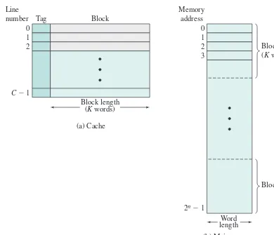
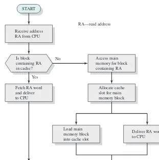
1.6 Cache Memory 49
1.7 Direct Memory Access 53
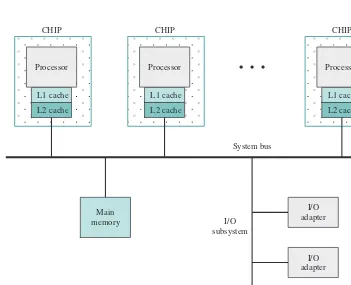
1.8 Multiprocessor and Multicore Organization 54
1.9 Key Terms, Review Questions, and Problems 58
1A Performance Characteristics of Two-Level Memories 61
Chapter 2 Operating System Overview 68
2.1 Operating System Objectives and Functions 69
2.2 The Evolution of Operating Systems 73
2.3 Major Achievements 83
2.4 Developments Leading to Modern Operating Systems 92
2.5 Fault Tolerance 95
2.6 OS Design Considerations for Multiprocessor and Multicore 98 2.7 Microsoft Windows Overview 101
2.8 Traditional UNIx Systems 108 2.9 Modern UNIx Systems 110 2.10 Linux 113
2.11 Android 118
2.12 Key Terms, Review Questions, and Problems 127
PART 2 PRocesses 129
Chapter 3 Process Description and Control 129 3.1 What is a Process? 131
3.2 Process States 133
3.3 Process Description 148
3.4 Process Control 157
3.5 Execution of the Operating System 163 3.6 UNIx SVR4 Process Management 166 3.7 Summary 171
3.8 Key Terms, Review Questions, and Problems 171
Chapter 4 Threads 176
4.1 Processes and Threads 177
4.2 Types of Threads 183
4.3 Multicore and Multithreading 190
4.4 Windows Process and Thread Management 195 4.5 Solaris Thread and SMP Management 202 4.6 Linux Process and Thread Management 206 4.7 Android Process and Thread Management 211 4.8 Mac OS x Grand Central Dispatch 215 4.9 Summary 217
4.10 Key Terms, Review Questions, and Problems 218
Chapter 5 Concurrency: Mutual Exclusion and Synchronization 223
5.1 Mutual Exclusion: Software Approaches 226
5.2 Principles of Concurrency 232
5.3 Mutual Exclusion: Hardware Support 241
5.4 Semaphores 244
5.5 Monitors 257
5.6 Message Passing 263
5.7 Readers/Writers Problem 270
5.8 Summary 274
5.9 Key Terms, Review Questions, and Problems 275
Chapter 6 Concurrency: Deadlock and Starvation 289 6.1 Principles of Deadlock 290
6.2 Deadlock Prevention 299
6.3 Deadlock Avoidance 300
6.4 Deadlock Detection 306
6.5 An Integrated Deadlock Strategy 308
6.6 Dining Philosophers Problem 309 6.7 UNIx Concurrency Mechanisms 313 6.8 Linux Kernel Concurrency Mechanisms 315 6.9 Solaris Thread Synchronization Primitives 324 6.10 Windows Concurrency Mechanisms 326 6.11 Android Interprocess Communication 330 6.12 Summary 331
PART 3 MeMoRy 339
Chapter 7 Memory Management 339
7.1 Memory Management Requirements 340
7.2 Memory Partitioning 344
7.3 Paging 355
7.4 Segmentation 358
7.5 Summary 360
7.6 Key Terms, Review Questions, and Problems 360
7A Loading and Linking 363
Chapter 8 Virtual Memory 370
8.1 Hardware and Control Structures 371
8.2 Operating System Software 388
8.3 UNIx and Solaris Memory Management 407 8.4 Linux Memory Management 413
8.5 Windows Memory Management 417 8.6 Android Memory Management 419 8.7 Summary 420
8.8 Key Terms, Review Questions, and Problems 421 PART 4 scheduling 425
Chapter 9 Uniprocessor Scheduling 425 9.1 Types of Processor Scheduling 426
9.2 Scheduling Algorithms 430 9.3 Traditional UNIx Scheduling 452 9.4 Summary 454
9.5 Key Terms, Review Questions, and Problems 455
Chapter 10 Multiprocessor, Multicore, and Real-Time Scheduling 460 10.1 Multiprocessor and Multicore Scheduling 461
10.2 Real-Time Scheduling 474 10.3 Linux Scheduling 489 10.4 UNIx SVR4 Scheduling 492 10.5 UNIx FreeBSD Scheduling 494 10.6 Windows Scheduling 498 10.7 Summary 500
10.8 Key Terms, Review Questions, and Problems 500 PART 5 inPuT/ouTPuT And Files 505
Chapter 11 I/O Management and Disk Scheduling 505 11.1 I/O Devices 506
11.2 Organization of the I/O Function 508
11.4 I/O Buffering 514
11.5 Disk Scheduling 517
11.6 RAID 524
11.7 Disk Cache 533 11.8 UNIx SVR4 I/O 537 11.9 Linux I/O 540 11.10 Windows I/O 544 11.11 Summary 546
11.12 Key Terms, Review Questions, and Problems 547
Chapter 12 File Management 550 12.1 Overview 551
12.2 File Organization and Access 557
12.3 B-Trees 561
12.4 File Directories 564
12.5 File Sharing 569
12.6 Record Blocking 570
12.7 Secondary Storage Management 572 12.8 UNIx File Management 580 12.9 Linux Virtual File System 585 12.10 Windows File System 589 12.11 Android File Management 594 12.12 Summary 595
12.13 Key Terms, Review Questions, and Problems 596 PART 6 eMBedded sysTeMs 599
Chapter 13 Embedded Operating Systems 599 13.1 Embedded Systems 600
13.2 Characteristics of Embedded Operating Systems 605
13.3 Embedded Linux 609
13.4 TinyOS 615
13.5 Key Terms, Review Questions, and Problems 625
Chapter 14 Virtual Machines 627 14.1 Virtual Machine Concepts 628
14.2 Hypervisors 631
14.3 Container Virtualization 635
14.4 Processor Issues 642
14.5 Memory Management 644
14.6 I/O Management 645
14.7 VMware ESxi 647
14.8 Microsoft Hyper-V and xen Variants 650
14.9 Java VM 651
14.10 Linux Vserver Virtual Machine Architecture 652
14.11 Summary 655
Chapter 15 Operating System Security 657 15.1 Intruders and Malicious Software 658
15.2 Buffer Overflow 662
15.3 Access Control 670 15.4 UNIx Access Control 678 15.5 Operating Systems Hardening 681
15.6 Security Maintenance 685 15.7 Windows Security 686 15.8 Summary 691
15.9 Key Terms, Review Questions, and Problems 692
Chapter 16 Cloud and IoT Operating Systems 695 16.1 Cloud Computing 696
16.2 Cloud Operating Systems 704
16.3 The Internet of Things 720
16.4 IoT Operating Systems 724
16.5 Key Terms and Review Questions 731 APPendices
Appendix A Topics in Concurrency A-1 A.1 Race Conditions and Semaphores A-2
A.2 A Barbershop Problem A-9
A.3 Problems A-14
Appendix B Programming and Operating System Projects B-1 B.1 Semaphore Projects B-2
B.2 File Systems Project B-3
B.3 OS/161 B-3
B.4 Simulations B-4
B.5 Programming Projects B-4
B.6 Research Projects B-6
B.7 Reading/Report Assignments B-7
B.8 Writing Assignments B-7
B.9 Discussion Topics B-7
B.10 BACI B-7
References R-1
Credits CL-1
O
nline
C
hapterS
and
a
ppendiCeS
1
13
1Online chapters, appendices, and other documents are Premium Content, available via the access card at the front of this book.Chapter 17 Network Protocols
17.1 The Need for a Protocol Architecture 17-3
17.2 The TCP/IP Protocol Architecture 17-5
17.3 Sockets 17-12
17.4 Linux Networking 17-16 17.5 Summary 17-18
17.6 Key Terms, Review Questions, and Problems 17-18
17A The Trivial File Transfer Protocol 17-21
Chapter 18 Distributed Processing, Client/Server, and Clusters 18.1 Client/Server Computing 18-2
18.2 Distributed Message Passing 18-12
18.3 Remote Procedure Calls 18-16
18.4 Clusters 18-19
18.5 Windows Cluster Server 18-25
18.6 Beowulf and Linux Clusters 18-27
18.7 Summary 18-29
18.8 References 18-29
18.9 Key Terms, Review Questions, and Problems 18-30
Chapter 19 Distributed Process Management 19.1 Process Migration 19-2
19.2 Distributed Global States 19-9
19.3 Distributed Mutual Exclusion 19-14
19.4 Distributed Deadlock 19-23
19.5 Summary 19-35
19.6 References 19-35
19.7 Key Terms, Review Questions, and Problems 19-37
Chapter 20 Overview of Probability and Stochastic Processes 20.1 Probability 20-2
20.2 Random Variables 20-7
20.3 Elementary Concepts of Stochastic Processes 20-12
20.4 Problems 20-20
Chapter 21 Queueing Analysis
21.1 How Queues Behave—A Simple Example 21-3
21.3 Queueing Models 21-10
21.4 Single-Server Queues 21-17
21.5 Multiserver Queues 21-20
21.6 Examples 21-20
21.7 Queues With Priorities 21-26
21.8 Networks of Queues 21-27
21.9 Other Queueing Models 21-31
21.10 Estimating Model Parameters 21-32
21.11 References 21-35
21.12 Problems 21-35
Programming Project One Developing a Shell
Programming Project Two The HOST Dispatcher Shell
Appendix C Topics in Concurrency C-1
Appendix D Object-Oriented Design D-1
Appendix E Amdahl’s Law E-1
Appendix F Hash Tables F-1
Appendix G Response Time G-1
Appendix H Queueing System Concepts H-1
Appendix I The Complexity of Algorithms I-1
Appendix J Disk Storage Devices J-1
Appendix K Cryptographic Algorithms K-1
Appendix L Standards Organizations L-1
Appendix M Sockets: A Programmer’s Introduction M-1
Appendix N The International Reference Alphabet N-1
Appendix O BACI: The Ben-Ari Concurrent Programming System O-1
Appendix P Procedure Control P-1
Appendix Q ECOS Q-1
V
ideO
n
OteS
Locations of VideoNotes
http://www.pearsonglobaleditions.com/stallings
Chapter 5 Concurrency: Mutual Exclusion and Synchronization 223 5.1 Mutual Exclusion Attempts 227
5.2 Dekker’s Algorithm 230
5.3 Peterson’s Algorithm for Two Processes 231
5.4 Illustration of Mutual Exclusion 238
5.5 Hardware Support for Mutual Exclusion 242
5.6 A Definition of Semaphore Primitives 246
5.7 A Definition of Binary Semaphore Primitives 247
5.9 Mutual Exclusion Using Semaphores 249
5.12 An Incorrect Solution to the Infinite-Buffer Producer/Consumer Problem Using Binary Semaphores 252
5.13 A Correct Solution to the Infinite-Buffer Producer/Consumer Problem Using Binary Semaphores 254
5.14 A Solution to the Infinite-Buffer Producer/Consumer Problem Using Semaphores 255
5.16 A Solution to the Bounded-Buffer Producer/Consumer Problem Using Semaphores 256
5.17 Two Possible Implementations of Semaphores 257
5.19 A Solution to the Bounded-Buffer Producer/Consumer Problem Using a Monitor 260
5.20 Bounded-Buffer Monitor Code for Mesa Monitor 262
5.23 Mutual Exclusion Using Messages 268
5.24 A Solution to the Bounded-Buffer Producer/Consumer Problem Using Messages 269
5.25 A Solution to the Readers/Writers Problem Using Semaphore: Readers Have Priority 271
5.26 A Solution to the Readers/Writers Problem Using Semaphore: Writers Have Priority 273
5.27 A Solution to the Readers/Writers Problem Using Message Passing 274
5.28 An Application of Coroutines 277
Chapter 6 Concurrency: Deadlock and Starvation 289 6.9 Deadlock Avoidance Logic 305
6.12 A First Solution to the Dining Philosophers Problem 311
6.13 A Second Solution to the Dining Philosophers Problem 311
6.14 A Solution to the Dining Philosophers Problem Using a Monitor 312
6.18 Another Solution to the Dining Philosophers Problem Using a Monitor 337
Chapter 13 Embedded Operating Systems 599 13.12 Condition Variable Example Code 626 VideoNote
p
refaCe
WhAT’s neW in The ninTh ediTion
Since the eighth edition of this book was published, the field of operating systems has seen continuous innovations and improvements. In this new edition, I have tried to capture these changes while maintaining a comprehensive coverage of the entire field. To begin the process of revision, the eighth edition of this book was extensively reviewed by a number of professors who teach the subject and by professionals working in the field. The result is that, in many places, the narrative has been clari-fied and tightened, and illustrations have been improved.
Beyond these refinements to improve pedagogy and user friendliness, the technical content of the book has been updated throughout to reflect the ongo-ing changes in this excitongo-ing field, and the instructor and student support has been expanded. The most noteworthy changes are as follows:
• Updated Linux coverage: The Linux material has been updated and expanded to reflect changes in the Linux kernel since the eighth edition.
• Updated Android coverage: The Android material has been updated and expanded to reflect changes in the Android kernel since the eighth edition.
• New Virtualization coverage: The chapter on virtual machines has been com-pletely rewritten to provide better organization and an expanded and more up-to-date treatment. In addition, a new section has been added on the use of containers.
• New Cloud operating systems: New to this edition is the coverage of cloud operating systems, including an overview of cloud computing, a discussion of the principles and requirements for a cloud operating system, and a discussion of a OpenStack, a popular open-source Cloud OS.
• New IoT operating systems: New to this edition is the coverage of operating systems for the Internet of Things. The coverage includes an overview of the IoT, a discussion of the principles and requirements for an IoT operating sys-tem, and a discussion of a RIOT, a popular open-source IoT OS.
• Updated and Expanded Embedded operating systems: This chapter has been substantially revised and expanded including:
— The section on embedded systems has been expanded and now includes discussions of microcontrollers and deeply embedded systems.
— The overview section on embedded OSs has been expanded and updated.
— The treatment of embedded Linux has been expanded, and a new discussion of a popular embedded Linux system, mClinux, has been added.
• Concurrency: New projects have been added to the Projects Manual to better help the student understand the principles of concurrency.
oBJecTiVes
This book is about the concepts, structure, and mechanisms of operating systems. Its purpose is to present, as clearly and completely as possible, the nature and charac-teristics of modern-day operating systems.
This task is challenging for several reasons. First, there is a tremendous range and variety of computer systems for which operating systems are designed. These include embedded systems, smart phones, single-user workstations and personal computers, medium-sized shared systems, large mainframe and supercomputers, and specialized machines such as real-time systems. The variety is not just con-fined to the capacity and speed of machines, but in applications and system support requirements. Second, the rapid pace of change that has always characterized com-puter systems continues without respite. A number of key areas in operating system design are of recent origin, and research into these and other new areas continues.
In spite of this variety and pace of change, certain fundamental concepts apply consistently throughout. To be sure, the application of these concepts depends on the current state of technology and the particular application requirements. The in-tent of this book is to provide a thorough discussion of the fundamentals of operat-ing system design, and to relate these to contemporary design issues and to current directions in the development of operating systems.
eXAMPle sysTeMs
This text is intended to acquaint the reader with the design principles and imple-mentation issues of contemporary operating systems. Accordingly, a purely concep-tual or theoretical treatment would be inadequate. To illustrate the concepts and to tie them to real-world design choices that must be made, four operating systems have been chosen as running examples:
• Windows: A multitasking operating system for personal computers, worksta-tions, servers, and mobile devices. This operating system incorporates many of the latest developments in operating system technology. In addition, Windows is one of the first important commercial operating systems to rely heavily on object-oriented design principles. This book covers the technology used in the most recent version of Windows, known as Windows 10.
• Android: Android is tailored for embedded devices, especially mobile phones. Focusing on the unique requirements of the embedded environment, the book provides details of Android internals.
• UNIX: A multiuser operating system, originally intended for minicomputers, but implemented on a wide range of machines from powerful microcomput-ers to supercomputmicrocomput-ers. Several flavors of UNIX are included as examples. FreeBSD is a widely used system that incorporates many state-of-the-art fea-tures. Solaris is a widely used commercial version of UNIX.
These systems were chosen because of their relevance and representativeness. The discussion of the example systems is distributed throughout the text rather than assembled as a single chapter or appendix. Thus, during the discussion of concur-rency, the concurrency mechanisms of each example system are described, and the motivation for the individual design choices is discussed. With this approach, the design concepts discussed in a given chapter are immediately reinforced with real-world examples. For convenience, all of the material for each of the example sys-tems is also available as an online document.
suPPoRT oF AcM/ieee coMPuTeR science cuRRiculA 2013
The book is intended for both an academic and a professional audience. As a textbook, it is intended as a one-semester or two-semester undergraduate course in operating systems for computer science, computer engineering, and electrical engineering majors. This edition is designed to support the recommendations of the current (December 2013) version of the ACM/IEEE Computer Science Curricula 2013 (CS2013). The CS2013 curriculum recommendation includes Operating Systems (OS) as one of the Knowledge Areas in the Computer Science Body of Knowledge. CS2013 divides all course work into three categories: Core-Tier 1 (all topics should be included in the cur-riculum), Core-Tier 2 (all or almost all topics should be included), and Elective (desir-able to provide breadth and depth). In the OS area, CS2013 includes two Tier 1 topics, four Tier 2 topics, and six Elective topics, each of which has a number of subtopics. This text covers all of the topics and subtopics listed by CS2013 in these three categories.
Table P.1 shows the support for the OS Knowledge Areas provided in this text-book. A detailed list of subtopics for each topic is available as the file CS2013-OS .pdf at box.com/OS9e.
PlAn oF The TeXT
The book is divided into six parts:
1. Background
2. Processes
3. Memory
4. Scheduling
5. Input/Output and files
6. Advanced topics (embedded OSs, virtual machines, OS security, and cloud and IoT operating systems)
insTRucToR suPPoRT MATeRiAls
The major goal of this text is to make it as effective a teaching tool as possible for this fundamental yet evolving subject. This goal is reflected both in the structure of the book and in the supporting material. The text is accompanied by the following supplementary material to aid the instructor:
• Solutions manual: Solutions to end-of-chapter Review Questions and Problems.
• Projects manual: Suggested project assignments for all of the project catego-ries listed in this Preface.
• PowerPoint slides: A set of slides covering all chapters, suitable for use in lecturing.
• PDF files: Reproductions of all figures and tables from the book.
• Test bank: A chapter-by-chapter set of questions with a separate file of answers. Table P.1 Coverage of CS2013 Operating Systems (OSs) Knowledge Area
Topic Coverage in Book
Overview of Operating Systems (Tier 1) Chapter 2: Operating System Overview
Operating System Principles (Tier 1) Chapter 1: Computer System Overview Chapter 2: Operating System Overview
Concurrency (Tier 2) Chapter 5: Mutual Exclusion and Synchronization Chapter 6: Deadlock and Starvation
Appendix A: Topics in Concurrency Chapter 18: Distributed Process Management
Scheduling and Dispatch (Tier 2) Chapter 9: Uniprocessor Scheduling Chapter 10: Multiprocessor and Real-Time Scheduling
Memory Management (Tier 2) Chapter 7: Memory Management Chapter 8: Virtual Memory
Security and Protection (Tier 2) Chapter 15: Operating System Security
Virtual Machines (Elective) Chapter 14: Virtual Machines
Device Management (Elective) Chapter 11: I/O Management and Disk Scheduling
File System (Elective) Chapter 12: File Management
Real Time and Embedded Systems (Elective) Chapter 10: Multiprocessor and Real-Time Scheduling
Chapter 13: Embedded Operating Systems Material on Android throughout the text
Fault Tolerance (Elective) Section 2.5: Fault Tolerance
• VideoNotes on concurrency: Professors perennially cite concurrency as per-haps the most difficult concept in the field of operating systems for students to grasp. The edition is accompanied by a number of VideoNotes lectures discuss-ing the various concurrency algorithms defined in the book. This icon appears next to each algorithm definition in the book to indicate that a VideoNote is available:
• Sample syllabuses: The text contains more material that can be conveniently covered in one semester. Accordingly, instructors are provided with several sample syllabuses that guide the use of the text within limited time. These samples are based on real-world experience by professors with the seventh edition.
All of these support materials are available at the Instructor Resource Center (IRC) for this textbook, which can be reached through the publisher’s website http:// www.pearsonglobaleditions.com/stallings. To gain access to the IRC, please contact your local Pearson sales representative.
PRoJecTs And oTheR sTudenT eXeRcises
For many instructors, an important component of an OS course is a project or set of projects by which the student gets hands-on experience to reinforce concepts from the text. This book has incorporated a projects component in the course as a result of an overwhelming support it received. In the online portion of the text, two major programming projects are defined. In addition, the instructor’s support materials available through Pearson not only includes guidance on how to assign and struc-ture the various projects, but also includes a set of user’s manuals for various project types plus specific assignments, all written especially for this book. Instructors can assign work in the following areas:
• OS/161 projects: Described later.
• Simulation projects: Described later.
• Semaphore projects: Designed to help students understand concurrency concepts, including race conditions, starvation, and deadlock.
• Kernel projects: The IRC includes complete instructor support for two dif-ferent sets of Linux kernel programming projects, as well as a set of kernel programming projects for Android.
• Programming projects: Described below.
• Research projects: A series of research assignments that instruct the student to research a particular topic on the Internet and write a report.
• Reading/report assignments: A list of papers that can be assigned for reading and writing a report, plus suggested assignment wording.
• Writing assignments: A list of writing assignments to facilitate learning the material.
• Discussion topics: These topics can be used in a classroom, chat room, or mes-sage board environment to explore certain areas in greater depth and to foster student collaboration.
In addition, information is provided on a software package known as BACI that serves as a framework for studying concurrency mechanisms.
This diverse set of projects and other student exercises enables the instructor to use the book as one component in a rich and varied learning experience and to tailor a course plan to meet the specific needs of the instructor and students. See Appendix B in this book for details.
os/161
This edition provides support for an active learning component based on OS/161. OS/161 is an educational operating system that is becoming increasingly rec-ognized as the preferred teaching platform for OS internals. It aims to strike a balance between giving students experience in working on a real operating sys-tem, and potentially overwhelming students with the complexity that exists in a full-fledged operating system, such as Linux. Compared to most deployed operating systems, OS/161 is quite small (approximately 20,000 lines of code and comments), and therefore it is much easier to develop an understanding of the entire code base.
The IRC includes:
1. A packaged set of html files that the instructor can upload to a course server for student access.
2. A getting-started manual to be distributed to students to help them begin using OS/161.
3. A set of exercises using OS/161, to be distributed to students.
4. Model solutions to each exercise for the instructor’s use.
5. All of this will be cross-referenced with appropriate sections in the book, so the student can read the textbook material then do the corresponding OS/161 project.
siMulATions
AniMATions
This edition also incorporates animations. Animations provide a powerful tool for understanding the complex mechanisms of a modern OS. A total of 53 animations are used to illustrate key functions and algorithms in OS design. The animations are used for Chapters 3, 5, 6, 7, 8, 9, and 11.
PRogRAMMing PRoJecTs
This edition provides support for programming projects. Two major programming projects, one to build a shell, or command line interpreter, and one to build a process dispatcher are described in the online portion of this textbook. The IRC provides further information and step-by-step exercises for developing the programs.
As an alternative, the instructor can assign a more extensive series of pro-jects that cover many of the principles in the book. The student is provided with detailed instructions for doing each of the projects. In addition, there is a set of homework problems, which involve questions related to each project for the student to answer.
Finally, the project manual provided at the IRC includes a series of program-ming projects that cover a broad range of topics and that can be implemented in any suitable language on any platform.
online docuMenTs And VideonoTes FoR sTudenTs
For this new edition, a substantial amount of original supporting material for stu-dents has been made available online, at two online locations. The book’s website, at http://www.pearsonglobaleditions.com/stallings (click on Student Resources
link), includes a list of relevant links organized by chapter and an errata sheet for the book.
Purchasing this textbook new also grants the reader twelve months of access to the Companion Website, which includes the following materials:
• Online chapters: To limit the size and cost of the book, 5 chapters of the book, covering security, are provided in PDF format. The chapters are listed in this book’s table of contents.
• Online appendices: There are numerous interesting topics that support mate-rial found in the text, but whose inclusion is not warranted in the printed text. A total of 15 online appendices cover these topics for the interested student. The appendices are listed in this book’s table of contents.
• Animations: Animations provide a powerful tool for understanding the com-plex mechanisms of a modern OS. A total of 53 animations are used to illus-trate key functions and algorithms in OS design. The animations are used for Chapters 3, 5, 6, 7, 8, 9, and 11.
• VideoNotes: VideoNotes are step-by-step video tutorials specifically designed to enhance the programming concepts presented in this textbook. The book is accompanied by a number of VideoNotes lectures discussing the various con-currency algorithms defined in the book.
To access the Premium Content site, click on the Companion website link at www.pearsonglobaleditions.com/stallings and enter the student access code found on the card in the front of the book.
AcknoWledgMenTs
I would like to thank the following for their contributions. Rami Rosen contributed most of the new material on Linux. Vineet Chadha made a major contribution to the new chapter on virtual machines. Durgadoss Ramanathan provided the new mate-rial on Android ART.
Through its multiple editions this book has benefited from review by hun-dreds of instructors and professionals, who generously spared their precious time and shared their expertise. Here I acknowledge those whose help contributed to this latest edition.
The following instructors reviewed all or a large part of the manuscript for this edition: Jiang Guo (California State University, Los Angeles), Euripides Montagne (University of Central Florida), Kihong Park (Purdue University), Mohammad Abdus Salam (Southern University and A&M College), Robert Marmorstein (Longwood University), Christopher Diaz (Seton Hill University), and Barbara Bracken (Wilkes University).
Thanks also to all those who provided detailed technical reviews of one or more chapters: Nischay Anikar, Adri Jovin, Ron Munitz, Fatih Eyup Nar, Atte Peltomaki, Durgadoss Ramanathan, Carlos Villavieja, Wei Wang, Serban Constantinescu and Chen Yang.
Andrew Peterson of the University of Toronto prepared the OS/161 supple-ments for the IRC. James Craig Burley authored and recorded the VideoNotes.
Adam Critchley (University of Texas at San Antonio) developed the simula-tion exercises. Matt Sparks (University of Illinois at Urbana-Champaign) adapted a set of programming problems for use with this textbook.
Lawrie Brown of the Australian Defence Force Academy produced the mate-rial on buffer overflow attacks. Ching-Kuang Shene (Michigan Tech University) provided the examples used in the section on race conditions and reviewed the section. Tracy Camp and Keith Hellman, both at the Colorado School of Mines, developed a new set of homework problems. In addition, Fernando Ariel Gont con-tributed a number of homework problems; he also provided detailed reviews of all of the chapters.
I would also like to thank Bill Bynum (College of William and Mary) and Tracy Camp (Colorado School of Mines) for contributing Appendix O; Steve Taylor (Worcester Polytechnic Institute) for contributing the programming projects and reading/report assignments in the instructor’s manual; and Professor Tan N. Nguyen (George Mason University) for contributing the research projects in the instruction manual. Ian G. Graham (Griffith University) contributed the two programming projects in the textbook. Oskars Rieksts (Kutztown University) generously allowed me to make use of his lecture notes, quizzes, and projects.
Finally, I thank the many people responsible for the publication of this book, all of whom did their usual excellent job. This includes the staff at Pearson, par-ticularly my editor Tracy Johnson, her assistant Kristy Alaura, program manager Carole Snyder, and project manager Bob Engelhardt. Thanks also to the marketing and sales staffs at Pearson, without whose efforts this book would not be in front of you.
AcknoWledgMenTs FoR The gloBAl ediTion
a
bOut
the
a
uthOr
Dr. William Stallings has authored 18 titles, and including the revised editions, over 40 books on computer security, computer networking, and computer architecture. His writings have appeared in numerous publications, including the Proceedings of the IEEE,ACM Computing Reviews and Cryptologia.
He has received the Best Computer Science textbook of the Year award 13 times from the Text and Academic Authors Association.
In over 30 years in the field, he has been a technical contributor, technical manager, and an executive with several high-technology firms. He has designed and implemented both TCP/IP-based and OSI-based protocol suites on a variety of computers and operating systems, ranging from microcomputers to mainframes. As a consultant, he has advised government agencies, computer and software ven-dors, and major users on the design, selection, and use of networking software and products.
He created and maintains the Computer Science Student Resource Site at ComputerScienceStudent.com. This site provides documents and links on a variety of subjects of general interest to computer science students (and professionals). He is a member of the editorial board of Cryptologia, a scholarly journal devoted to all aspects of cryptology.
Dr. Stallings holds a Ph.D. from M.I.T. in Computer Science and a B.S. from Notre Dame in electrical engineering.
29
1.1 Basic Elements
1.2 Evolution of the Microprocessor
1.3 Instruction Execution
1.4 Interrupts
Interrupts and the Instruction Cycle Interrupt Processing
Multiple Interrupts
1.5 The Memory Hierarchy
1.6 Cache Memory
Motivation Cache Principles Cache Design
1.7 Direct Memory Access
1.8 Multiprocessor and Multicore Organization Symmetric Multiprocessors
Multicore Computers
1.9 Key Terms, Review Questions, and Problems
APPENDIX 1A Performance Characteristics of Two-Level Memories
Locality
Operation of Two-Level Memory Performance
Computer system overview
Chapter
Background
An operating system (OS) exploits the hardware resources of one or more processors to provide a set of services to system users. The OS also manages secondary memory and I/O (input/output) devices on behalf of its users. Accordingly, it is important to have some understanding of the underlying computer system hardware before we begin our examination of operating systems.
This chapter provides an overview of computer system hardware. In most areas, the survey is brief, as it is assumed that the reader is familiar with this subject. How-ever, several areas are covered in some detail because of their importance to topics covered later in the book. Additional topics are covered in Appendix C. For a more detailed treatment, see [STAL16a].
1.1 BAsic eleMenTs
At a top level, a computer consists of processor, memory, and I/O components, with one or more modules of each type. These components are interconnected in some fashion to achieve the main function of the computer, which is to execute programs. Thus, there are four main structural elements:
• Processor: Controls the operation of the computer and performs its data pro-cessing functions. When there is only one processor, it is often referred to as the central processing unit (CPU).
• Main memory: Stores data and programs. This memory is typically volatile; that is, when the computer is shut down, the contents of the memory are lost. In contrast, the contents of disk memory are retained even when the computer system is shut down. Main memory is also referred to as real memory or primary memory.
l
EARNINGo
BJECTIVESAfter studying this chapter, you should be able to:
• Describe the basic elements of a computer system and their interrelationship.
• Explain the steps taken by a processor to execute an instruction.
• Understand the concept of interrupts, and how and why a processor uses interrupts.
• List and describe the levels of a typical computer memory hierarchy.
• Explain the basic characteristics of multiprocessor systems and multicore computers.
• Discuss the concept of locality and analyze the performance of a multilevel memory hierarchy.
• I/O modules: Move data between the computer and its external environment. The external environment consists of a variety of devices, including secondary memory devices (e.g., disks), communications equipment, and terminals.
• System bus: Provides for communication among processors, main memory, and I/O modules.
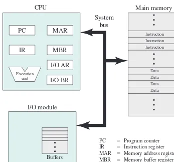
Figure 1.1 depicts these top-level components. One of the processor’s functions is to exchange data with memory. For this purpose, it typically makes use of two internal (to the processor) registers: a memory address register (MAR), which speci-fies the address in memory for the next read or write; and a memory buffer register (MBR), which contains the data to be written into memory, or receives the data read from memory. Similarly, an I/O address register (I/OAR) specifies a particular I/O device. An I/O buffer register (I/OBR) is used for the exchange of data between an I/O module and the processor.
A memory module consists of a set of locations, defined by sequentially num-bered addresses. Each location contains a bit pattern that can be interpreted as either
Figure 1.1 Computer Components: Top-Level View
CPU
Main memory
System
bus
I/O module
Buffers
Instruction
n22 n21 Data
Data Data Data Instruction Instruction
PC 5 Program counter IR 5 Instruction register MAR 5 Memory address register MBR 5 Memory buffer register I/O AR 5 Input/output address register I/O BR 5 Input/output buffer register
0 1 2
PC
MAR
IR
MBR
I/O AR
I/O BR
Executionan instruction or data. An I/O module transfers data from external devices to proces-sor and memory, and vice versa. It contains internal buffers for temporarily storing data until they can be sent on.
1.2 eVoluTion oF The MicRoPRocessoR
The hardware revolution that brought about desktop and handheld computing was the invention of the microprocessor, which contained a processor on a single chip. Though originally much slower than multichip processors, microprocessors have continually evolved to the point that they are now much faster for most computa-tions due to the physics involved in moving information around in sub-nanosecond timeframes.
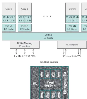
Not only have microprocessors become the fastest general-purpose processors available, they are now multiprocessors; each chip (called a socket) contains multiple processors (called cores), each with multiple levels of large memory caches, and mul-tiple logical processors sharing the execution units of each core. As of 2010, it is not unusual for even a laptop to have 2 or 4 cores, each with 2 hardware threads, for a total of 4 or 8 logical processors.
Although processors provide very good performance for most forms of com-puting, there is increasing demand for numerical computation. Graphical Processing Units (GPUs) provide efficient computation on arrays of data using Single- Instruction Multiple Data (SIMD) techniques pioneered in supercomputers. GPUs are no lon-ger used just for rendering advanced graphics, but they are also used for general numerical processing, such as physics simulations for games or computations on large spreadsheets. Simultaneously, the CPUs themselves are gaining the capability of operating on arrays of data–with increasingly powerful vector units integrated into the processor architecture of the x86 and AMD64 families.
Processors and GPUs are not the end of the computational story for the mod-ern PC. Digital Signal Processors (DSPs) are also present for dealing with stream-ing signals such as audio or video. DSPs used to be embedded in I/O devices, like modems, but they are now becoming first-class computational devices, especially in handhelds. Other specialized computational devices (fixed function units) co-exist with the CPU to support other standard computations, such as encoding/decoding speech and video (codecs), or providing support for encryption and security.
To satisfy the requirements of handheld devices, the classic microprocessor is giving way to the System on a Chip (SoC), where not just the CPUs and caches are on the same chip, but also many of the other components of the system, such as DSPs, GPUs, I/O devices (such as radios and codecs), and main memory.
1.3 insTRucTion eXecuTion
and instruction execution. Instruction execution may involve several operations and depends on the nature of the instruction.
The processing required for a single instruction is called an instruction cycle.
Using a simplified two-step description, the instruction cycle is depicted in Figure 1.2. The two steps are referred to as the fetch stage and the execute stage. Program execu-tion halts only if the processor is turned off, some sort of unrecoverable error occurs, or a program instruction that halts the processor is encountered.
At the beginning of each instruction cycle, the processor fetches an instruc-tion from memory. Typically, the program counter (PC) holds the address of the next instruction to be fetched. Unless instructed otherwise, the processor always increments the PC after each instruction fetch so it will fetch the next instruction in sequence (i.e., the instruction located at the next higher memory address). For example, consider a simplified computer in which each instruction occupies one 16-bit word of memory. Assume that the program counter is set to location 300. The proces-sor will next fetch the instruction at location 300. On succeeding instruction cycles, it will fetch instructions from locations 301, 302, 303, and so on. This sequence may be altered, as explained subsequently.
The fetched instruction is loaded into the instruction register (IR). The instruc-tion contains bits that specify the acinstruc-tion the processor is to take. The processor inter-prets the instruction and performs the required action. In general, these actions fall into four categories:
• Processor-memory: Data may be transferred from processor to memory, or from memory to processor.
• Processor-I/O: Data may be transferred to or from a peripheral device by trans-ferring between the processor and an I/O module.
• Data processing: The processor may perform some arithmetic or logic opera-tion on data.
• Control: An instruction may specify that the sequence of execution be altered. For example, the processor may fetch an instruction from location 149, which specifies that the next instruction be from location 182. The processor sets the program counter to 182. Thus, on the next fetch stage, the instruction will be fetched from location 182 rather than 150.
An instruction’s execution may involve a combination of these actions.
Consider a simple example using a hypothetical processor that includes the characteristics listed in Figure 1.3. The processor contains a single data register, called Figure 1.2 Basic Instruction Cycle
START Fetch next HALT
instruction
Fetch stage Execute stage
the accumulator (AC). Both instructions and data are 16 bits long, and memory is organized as a sequence of 16-bit words. The instruction format provides 4 bits for the opcode, allowing as many as 24 = 16 different opcodes (represented by a single hexadecimal1 digit). The opcode defines the operation the processor is to perform. With the remaining 12 bits of the instruction format, up to 212 = 4,096 (4K) words of memory (denoted by three hexadecimal digits) can be directly addressed.
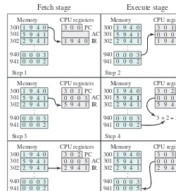
Figure 1.4 illustrates a partial program execution, showing the relevant portions of memory and processor registers. The program fragment shown adds the contents of the memory word at address 940 to the contents of the memory word at address 941 and stores the result in the latter location. Three instructions, which can be described as three fetch and three execute stages, are required:
1. The PC contains 300, the address of the first instruction. This instruction (the value 1940 in hexadecimal) is loaded into the IR and the PC is incremented. Note that this process involves the use of a memory address register (MAR) and a memory buffer register (MBR). For simplicity, these intermediate regis-ters are not shown.
2. The first 4 bits (first hexadecimal digit) in the IR indicate that the AC is to be loaded from memory. The remaining 12 bits (three hexadecimal digits) specify the address, which is 940.
3. The next instruction (5941) is fetched from location 301 and the PC is incremented.
1A basic refresher on number systems (decimal, binary, hexadecimal) can be found at the Computer Science Student Resource Site at ComputerScienceStudent.com.
Figure 1.3 Characteristics of a Hypothetical Machine
0 3 4 15
15
Opcode Address
0 1
S Magnitude
Program counter (PC) = Address of instruction Instruction register (IR) = Instruction being executed Accumulator (AC) = Temporary storage
(a) Instruction format
(b) Integer format
(c) Internal CPU registers
0001 = Load AC from memory 0010 = Store AC to memory 0101 = Add to AC from memory
4. The old contents of the AC and the contents of location 941 are added, and the result is stored in the AC.
5. The next instruction (2941) is fetched from location 302, and the PC is incremented.
6. The contents of the AC are stored in location 941.
In this example, three instruction cycles, each consisting of a fetch stage and an execute stage, are needed to add the contents of location 940 to the contents of 941. With a more complex set of instructions, fewer instruction cycles would be needed. Most modern processors include instructions that contain more than one address. Thus, the execution stage for a particular instruction may involve more than one reference to memory. Also, instead of memory references, an instruction may specify an I/O operation.
1.4 inTeRRuPTs
Virtually all computers provide a mechanism by which other modules (I/O, memory) may interrupt the normal sequencing of the processor. Table 1.1 lists the most com-mon classes of interrupts.
Figure 1.4 Example of Program Execution (contents of memory and registers in hexadecimal)
Interrupts are provided primarily as a way to improve processor utilization. For example, most I/O devices are much slower than the processor. Suppose that the processor is transferring data to a printer using the instruction cycle scheme of Figure 1.2. After each write operation, the processor must pause and remain idle until the printer catches up. The length of this pause may be on the order of many thousands or even millions of instruction cycles. Clearly, this is a very wasteful use of the processor.
To give a specific example, consider a PC that operates at 1 GHz, which would allow roughly 109 instructions per second.2 A typical hard disk has a rotational speed of 7200 revolutions per minute for a half-track rotation time of 4 ms, which is 4 mil-lion times slower than the processor.
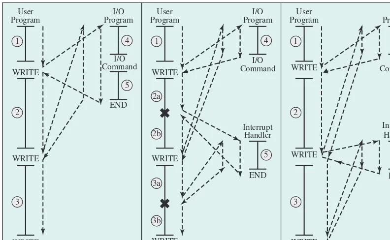
Figure 1.5a illustrates this state of affairs. The user program performs a series of WRITE calls interleaved with processing. The solid vertical lines represent seg-ments of code in a program. Code segseg-ments 1, 2, and 3 refer to sequences of instruc-tions that do not involve I/O. The WRITE calls are to an I/O routine that is a system utility and will perform the actual I/O operation. The I/O program consists of three sections:
• A sequence of instructions, labeled 4 in the figure, to prepare for the actual I/O operation. This may include copying the data to be output into a special buffer and preparing the parameters for a device command.
• The actual I/O command. Without the use of interrupts, once this command is issued, the program must wait for the I/O device to perform the requested func-tion (or periodically check the status of, or poll, the I/O device). The program might wait by simply repeatedly performing a test operation to determine if the I/O operation is done.
• A sequence of instructions, labeled 5 in the figure, to complete the opera-tion. This may include setting a flag indicating the success or failure of the operation.
The dashed line represents the path of execution followed by the processor; that is, this line shows the sequence in which instructions are executed. Thus, after the first
2A discussion of the uses of numerical prefixes, such as giga and tera, is contained in a supporting document at the Computer Science Student Resource Site at ComputerScienceStudent.com.
Program Generated by some condition that occurs as a result of an instruction execu-tion, such as arithmetic overflow, division by zero, attempt to execute an illegal machine instruction, or reference outside a user’s allowed memory space.
Timer Generated by a timer within the processor. This allows the operating system to perform certain functions on a regular basis.
I/O Generated by an I/O controller, to signal normal completion of an operation or to signal a variety of error conditions.
WRITE instruction is encountered, the user program is interrupted and execution continues with the I/O program. After the I/O program execution is complete, execu-tion resumes in the user program immediately following the WRITE instrucexecu-tion.
Because the I/O operation may take a relatively long time to complete, the I/O program is hung up waiting for the operation to complete; hence, the user program is stopped at the point of the WRITE call for some considerable period of time.
Interrupts and the Instruction Cycle
With interrupts, the processor can be engaged in executing other instructions while an I/O operation is in progress. Consider the flow of control in Figure 1.5b. As before, the user program reaches a point at which it makes a system call in the form of a WRITE call. The I/O program that is invoked in this case consists only of the prepa-ration code and the actual I/O command. After these few instructions have been executed, control returns to the user program. Meanwhile, the external device is busy accepting data from computer memory and printing it. This I/O operation is conducted concurrently with the execution of instructions in the user program.
When the external device becomes ready to be serviced (that is, when it is ready to accept more data from the processor) the I/O module for that external device sends an interrupt request signal to the processor. The processor responds by suspending operation of the current program; branching off to a routine to service Figure 1.5 Program Flow of Control Without and With Interrupts
User
(b) Interrupts; short I/O wait
User
(c) Interrupts; long I/O wait
that particular I/O device (known as an interrupt handler); and resuming the original execution after the device is serviced. The points at which such interrupts occur are indicated by in Figure 1.5b. Note that an interrupt can occur at any point in the main program, not just at one specific instruction.
For the user program, an interrupt suspends the normal sequence of execution. When the interrupt processing is completed, execution resumes (see Figure 1.6). Thus, the user program does not have to contain any special code to accommodate inter-rupts; the processor and the OS are responsible for suspending the user program, then resuming it at the same point.
To accommodate interrupts, an interrupt stage is added to the instruction cycle, as shown in Figure 1.7 (compare with Figure 1.2). In the interrupt stage, the proces-sor checks to see if any interrupts have occurred, indicated by the presence of an
Figure 1.6 Transfer of Control via Interrupts 1
2
i
i 1 1
M
Interrupt occurs here
User program Interrupt handler
Figure 1.7 Instruction Cycle with Interrupts
Fetch stage Execute stage Interrupt stage
START
HALT Interrupts
disabled
Interrupts enabled Fetch next
instruction
Execute instruction
Check for interrupt; initiate interrupt
interrupt signal. If no interrupts are pending, the processor proceeds to the fetch stage and fetches the next instruction of the current program. If an interrupt is pending, the processor suspends execution of the current program and executes an
interrupt-handler routine. The interrupt-handler routine is generally part of the OS. Typically, this routine determines the nature of the interrupt and performs whatever actions are needed. In the example we have been using, the handler determines which I/O module generated the interrupt, and may branch to a program that will write more data out to that I/O module. When the interrupt-handler routine is com-pleted, the processor can resume execution of the user program at the point of interruption.
It is clear that there is some overhead involved in this process. Extra instruc-tions must be executed (in the interrupt handler) to determine the nature of the interrupt and to decide on the appropriate action. Nevertheless, because of the relatively large amount of time that would be wasted by simply waiting on an I/O operation, the processor can be employed much more efficiently with the use of interrupts.
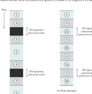
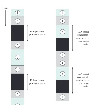
To appreciate the gain in efficiency, consider Figure 1.8, which is a timing dia-gram based on the flow of control in Figures 1.5a and 1.5b. Figures 1.5b and 1.8 assume
Figure 1.8 Program Timing: Short I/O Wait Time
4 1
5 5
2
5
3 4
I/O operation; processor waits
I/O operation concurrent with processor executing
I/O operation concurrent with processor executing I/O operation;
processor waits
4
2a 1
2b
4
3a
5
3b
(a) Without interrupts
that the time required for the I/O operation is relatively short: less than the time to complete the execution of instructions between write operations in the user program. The more typical case, especially for a slow device such as a printer, is that the I/O operation will take much more time than executing a sequence of user instructions. Figure 1.5c indicates this state of affairs. In this case, the user program reaches the second WRITE call before the I/O operation spawned by the first call is complete. The result is that the user program is hung up at that point. When the preceding I/O operation is completed, this new WRITE call may be processed, and a new I/O operation may be started. Figure 1.9 shows the timing for this situation with and without the use of interrupts. We can see there is still a gain in efficiency, because part of the time during which the I/O operation is underway overlaps with the execu-tion of user instrucexecu-tions.
Figure 1.9 Program Timing: Long I/O Wait 4
1
5
2
5
3 4 Time
4
2 1
5
4
(a) Without interrupts
(b) With interrupts 3
5 I/O operation;
processor waits
I/O operation; processor waits
I/O operation concurrent with processor executing;
then processor waits
I/O operation concurrent with processor executing;
Interrupt Processing
An interrupt triggers a number of events, both in the processor hardware and in software. Figure 1.10 shows a typical sequence. When an I/O device completes an I/O operation, the following sequence of hardware events occurs:
1. The device issues an interrupt signal to the processor.
2. The processor finishes execution of the current instruction before responding to the interrupt, as indicated in Figure 1.7.
3. The processor tests for a pending interrupt request, determines there is one, and sends an acknowledgment signal to the device that issued the interrupt. The acknowledgment allows the device to remove its interrupt signal.
4. The processor next needs to prepare to transfer control to the interrupt routine. To begin, it saves information needed to resume the current program at the point of interrupt. The minimum information required is the program status word3 (PSW) and the location of the next instruction to be executed, which is
3The PSW contains status information about the currently running process, including memory usage infor-mation, condition codes, and other status information such as an interrupt enable/disable bit and a kernel/ user-mode bit. See Appendix C for further discussion.
Figure 1.10 Simple Interrupt Processing Device controller or
other system hardware issues an interrupt
Processor finishes execution of current instruction
Processor signals acknowledgment of interrupt
Processor pushes PSW and PC onto control stack
Processor loads new PC value based on interrupt
Save remainder of process state information
Process interrupt
Restore process state information
Restore old PSW and PC
contained in the program counter (PC). These can be pushed onto a control stack (see Appendix P).
5. The processor then loads the program counter with the entry location of the interrupt-handling routine that will respond to this interrupt. Depending on the computer architecture and OS design, there may be a single program, one for each type of interrupt, or one for each device and each type of interrupt. If there is more than one interrupt-handling routine, the processor must deter-mine which one to invoke. This information may have been included in the original interrupt signal, or the processor may have to issue a request to the device that issued the interrupt to get a response that contains the needed information.
Once the program counter has been loaded, the processor proceeds to the next instruction cycle, which begins with an instruction fetch. Because the instruction fetch is determined by the contents of the program counter, control is transferred to the interrupt-handler program. The execution of this program results in the following operations:
6. At this point, the program counter and PSW relating to the interrupted program have been saved on the control stack. However, there is other information that is considered part of the state of the executing program. In particular, the con-tents of the processor registers need to be saved, because these registers may be used by the interrupt handler. So all of these values, plus any other state infor-mation, need to be saved. Typically, the interrupt handler will begin by saving the contents of all registers on the stack. Other state information that must be saved will be discussed in Chapter 3. Figure 1.11a shows a simple example. In this case, a user program is interrupted after the instruction at location N. The contents of all of the registers plus the address of the next instruction (N + 1), a total of M words, are pushed onto the control stack. The stack pointer is updated to point to the new top of stack, and the program counter is updated to point to the beginning of the interrupt service routine.
7. The interrupt handler may now proceed to process the interrupt. This includes an examination of status information relating to the I/O operation or other event that caused an interrupt. It may also involve sending additional com-mands or acknowledgments to the I/O device.
8. When interrupt processing is complete, the saved register values are retrieved from the stack and restored to the registers (see Figure 1.11b).
9. The final act is to restore the PSW and program counter values from the stack. As a result, the next instruction to be executed will be from the previously interrupted program.
Multiple Interrupts
So far, we have discussed the occurrence of a single interrupt. Suppose, however, that one or more interrupts can occur while an interrupt is being processed. For example, a program may be receiving data from a communications line, and printing results at the same time. The printer will generate an interrupt every time it completes a print operation. The communication line controller will generate an interrupt every time a unit of data arrives. The unit could either be a single character or a block, depending on the nature of the communications discipline. In any case, it is possible for a com-munications interrupt to occur while a printer interrupt is being processed.
Figure 1.11 Changes in Memory and Registers for an Interrupt Start
(a) Interrupt occurs after instruction at location N
Two approaches can be taken to dealing with multiple interrupts. The first is to disable interrupts while an interrupt is being processed. A disabled interrupt
simply means the processor ignores any new interrupt request signal. If an interrupt occurs during this time, it generally remains pending and will be checked by the processor after the processor has reenabled interrupts. Thus, if an interrupt occurs when a user program is executing, then interrupts are disabled immediately. After the interrupt-handler routine completes, interrupts are reenabled before resuming the user program, and the processor checks to see if additional interrupts have occurred. This approach is simple, as interrupts are handled in strict sequential order (see Figure 1.12a).
Figure 1.12 Transfer of Control with Multiple Interrupts User program
Interrupt handler X
Interrupt handler Y
(a) Sequential interrupt processing
(b) Nested interrupt processing User program
Interrupt handler X
The drawback to the preceding approach is that it does not take into account relative priority or time-critical needs. For example, when input arrives from the com-munications line, it may need to be absorbed rapidly to make room for more input. If the first batch of input has not been processed before the second batch arrives, data may be lost because the buffer on the I/O device may fill and overflow.
A second approach is to define priorities for interrupts and to allow an inter-rupt of higher priority to cause a lower-priority interinter-rupt handler to be interinter-rupted (see Figure 1.12b). As an example of this second approach, consider a system with three I/O devices: a printer, a disk, and a communications line, with increasing pri-orities of 2, 4, and 5, respectively. Figure 1.13 illustrates a possible sequence. A user program begins at t = 0. At t = 10, a printer interrupt occurs; user information
is placed on the control stack and execution continues at the printer interrupt service routine (ISR). While this routine is still executing, at t = 15 a
commu-nications interrupt occurs. Because the commucommu-nications line has higher priority than the printer, the interrupt request is honored. The printer ISR is interrupted, its state is pushed onto the stack, and execution continues at the communications ISR. While this routine is executing, a disk interrupt occurs (t = 20). Because
this interrupt is of lower priority, it is simply held, and the communications ISR runs to completion.
When the communications ISR is complete (t = 25), the previous processor
state is restored, which is the execution of the printer ISR. However, before even a single instruction in that routine can be executed, the processor honors the higher-priority disk interrupt and transfers control to the disk ISR. Only when that routine is complete (t = 35) is the printer ISR resumed. When that routine completes (t = 40),
control finally returns to the user program.
Figure 1.13 Example Time Sequence of Multiple Interrupts User program interrupt service routinePrinter interrupt service routineCommunication
Disk interrupt service routine t 5 10
t 5 40
t51 5
t 5 25
t 5
25