14 DES 2011
PT PERTAMINA (PERSERO)
Cathodic Protection
Cathodic Protection
Impressed Current
Impressed Current
Agustus 2013
Pelatihan Basic Electrical
CONFIDENTIAL AND PROPRIETARY
CATHODIC PROTECTION
Cathodic Protection adalah salah satu teknik yang
digunakan untuk mengontrol korosi pada
k
l
permukaan logam.
APA ITU KOROSI ???
• Korosi = karat = Kerusakan material dikarenakan reaksi
• Korosi = karat = Kerusakan material dikarenakan reaksi
dengan lingkungannya.
• Karat = Zat berwarna merah kecoklatan pada
permukaan besi / baja
permukaan besi / baja
.• Akibat : Adanya proses elektrokimia atau fenomena
elektrikal.
Kriteria terjadinya peristiwa
korosi akibat pengaruh
elektrikal :
elektrikal :
1. Anoda dan Katoda
2. Berada dalam media elektrolit
yang sama
yang sama
3. Hubungan listrik antara anoda
dan katoda
4
Adanya O
2PERTAMINA
PENDAPAT LAIN :
Korosi
:
- Akibat reaksi elektrokimia
Sebab
:
- Perbedaan potential pada permukaan besi/baja
KOMBINASI REAKSI “OKSIDASI” DAN “REDUKSI” = REAKSI ‘REDOKS’
dengan produk akhir yang disebut RUST atau KARAT Reaksi korosi lain yang terjadi adalah terbentuknya Fe2O3 (hematit) :
PERTAMINA 3Fe(OH)2 + 2OH¯ ----> Fe3O4 + 4 H2O
KERUGIAN AKIBAT KOROSI
Kerugian karena korosi pada banyak
instalasi besi baja yang “rusak”
•
Akibat Langsung
Kerugian di USA pada tahun 1975
Kerugian di USA pada tahun 1975
adalah US$ 70 billion atau 3 – 5%
d i GNP k
k
k
dari GNP karena kerusakan
material.
•
Akibat Tidak Langsung
* Kematian dan kecelakaan
* Kematian dan kecelakaan.
* Produksi yang berkurang.
* Plant shut down.
* Over design
Over design.
* Kontaminasi produk.
METODA PENCEGAHAN
KOROSI
Penyelidikan pencegahan korosi diantaranya oleh :
National Association of Corrosion Engineers (NACE)
Federation of Societies for Paint Technology
Federation of Societies for Paint Technology
Steel Structure Painting Council (SSPC)
Dll.
Metoda antara lain :
APA ITU CATHODIC PROTECTION ?
CATHODIC PROTECTION adalah :
Proses pencegahan karat / korosi yang
Proses pencegahan karat / korosi yang
memanfaatkan proses / peristiwa korosi
itu sendiri
itu sendiri.
CATHODIC PROTECTION didapat dengan 2 cara :
1. SACRIFICIAL ANODE SYSTEM
2
IMPRESSED CURRENT SYSTEM
CATHODIC PROTECTION
CATHODIC PROTECTION
SISTEM PERLINDUNGAN KATODIK
Cara bekerja :
Mengubah potensial permukaan besi / baja menjadi katoda
Arus proteksi luar yang menekan / menahan arus keluar
D
h k t d
Daerah katoda
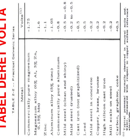
SACRIFICIAL SYSTEM
Mg
-1.50
PER
T
A
M
PRINCIPLES OF
CORROSION
Dimana 2 atau lebih metal yang terhubung
PRINCIPLES OF
CORROSION
Dimana 2 atau lebih metal yang terhubung Dimana 2 atau lebih metal yang terhubung
electrically, salah satu metal akan cenderung terkorosi terhadap metal lainnya.
Metal yang terletak di atas akan cenderung Dimana 2 atau lebih metal yang terhubung
electrically, salah satu metal akan cenderung terkorosi terhadap metal lainnya.
Metal yang terletak di atas akan cenderung Metal yang terletak di atas akan cenderung terkorosi dan akan melindungi metal di bawahnya.
Contoh:
Metal yang terletak di atas akan cenderung terkorosi dan akan melindungi metal di bawahnya.
Contoh:
Cooper dan Zinc terhubung satu sama lain, Zinc akan terkorosi sehingga akan memproteksi Copper.
Corrosion rate tergantung pada relative area Cooper dan Zinc terhubung satu sama lain,
Zinc akan terkorosi sehingga akan memproteksi Copper.
Corrosion rate tergantung pada relative area g g p antara anode dan cathode.
g g p antara anode dan cathode.
CONTOH PEMASANGAN SACRIFICIAL ANODE SYSTEM
Impressed Current Anodes
a)
Impressed current anodes must be able to pass d.c. current with
negligible metal loss
negligible metal loss
b)
Steel will lose 9kg per amp year.
c)
Impressed current anodes cause electrolysis of water and only a
few materials are suitable for this application.
2H
2O
4H
++ ½O
2 +
4e
d)
In sea water chlorine evolution will also take place
2Cl
- ½ Cl
Anodes
•
Platinised Titanium
a)
Inert Titanium substrate coated with 2.5, 5 or even 7.5 microns
of platinum.
b)
Can operate at high current densities in the range 100 to 5000
b)
Can operate at high current densities in the range 100 to 5000
Am
-2.
c)
Low consumption rate of 10 mg per amp per year.
c)
Low consumption rate of 10 mg per amp per year.
d)
Long Life if left energised, if not energised for 3 to 6 months
failure of the anode can occur.
e)
Limited operating voltages in seawater (12V)
f)
Need to be of robust construction when used on jetties
Other Anode Materials
•
Silicon Iron Chrome
▫
These are extremely brittle materials
▫
Operate at low current densities 10 to 40 Am 2
▫
Operate at low current densities 10 to 40 Am-2
▫
Consumption rate 0.2 to 0.5 kg A-1y-1
▫
Cheap and proven track record
•
Magnetite
▫
These are light and brittle
▫
Quite expensive
▫
Low consumption rate
▫
Relatively new anode material
L
d Sil
•
Lead Silver
▫
Only used in seawater
TYPES OF REFERENCE ELECTRODE
•
Copper/Copper Sulphate (Cu/CuSO
4) (For onshore
cathodic protection systems only)
•
Zinc
•
Silver/Silver Chloride/Seawater (Ag/AgCl)
Silver/Silver Chloride/Seawater (Ag/AgCl)
•
Specialist electrodes for cathodic protection in concrete
GROUNDBED
Effectivitas Cathodic Protection
Menurut NACE Standard :
Most commonly accepted criteria if
Effectivitas Cathodic Protection
Menurut NACE Standard :
Most commonly accepted criteria if
Most commonly accepted criteria if
a negative potential of at least
0.85 volt ( or More negative )
as measured between structure
Most commonly accepted criteria if
a negative potential of at least
0.85 volt ( or More negative )
as measured between structure
surface and saturated copper /
copper sulfate reference
electrode in contact with
electrolyte
surface and saturated copper /
copper sulfate reference
electrode in contact with
electrolyte
electrolyte
electrolyte
Effectivitas Cathodic Protection
Menurut BS 7361 Part 1 : Minimum protection criteria for Cathodic Protection.
• If the structure to seawater potential is more negative than -850mV vs a Cu/CuSOp g 44 electrode (or -800mV vs an Ag/AgCl) then full levels of cathodic protection are achieved in an aerobic environment.
• If the structure to seawater potential is more negative than -950mV vs a Cu/CuSOp g 44 electrode (-900 mV vs an Ag/AgCl electrode) then full levels of cathodic protection are achieved in an anaerobic environment.
• The maximum level of potential is determined by the structure coating CathodicThe maximum level of potential is determined by the structure coating Cathodic Disbondment of the coating can occur if a high negative potential is applied.
• The maximum negative potential is -1.10 to -1,15V vs Ag/AgCl. There is also the possibility of hydrogen embrittlement
T
ZONE OF CATHODIC PROTECTION
-0.9 -0.85 + 0.2
INCREASED OVERPROTECTION
PRODUCING BLISTERING OF PAINTS
-1.2
PRODUCING BLISTERING OF PAINTS
INCREASING DANGER OF
THE RELATIONSHIP BETWEEN THE
-1.4 EMBRITTLEMENT
-1.3 AND SPALLING
-0.3 -1.35
-0.2 -1.25
THE RELATIONSHIP BETWEEN THE CORROSION/CATHIODIC PROTECTION
Summary of Typical Maintenance Requirements Extracted
from BS 7361: Impressed Current CP Systems
Test Frequency: Test Description
Every 3 Months 1. At maximum intervals of 3 months check the satisfactory operation of transformers rectifiers.
satisfactory operation of transformers rectifiers.
Rectifier output voltages and currents should be recorded and pipe to soil potential recorded at the extremities of the pipeline and at test facilities midway
f f
between the transformer rectifier locations.
Test Frequency: Test Description
Every 12 Months 1. At maximum intervals of 12 months the pipe to soil potential should be recorded at all measuring locations and at other locations where a low potential has been recorded.
2. Potentials on secondary structures bonded into the CP system or with sacrificial anodes fitted should be recorded.
3 All transformer rectifiers and test facilities should be
PERTAMINA
Summary of Typical Maintenance Requirements Extracted
from BS 7361: Impressed Current CP Systems
Test Frequency: Test Description
Every 5 to 10 years 1. Close interval potential surveys should be conducted. These tests are primarily concerned with impressed current systems but should also be considered for sacrificial anode systems.
2. Repeat interference testing.
3 B di h k
3. Bonding checks.
Annual
▪
Carry out tests normally carried out at monthly and six monthly intervals.y y y y▪
Carry out Electrical Performance Tests on Transformer Rectifiers to comply with BS 7671.Specialist Checks Inspection Frequency to be agreed
Specialist Checks Inspection Frequency to be agreed
▪
Check condition of all reference electrode, anode and bonding cable connections from surface.▪
Check underwater condition of anodes/reference electrodes.C t t ti l f ll il t fi i t il b di
Aplication and Design :
Aplication and Design :
p
g
• Pipelines and Plants
• Heat Exchangers
p
g
• Pipelines and Plants
• Heat Exchangers
• Heat Exchangers
• Tanks
• Heat Exchangers
• Tanks
• Water Screens
• Marine Structures
• Water Screens
• Marine Structures
• Shipping
• Petro Chemical Plant
• Shipping
• Petro Chemical Plant
CONTOH APLIKASI CATHODIC PROTECTION
CONTOH APLIKASI CATHODIC PROTECTION
IMPRESSED CURRENT SYSTEM FOR PIPELINE
System : Impressed current using shallow ground bed
Material : Ferro Silicon Chromium (Fe/Si/Cr) Anode
IMPRESSED CURRENT SYSTEM FOR PIPELINE
System
: Impressed current semi deep well ground bed
System : Impressed current semi deep well ground bed
Material : Mixed Metal Oxide (MMO) Anode
SACRIFICIAL SYSTEM FOR PIPELINE
System
: Sacrificial
System : Sacrificial
Material : Magnesium Anode
IMPRESSED CURRENT SYSTEM FOR JETTY
System : Impressed current
M t i l
Pl ti i
d Tit
i
(Pt/Ti) A
d
Material : Platinised Titanium (Pt/Ti) Anode
IMPRESSED CURRENT SYSTEM FOR JETTY
System : Impressed current
Material
: Platinised Titanium (Pt/Ti) Anode
Material : Platinised Titanium (Pt/Ti) Anode
SACRIFICIAL SYSTEM FOR JETTY
System : Sacrificial
Material : Aluminium Anode
Rusted Structure : Jetty Splash Zone, Pipeline
Rusted Structure
SPLASH GUARD WRAPPING
SYSTEM FOR
JETTY
PER
T
A
M