Game
Programming
2
nd
Game
Programming
2
nd
Edition
Marketing Manager: Heather Hurley
Associate Marketing Manager:Kristin Eisenzopf Manager of Editorial Services:Heather Talbot Acquisitions Editor:Mitzi Foster-Koontz
Project Editor/Copy Editor:Cathleen D. Snyder Technical Reviewer: André LaMothe
Retail Market Coordinator: Sarah Dubois Interior Layout:Shawn Morningstar Cover Designer:Mike Tanamachi CD-ROM Producer:Brandon Penticuff Indexer: Katherine Stimson
Proofreader: Lorraine Gunter
DirectDraw, DirectMusic, DirectPlay, DirectSound, DirectX, Microsoft, Visual Basic, Visual C++, Windows, Windows NT, Xbox, and/or other Microsoft products are registered trademarks or trade-marks of Microsoft Corporation in the U.S. and/or other countries. All other tradetrade-marks are the property of their respective owners.
Important:Premier Press cannot provide software support. Please contact the appropriate software manufacturer’s technical support line or Web site for assistance.
Premier Press and the author have attempted throughout this book to distinguish proprietary trade-marks from descriptive terms by following the capitalization style used by the manufacturer.
Information contained in this book has been obtained by Premier Press from sources believed to be reliable. However, because of the possibility of human or mechanical error by our sources, Premier Press, or others, the Publisher does not guarantee the accuracy, adequacy, or completeness of any information and is not responsible for any errors or omissions or the results obtained from use of such information. Readers should be particularly aware of the fact that the Internet is an ever-chang-ing entity. Some facts may have changed since this book went to press.
ISBN: 1-931841-39-x
Library of Congress Catalog Card Number: 2003101212 Printed in the United States of America
03 04 05 06 07 BH 10 9 8 7 6 5 4 3 2 1
Premier Press, a division of Course Technology 25 Thomson Place
daughter, Anna, for showing me the important things in life.
Part One
DirectX Graphics: Don’t Hurt Me . . . 1
Chapter 1
The History of Direct3D/DirectX Graphics . . . 3
Chapter 2
Overview of HAL and COM . . . 9
Chapter 3
Programming Conventions. . . 19
Chapter 4
3D Fundamentals, Gouraud Shading,
and Texture-Mapping Basics . . . 27
Chapter 5
The Basics . . . 37
Chapter 6
First Steps to Animation. . . 77
Part Two
Knee-Deep in DirectX
Graphics Programming . . . 123
Chapter 7
Texture-Mapping Fundamentals . . . 125
Chapter 8
Using Multiple Textures . . . 149
Part Three
Hard-Core DirectX
Graphics Programming . . . 175
Chapter 9
Shader Programming with the
High-Level Shader Language. . . 177
Part Four
Appendixes . . . 299
Appendix A
Windows Game Programming Foundation . . . 301
Appendix B
C++ Primer . . . 327
Appendix C
Mathematics Primer . . . 353
Appendix D
Creating a Texture with
D3DXCreateTextureFromFileEx(). . . 371
Appendix E
Game Programming Resources . . . 375
Appendix F
What’s on the CD . . . 377
Part One
DirectX Graphics: Don’t Hurt Me . . . 1
Chapter 1
The History of Direct3D/DirectX Graphics. . . 3
DirectX 2.0 . . . 4
DirectX 6/7 . . . 5
DirectX 8. . . 5
Point Sprites . . . 6
3D Textures . . . 6
Direct3DX Utility Library . . . 6
Vertex and Pixel Shaders . . . 6
DirectX 9. . . 7
Summary . . . 8
Chapter 2
Overview of HAL and COM . . . 9
Hardware Abstraction Layer . . . 10
Pluggable Software Devices. . . 13
Reference Rasterizer . . . 14
Controlling Devices . . . 14
COM . . . 15
Naming Conventions . . . 22
Debugging DirectX. . . 24
Return Codes . . . 25
Summary. . . 26
Chapter 4
3D Fundamentals, Gouraud Shading,
and Texture-Mapping Basics . . . 27
3D Fundamentals . . . 28
Understanding Vertices . . . 30
Working with Orientation . . . 31
Understanding Faces . . . 31
Understanding Polygons . . . 33
Understanding Normals. . . 33
Understanding Normals and Gouraud Shading . . . 33
Texture-Mapping Basics . . . 34
Summary. . . 36
Chapter 5
The Basics . . . 37
Compiling the Examples . . . 38
The DirectX Graphics Common Architecture . . . 40
The Basic Example . . . 41
The ConfirmDevice(), OneTimeSceneInit(), and InitDeviceObjects() Functions . . . 44
The RestoreDeviceObjects() Method . . . 45
The FrameMove() Function . . . 53
The InitDeviceObjects() Function . . . 62
The RestoreDeviceObjects() Function . . . 62
The Render() Function . . . 64
The InvalidateDeviceObjects() Function . . . 66
The DeleteDeviceObjects() Function . . . 67
The FinalCleanup() Function . . . 67
The Basic3 Example . . . 67
The Basic4 Example . . . 69
The Basic5 Example . . . 75
Summary. . . 76
Chapter 6
First Steps to Animation . . . 77
Understanding Transformations and Viewports. . . 78
The World Transformation . . . 79
The View Transformation . . . 103
The Projection Transformation. . . 110
Working with the Viewport . . . 112
Depth Buffering. . . 116
Additional Resources . . . 119
Summary. . . 119
Chapter 7
Texture-Mapping Fundamentals . . . 125
What Is the Point of Textures? . . . 126
Working with Texture Coordinates . . . 129
Using Texture-Addressing Modes . . . 131
Wrap Texture-Addressing Mode . . . 132
Mirror Texture-Addressing Mode. . . 133
Clamp Texture-Addressing Mode . . . 134
Border Color Texture-Addressing Mode . . . 135
Mirroronce Texture-Addressing Mode . . . 136
Texture Wrapping. . . 136
Texture Filtering and Anti-Aliasing . . . 138
Mipmaps . . . 139
Nearest-Point Sampling. . . 140
Linear Texture Filtering . . . 141
Anisotropic Filtering . . . 142
Anti-Aliasing . . . 143
Alpha Blending. . . 145
Summary. . . 147
Chapter 8
Using Multiple Textures . . . 149
Multipass Rendering . . . 150
Color Operations . . . 153
Dark Mapping . . . 154
Animating the Dark Map . . . 157
Blending a Texture with Material Diffuse Color . . . 158
Multitexturing Support . . . 168
Texture Management . . . 169
Additional Resources . . . 169
Summary. . . 170
Part Two Quiz . . . 170
Part Three
Hard-Core DirectX
Graphics Programming . . . 175
Chapter 9
Shader Programming with the High-Level Shader
Language . . . 177
What You Need to Jump into HLSL . . . 179
Vertex and Pixel Shader Tasks. . . 180
Common Lighting Formulas Implemented with HLSL . . . 181
Ambient Lighting . . . 181
Diffuse Lighting . . . 183
Specular Lighting . . . 186
Self-Shadowing Term . . . 191
Bump Mapping. . . 192
Point Lights . . . 194
Summary. . . 196
Chapter 10
More Advanced Shader Effects . . . 197
Working with Cube Maps . . . 198
Generating Cube Maps . . . 198
Working with Shadows . . . 211
Shadow Volumes . . . 212
Things to Consider When Using Shadow Volumes . . . 226
Summary. . . 226
Chapter 11
Working with Files . . . 227
3D File Formats . . . 228
The X File Format . . . 229
Header. . . 230
Mesh . . . 231
MeshMaterialList . . . 232
Normals. . . 235
Textures. . . 236
Transformation Matrices. . . 242
Animation . . . 246
Using X Files . . . 249
Extending X Files . . . 251
Additional Resources . . . 252
X File Format . . . 252
Skinned Meshes. . . 252
Summary. . . 252
Chapter 12
Using *.md3 Files . . . 253
Files of the Trade . . . 254
Animation.cfg. . . 258
The .skin File . . . 260
Loading and Animating an .md3 Model . . . 273
Further Improvements . . . 298
Additional Resources . . . 298
Summary. . . 298
Part Four
Appendixes . . . 299
Appendix A
Windows Game Programming Foundation . . . 301
How to Look through a Window. . . 302
How Windows 95/98/ME/NT/2000/XP Interacts with Your Game . . . 302
The Components of a Window . . . 303
A Window Skeleton . . . 303
Step 1: Define a Window Class . . . 307
Step 2: Register the Window Class . . . 311
Step 3: Create a Window of That Class . . . 311
Step 4: Display the Window . . . 314
Step 5: Create the Message Loop. . . 315
The Window Procedure . . . 318
A Window Skeleton Optimized for Games . . . 318
Windows Resources . . . 322
Appendix B
C++ Primer . . . 327
What Is Object-Oriented Programming? . . . 328
Abstraction . . . 329
Class Hierarchies and Inheritance . . . 339
Virtual Functions . . . 343
Polymorphism . . . 345
Inline Functions . . . 345
C++ Enhancements to C . . . 347
Additional Resources . . . 352
Appendix C
Mathematics Primer . . . 353
Points in 3D . . . 354
Vectors. . . 356
Bound Vector. . . 356
Free Vector . . . 357
Unit Vector . . . 364
Matrices . . . 364
Multiplication of a Matrix by a Vector . . . 366
Matrix Addition and Subtraction . . . 366
Matrix Multiplication . . . 366
Translation Matrix . . . 367
Scaling Matrix . . . 367
Rotation Matrices . . . 367
Summary. . . 369
Appendix F
What’s on the CD. . . 377
DirectX 9.0 SDK . . . 378
ATI RenderMonkey. . . 378
NVIDIA Cg Toolkit . . . 379
Flash Movies . . . 379
The first edition of Beginning Direct 3D Game Programmingwas such a great success that we thought we would follow it up with a new edition that covers slightly more advanced material, such as shader and vertex programming, and at the same time update the text for DirectX 9.0. This second edition still starts off slowly and explains the key elements of Direct3D programming, but it takes the material a little further and shows you how to create some more advanced effects based on shader programming with the new shader programming languages, such as Microsoft’s High-Level Shader Language (HLSL). Additionally, we thought we would throw in some new material on Quake 2and Quake 3file formats for ani-mated meshes.
If you’re looking for a beginner book on Direct3D and you don’t want to wade through a lot of general DirectX coverage or Windows programming, then this book is for you.
Sincerely,
André LaMothe
I started the night of January 11th and finished about three days later with only a few hours of sleep. With the new experience in my head, I decided to start computer game program-ming. My goal was to program a terrain engine like Comanche. My then-girlfriend—now my wife—looked a little bit confused when a young, recently-graduated lawyer told her that he was going to be a game programmer.
About two years later, after becoming a member of the Gamedev Forum on CompuServe and reading a few books on game programming by André La Mothe and a good article by Peter Freese on height-mapping engines, I got my own engine up and running under OS/2. I wrote a few articles on OpenGL and OS/2 game programming for German jour-nals, coauthored a German book, and started on Windows game programming.
In 1997, I wrote my first online tutorials on DirectX programming and published them on my own Web site. After communicating with John Munsch and the other administrators of http://www.gamedev.net, I decided to make my tutorials accessible through their Web site as well. In the summer of 1998, as a beta-tester of the DirectX 6.0 SDK, I decided to write the first tutorial on the Direct3D Immediate Mode framework. At that time I used http://www.netit.net as my URL. There was a mailing list with a lot of interested people, and I got a lot of e-mails with positive feedback.
It started to be really fun. In 1999 I fired up my new Web site, at http://www.direct3d.net (now http://www.direct3d.info), with the sole purpose of providing understandable and instructive tutorials on Direct3D programming.
This was also my goal in writing the first edition of the book—to help readers understand and learn DirectX Graphics programming. Now it’s been more than two years since I wrote the first edition of the book. Two years is a long time in the real-time graphics industry, and also in my private life.
shaders to several ongoing software projects. But let’s get back to business….
Nowadays, there are graphics cards like the ATI RADEON 9800 PRO and the NVIDIA GeForce FX which have a much higher performance rate than the cards of two years ago. Vertex and pixel shaders are an integral part of every upcoming game, and therefore they are an integral part of the game development process. This fact and a huge number of e-mails led me to rethink the didactical structure of the second edition of this book. First of all, many e-mails suggested that the explanation on how to install the development environ-ment and the DirectX SDK wasn’t detailed enough in the first edition. Furthermore, the new must-have features of vertex and pixel shaders add an additional level of complexity to the development of even the simplest 3D example program. Therefore, this edition of the book has an extended introduction to the preparation of a development system, and the first chapters stick to the fixed-function pipeline to reduce the level of detail. I explain vertex and pixel shader programming later, in Part Three. Unfortunately, Amir Geva was not able to contribute his chapters on physics and collision detection to this edition. If you are inter-ested in using his collision detection library (ColDet) with DirectX, I would suggest reading the first edition of the book or going to his Web site, at http://www.photoneffect.com. I wish you as much fun reading this book as I had writing it. Don’t stop sending me e-mails. As you know, many improvements and new features in the book were implemented with e-mails from you in mind…and getting e-mails is what will drive me to improve this book further in upcoming editions.
Wolf ([email protected])
What You’re Going to Learn
This book covers all of the elements necessary to create a Windows 95/98/Me/NT/2000/XP or short Windows-based Direct3D/DirectX Graphics game for the PC, including:
• 3D graphics and algorithms
• Game programming techniques and data structures • Using 3D files to construct game worlds
• Programming your own character engine with a character animation system • DirectX Graphics programming
primer in Appendix B, so check it out.
You aren’t taking a stab at graphics/game programming to learn the math. If you can add, subtract, multiply, divide, and maybe square a number, you will be able to understand 90 percent of the math and what’s going on in this book. There’s a math primer provided in Appendix C just to be absolutely sure that you won’t miss anything.
How This Book Is Organized
This book consists of four parts. The first part will show you the essentials of Direct3D game programming. It deals with the programming conventions, basic algorithms, texture-mapping basics, 3D math, transformation pipeline, lighting, and depth buffers.
In the second part, you will learn how to use the transformation and lighting pipeline to map textures onto objects with different effects. All of the buzzwords, such as bump mapping, environment mapping, and procedural textures, are explained, and the effects are shown in sample programs.
In the third part of this book, you’ll deal with file formats and how to integrate them into your game engine. The file formats used are the greatly enhanced .X file format, introduced with the DirectX 8.0 SDK, and the MD3 file format used in most of the games driven by the
9.0 SDK for C/C++, and the DirectX 9 Developer Runtime, which you need to install in order to compile and run the example programs discussed in the book. (See the installa-tion instrucinstalla-tions in the following secinstalla-tion.) The DirectX SDK contains the run-time files, headers, and libraries you need to compile the book examples, and it provides many example programs for every component of DirectX.
You will find the example code from the book in directories named after the chapters of the book. In every example directory, you’ll find the graphics and source files. There’s also a readme.txt file, which provides you with additional information on compiling the application.
You’ll need a system that fulfills the requirements of DirectX to run the example programs. The minimum requirements are
• Windows 2000 with at least Service Pack 2 or higher. (I recommend Windows XP Professional with the latest service pack because only the Professional version will let you install the Debug run-time you need to develop DirectX applications.) • Visual C/C++ 6.0 with at least Service Pack 5. (I recommend Visual C++ .NET
with the latest service pack.) • At least 256 MB of RAM.
• At least 600 MB of free hard drive storage space. (Usually a lot more is a better bet.) • A hardware-accelerated 3D graphics card. To get the maximum visual experience for
the examples, you need relatively new graphics hardware. The pixel shader examples will only run on DirectX 8.1-capable hardware. Some of the examples need a graph-ics card that is capable of supporting some features of DirectX 9 in hardware. • The newest graphics card device driver.
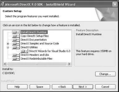
When you click on the file named dx90_sdk_devruntime.exe, the files will be decompressed into the selected temporary directory, shown in Figure I.2.
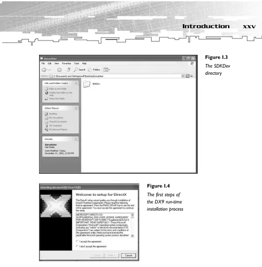
I chose a folder named dxruntime on the Desktop. After unzipping the files into the appro-priate folder, you will find within that folder another folder named SDKDev, as shown in Figure I.3.
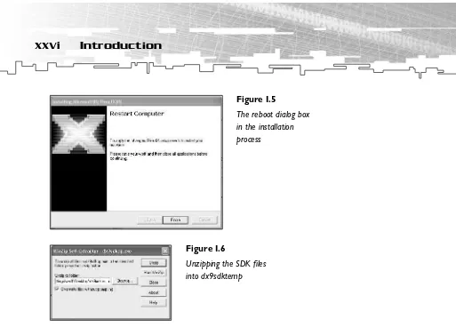
The SDKDev folder contains two folders named Debug and Retail. You should choose the Debug folder to get as much debug info as possible. The Retail builds are stripped of many debug checks and are also compiled to run faster. If you plan to simply play DirectX games and not write your own, the Retail builds are the best choice. The Debug builds help coders get their DirectX applications up and running. They help you track down bugs by giving you debug messages. The tradeoff, however, is that they run slower than the Retail builds. In the Debug folder, you will find a file named dxdevrtm.exe. When you click on this file, the installation process starts, as shown in Figure I.4.
You don’t get many choices from now on. All you have to do is accept the usual license agreement and start the process. At the end, you will be forced to reboot your computer after you click on Finish in the dialog box.
Figure I.1
The two necessary files to install DirectX 9
Figure I.2
After the reboot, it might be a good idea to delete the temporary dxruntime folder from the Desktop.
The next step to installing DirectX 9 on your computer is to install the SDK. Click on the second file with the name dx9sdkcp.exe. Again choose a temporary folder name. I suggest using the name dx9sdktemp on your Desktop, as shown in Figure I.6.
Figure I.4
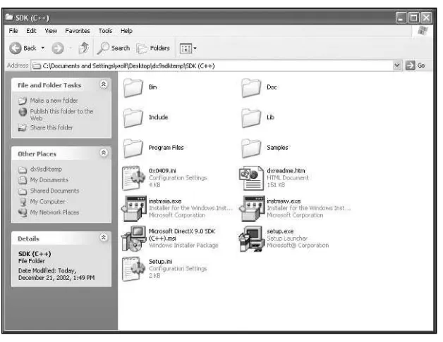
Then click on the folder in the temporary directory named SDK (C++), as shown in Figure 1.7.
Figure I.6
Unzipping the SDK files into dx9sdktemp
Figure I.7
Click on setup.exe to start the installation procedure. During the setup process, you have to accept the license agreement, and you can choose different components. I suggest using all components and specifying your directory (see Figure I.9). The default directory should be C:\DXSDK. Choosing this directory makes it easier to compile examples developed by others. After you complete the installation procedure by clicking on Finish in the final dialog box of the Installation wizard, you can delete the temporary directory dx9sdktemp from your Desktop.
Figure I.9
You will find the Direct3D programming files in C:\DXSDK\Samples\C++\Direct3D. The include files are in C:\DXSDK9\Include and in C:\DXSDK9\Samples\C++\Common\Include. The library files are in C:\DXSDK9\Lib.
All of the materials and concepts are compatible with all future versions of DirectX, so keep an eye out for updates at http://msdn.microsoft.com/directx.
You also need to install the newest drivers for your video card. You can pick them up on the Web site of your video card manufacturer. The newest drivers often offer speed and stability improvements and sometimes new features. Take a look at the always-provided readme file to get the proper installation instructions.
Setting Up Visual C++ 6.0
After you have installed DirectX, you need to consider the rest of your software. The most important piece of software is your IDE (Integrated Development Environment), or your com-piler. I suggest that you use the Microsoft Visual C/C++ 6.x or better comcom-piler. It generates really good Windows code, and you can get it from your local bookstore or software store for a couple of bucks. This is the path of least resistance.
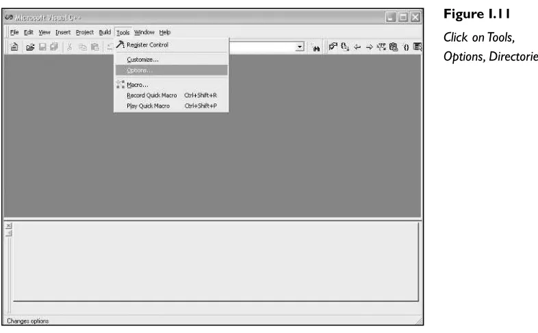
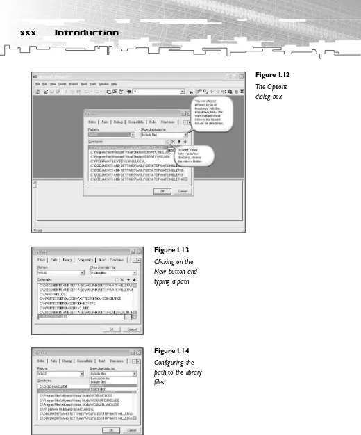
First, select Tools, Options and choose the Directories tab (see Figure I.11).
You should see something like the dialog box in Figure I.12.
The include file directories are C:\dxsdk\include and C:\DXSDK9\Samples\C++\Common\ Include. You should point your Visual C++ IDE to these directories by clicking on the New button (see Figure I.13).
These directories should always be at the top of the list because the compiler will search for the files beginning there.
After providing the include file path, you must point the IDE to the Linker Search Paths. These library files are usually in C:\dxsdk\lib (see Figure I.14).
Figure I.11
Figure I.13
Clicking on the New button and typing a path
Figure I.14
error : missing ‘;’ before ‘g_Keyboard_pDI’
Even if you provided the correct path to the header and library files, you might have to feed the names of these files to the linker of your development environment. The proper path to these object/library modules should be listed in your Link dialog box. To reach this dialog box, select Project, Settings and then choose the Link tab. In the General category, there is an entry field called Object/Library Modules. It holds all of the library files, which should be linked to the application you’re currently developing. It should look like Figure I.15.
In this entry field, you will need to name at least the following: • d3dx9.lib
• 3dxof.lib • d3d9.lib • winmm.lib • dxguid.lib
If you missed a file, an error message that might look like this will appear:
d3dapp.obj : error LNK2001: unresolved external symbol _Direct3DCreate9@4 Debug/SkinnedMesh.exe : fatal error LNK1120: 1 unresolved externals Error executing link.exe.
Figure I.15
of the common include files for the C/C++ compiler. If you change your machine or you are working on another machine with a different DirectX directory, normally you have to add the common files using Project, Add Files to Project, Files.
Now let’s compile our first project.
1. Fire up your Visual C++ configured development environment.
2. Click on Open Workspace.
3. Choose basics.dsp.
4. Check whether you’ve configured the paths to the directories as described previously.
5. Choose the Build/basics.exe build.
6. When everything works correctly, choose run basics.exe.
That’s it. If something went wrong, reread the sections on installing the DirectX SDK and Visual C++, and consult the provided documentation.
Setting Up Visual C++ .NET
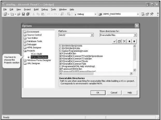
Similar to Visual C/C++ 6, the DirectX 9 SDK will set all paths for you if you install it after you install Visual C++ .NET. Nevertheless, in case anything went wrong, this section tells you what you have to do if you need to configure DirectX 9 in the Visual C++ .NET IDE manually. You start by clicking on Tools, Options in the Visual C++ .NET IDE, as shown in Figure I.16. There is a project section that holds all the paths to the relevant directories, as shown in Figure I.17.
Figure I.17
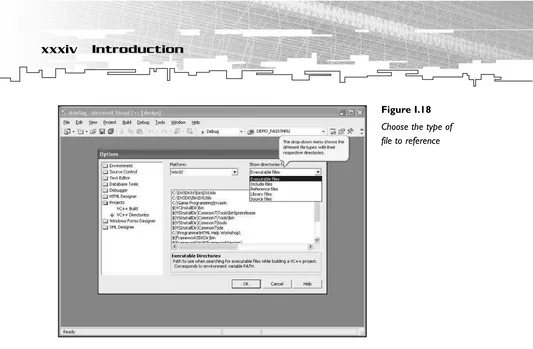
After you choose a type of file, the referenced directories will appear in the large area in the middle of the dialog box.
The include file directories are C:\dxsdk\include and C:\DXSDK9\Samples\C++\Common\ Include. You should point your Visual C++ .NET IDE to these directories by clicking on the New button and then on the ellipsis button. A default dialog box will open, allowing you to choose a directory (see Figure I.19).
Figure I.19
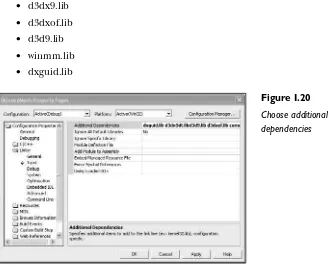
The proper path to the additional dependencies files should be listed in the Additional Dependencies field at Project, Properties, Linker, Input. In this entry field, you will need to name at least the following (see Figure I.20):
• d3dx9.lib • d3dxof.lib • d3d9.lib • winmm.lib • dxguid.lib
If any problem occurs, check out the end of the “Setting Up Visual C++ 6.0” section for solutions to common problems. The solutions are the same for Visual C++ .NET. Now let’s compile our first project.
1. Fire up your Visual C++ .NET configured development environment.
2. Click on Open Solution.
3. Choose basics.sln.
4. Check whether you’ve configured the paths to the directories as described previously.
5. Choose Debug, Start Without Debugging.
6. When everything works correctly, basics.exe will start.
Figure I.20
To debug vertex and pixel shaders, you need to install the DirectX shader debugger. This debugger is only provided for Visual C++ .NET. You can find it in the dialog box of the DirectX installation routine, as shown in Figure I.21.
By default, the shader debugger is not selected, so you have to choose it explicitly. If the computer only hosts a Visual C/C++ 6 installation, you don’t get this choice at all. The dialog box will look like Figure I.22.
Please note that only Visual C++ .NET users can use the shader debugger.
Figure I.21
Choose the shader debugger by clicking on DirectX Extensions for Visual Studio 7
Figure I.22
programmers than the compilers provided with these IDEs. However, I don’t recommend that beginners use these compilers because they overcomplicate some things. You can find more information at http://www.intel.com/software/products/compilers and at http://www.codeplay.com. While on Intel’s Web site, don’t forget to check out VTune, a profiler that helps you to optimize your game. These and the Visual C++ compilers from Microsoft are the fundamental development tools that the majority of PC game program-mers use nowadays.
Additional Resources
DirectX
Graphics:
Don’t
4
3D Fundamentals, Gouraud Shading,
and Texture-Mapping Basics
5
The Basics
CHAPTER 1
T
his chapter covers the history of Direct3D and its functional development over time. It starts with DOS and PC history, and it discusses how three British students changed the world of 3D programming.Before Windows, DOS was the most popular operating system for the PC. Games were programmed exclusively in DOS for many years. Game developers resisted developing for Windows because of its unacceptable graphics and audio performance at the time.
The direct access to hardware that DOS afforded came with its own complications, however. DOS games had to support the full range of video and audio hardware. This forced devel-opers to write complex code to support dozens of different configurations just to provide consistent graphics and audio across all PCs.
In this chapter, you will learn about:
• The history and earlier versions of DirectX, leading up to the current version • The introduction of point sprites and vertex and pixel shaders in DirectX 8 • The basics of 3D textures
DirectX 2.0
DirectX 6/7
Until the advent of DirectX 8.0, Direct3D consisted of two distinct APIs: Retained Mode and Immediate Mode. At the time, the Immediate Mode API was difficult to use, but it was a flexible, low-level API that ran as efficiently as possible. Retained Mode was built on top of Immediate Mode and provided additional services, such as frame hierarchy and animation. Retained Mode was easier to learn and use than Immediate Mode, but programmers wanted the added performance and flexibility that Immediate Mode provided. Development of the Retained Mode API has been frozen with the release of DirectX 6.0.
The major changes between Direct3D Immediate Mode versions 6.0 and 7.0 affected the support of hardware-accelerated transformation and lighting and the reorganization of the lights, materials, and viewport objects, which now are set directly by calling the methods of
IDirect3DDevice7. Direct3D 7 dropped the special interface used in Direct3D 6 to access tex-tures. The IDirect3DDrawSurface7interface also provided an easier way to manage the textures.
DirectX 8
The advent of the DirectX 8.0 SDK brought the biggest improvements in the history of Direct3D. Direct3D got a fundamentally new architecture with version 8.0. The initializa-tion, allocainitializa-tion, and management of data were simplified by the integration of DirectDraw and Direct3D into one interface, called DirectX Graphics, which led to a smaller memory footprint and a simpler programming model. It is safe to say that these changes made DirectX 8 easier to use and more consistent than OpenGL for the first time.
Some of the new features in DirectX 8 included
• Point sprites (hardware-supported sprite objects) • 3D volumetric textures (textures with three dimensions)
• An improved Direct3DXlibrary (which provided many useful and highly optimized routines)
• N-patches (which add an algorithm and vertices to a model to get a higher-tessellated model)
3D Textures
With 3D volumetric textures, you can accomplish exact per-pixel lighting effects, point- and spot-light effects, and atmospheric effects.
Direct3DX Utility Library
DirectX 8 also enhanced the Direct3DXutility library, which was introduced in DirectX 7. This library provides helper functionality for:
• Enumerating device configurations • Setting up a device
• Running full-screen or windowed mode uniformly • Running resizing operations
• Calculating vector and matrix operations
• Simplifying image-file loading and texture creation • Drawing simple shapes, sprites, and cube maps
With the release of DirectX 8, the utility library offered support for skinned meshes, multi-resolution level-of-detail (LOD) geometry, and higher-order surface data for .X files. The
D3DXimage file loader functions now support BMP, TGA, PNG, JPG, DIB, PPM, and DDS files. DirectX 8.0 also introduced helper methods to port OpenGL applications to DirectX Graphics, as well as the only higher-order surfaces that are used in current games— N-patches. These are used to tessellate models higher with the help of the graphics processor, which means you send in the data for a low-polygon model and it is tessellated (polygons are added) in the graphics card.
Vertex and Pixel Shaders
ps_3_0 pixel shader standards. Although these three pixel shader standards correspond to three hardware designs, in the past the ps_1_1 standard that was initially designed for the NVIDIA GeForce 3 was adopted by all major graphic card manufacturers, for example. There are now more equivalent software implementations for the vertex and pixel shader 2_0 and 3_0 versions, called vs_2_sw, vs_3_sw, ps_2_sw, and ps_3_sw.
To be able to write shaders in the most efficient way, an HLSL (High-Level Shader Language) was introduced in DirectX 9. This HLSL helps you write shaders faster and easier in a C-like syntax instead of the old assembly syntax. All shader examples in this book use HLSL. To keep up with OpenGL, a scissor test and line anti-aliasing were introduced with DirectX 9.0. The scissor test is performed after the fragment color is computed but before alpha testing. It determines whether the screen coordinates of a value are within the scissor rec-tangle defined by four values, and it discards fragments that are lying outside this recrec-tangle. Additionally, there is a new render state that supports the OpenGL-style sphere map texgen. (Texgen is a nickname for automatic texture-coordinate generation.) Two-sided stencil support was implemented to enable programmers to add shadow volumes to occlude geometry. (Please see the two-sided stencil example in Chapter 10, “More Advanced Shader Effects,” which shows the usage of shadow volumes.)
One feature that should soon make it into DirectX 9.0 games is the ability to render from one pixel shader to multiple render targets. (This is called a G-buffer.) You can then blend up to four render targets in another pass. A feature that is comparable but less useful than the multiple render targets is the multi-element texture. The pixel shader can store up to four textures in one multi-element texture, and it can read them from there. Displacement maps were added as a new class of higher-order surfaces, but at the time of this writing, it looks like only the Matrox Parhelia and the ATI RADEON 9700 PRO are supporting them in hardware.
Two long-awaited features of DirectX 9.0 are the support of up to 24-bit color precision and the ability to change the gamma values depending on your monitor’s gamma support. This gamma support uses very simple filters that are applied to data as it leaves a surface and before it is rendered on the screen. The so-called gamma controls don’t change the con-tents of the surface itself.
The DirectX 9.0 SDK provides a programming framework that has been used in versions since DirectX 6 and is used in all examples in this book. Starting with DirectX 8.0, this framework is called common files. You will find these files in the
you to concentrate on learning. Intermediate and professional programmers might use the framework as a good testing platform, and professional programmers might write their own framework that better suits their needs by looking at the DirectX Graphics common files source code.
Summary
T
his chapter gives you a rough overview of why the HAL (Hardware Abstraction Layer) exists, how it is used, why Microsoft used the COM (Component Object Model) interface to encapsulate the DirectX code, and how it is accessed from within the application. Both techniques enable Direct3D to provide maximum speed on different hardware, with a common interface and backward compatibility in mind. The introduction of both techniques addressed the following demands:• The API needs consistency to be viable.
• If hardware doesn’t support some features of Direct3D, there must be fallback mechanisms.
• Interface innovation must be possible with the lowest possible learning curve for programmers.
• All games developed in early versions of DirectX must be guaranteed to run in future versions of DirectX.
Hardware Abstraction Layer
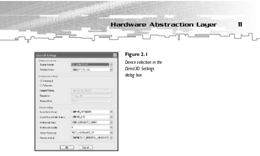
Along with the graphics card driver provided by the hardware vendor, Direct3D provides a very thin software layer around your graphics card. HAL makes up one part of this thin layer. If you’ve ever played a game driven by DirectX, you’ve seen HAL. Every game includes a drop-down menu that gives you the option to pick a device or driver. Depending on the graphics hardware, in DirectX 7.0 games you can choose a HAL, TnLHAL (Transformation and Lighting HAL), RGB, or a reference rasterizer driver from this dialog box. In DirectX 8.0/8.1/9.0 games, you might choose between a HAL, a pluggable software device, or a ref-erence rasterizer; or the application might select one automatically. You will find this device selection box, called the Direct3D Settings dialog box, in every Direct3D example program delivered with the DirectX 9.0 SDK (see Figure 2.1). Just start an example and press F2. Even if a HAL is available, the game will usually switch features on and off, depending on the features the HAL is able to provide. The process works like this:
1. The game checks the HAL’s capabilities.
2. The game switches features on or off as appropriate.
In the past, a HEL (Hardware Emulation Layer) could emulate certain features in software. However, HELs have not been provided since DirectX 8.0. If you want your games to run on ancient hardware, it would make sense to use DirectX 7.0 with its HEL (which is called an RGB device).
Like its predecessor, DirectX 9 provides an interface to use a HEL written by a software developer. This type of HEL is now called a pluggable software device. As far as I know, nobody has done that so far, which supports the fact that DirectX 8.0/8.1/9.0 games are very dependent on what the hardware is able to provide.
The overview in Figure 2.2 shows the relationships among the Direct3D API, HAL, and GDI (Graphics Device Interface) APIs.
Figure 2.2
to run DirectX 9.0 applications. To check the DDI level, run the DirectX Diagnostic Tool and examine the saved text file. You can access this tool by clicking the DxDiag button in the DirectX Properties dialog box (see Figure 2.3).
Therefore, a graphics card that will run DirectX 9.0 games must have a driver that is at least compatible with DirectX 7.
HAL is also able to emulate vertex processing in software completely or in parts. The following flags control vertex-processing behavior for HAL and reference devices:
• D3DCREATE_SOFTWARE_VERTEXPROCESSING
• D3DCREATE_HARDWARE_VERTEXPROCESSING
• D3DCREATE_MIXED_VERTEXPROCESSING
Additionally, HAL is able to switch on a so-called pure device. This device uses a reduced number of state checks and is available only if specific functions of the Direct3D API are not used. It is a bit faster than the non-pure hardware vertex-processing device. The exam-ples in the DirectX 9.0 SDK display the selected kind of vertex processing (see Figure 2.4).
Figure 2.3
HAL has four different methods of vertex processing. These include • SW VP (Software Vertex Processing)
• Mixed VP (Mixed Vertex Processing) • HW VP (Hardware Vertex Processing) • Pure VP (Pure Vertex Processing)
The behaviors of the pluggable software device and the reference device must be identical to that of the HAL device. Application code to work with the HAL device should work with the software or reference devices without modification. In fact, the reference device is the reference implementation that sets the standards, and the software device and HAL have to be measured at its functionality.
You must check the capabilities for each device, of course. The reference rasterizer sup-ports all of the Direct3D 9.0 features, whereas a pluggable software device might not even support texturing.
If there’s no hardware accelerator in a user’s machine, attempting to create a HAL device will fail.
Pluggable Software Devices
It is possible to write a hardware emulation layer (now called a pluggable software device) that runs even if the user’s computer hardware doesn’t provide all of the 3D operations required to play the game. Nowadays, the software/game manufacturer must develop the hardware emulation device, whereas in former incarnations of the DirectX run-time envi-ronment, Microsoft provided it as the RGB device. Software devices are loaded by the appli-cation and registered with the Direct3D object. The function to register a pluggable
results in a black screen.
The reference rasterizer supports all Direct3D features. You should only use it to test features that your card doesn’t support. This device is optimized for accuracy, not for speed. Direct3D does not enumerate it by default. The DirectX SDK installer will set the EnumReferencevalue in the HKEY_LOCAL_MACHINE\SOFTWARE\Microsoft\Direct3D\Drivers registry key to a non-zero DWORDvalue. Hardware, software, and the reference device cannot render to 8-bit render-target surfaces.
Controlling Devices
You can configure all controlling devices in the DirectX Properties dialog box, which you will find in the DirectX option in your computer’s Control Panel (see Figure 2.5).
Note the Enable Shader Debugging check box in the dialog box, which might be useful later. Additionally, the Debug/Retail D3D Runtime section lets you choose between the debug and retail builds, which might be useful if you want to jump back and forth between the debug and retail builds to measure retail performance.
With this HAL/pluggable software driver/reference driver approach, Microsoft guarantees a consistent API on which you can fall back if specialized 3D hardware is absent. That’s
Figure 2.5
great, isn’t it? OK, what about the other two demands specified in the beginning of this chapter: How does Direct3D handle version changes? Are they easy to learn, and are they handled so that they’re transparent to the programmer? This is where the COM interface design of the DirectX SDK helps.
COM
If you’ve used other Microsoft APIs, there’s a good chance that you’re an old COM freak and you can skip over this section. The rest of you must invest a small learning effort, but you will get a good return on your investment by learning to use the COM interface, which has been used by DirectX since its inception.
In COM terms, a software component is simply a chunk of code that provides services through interfaces, and an interface is a group of related methods. A COM component is normally a .DLL (Dynamic Link Library) file that can be accessed in a consistent and defined way. Period. It doesn’t sound like something you could write a thousand-page book about, does it? COM has many advantages. I’d like to highlight three that I think are important for Direct3D programmers like us.
• COM interfaces can never change. • COM is language-independent.
• You can only access a COM component’s methods, never its data.
C++ and many other languages are source-based; therefore, they do not have a versioning strategy. COM was designed to be a binary-based programming model. COM interfaces can never be modified in any way.
For an example of why COM is necessary, consider this scenario. Non-COM DLL A is pro-duced by software company C, whereas non-COM DLL B is propro-duced by software company D. DLLs A and B might be compatible as long as one of the companies does not change the interface of its DLL. However, if company D changes the interface of DLL B, it will be incom-patible with DLL A unless company C made the same changes to the interface of DLL A. This scenario cannot occur with a COM DLL. When a COM object is changed, a completely new interface with a new name is added to the DLL. Therefore, every COM DLL has to support the interfaces since its release. If both companies in the aforementioned scenario used a COM DLL, a change in the interface of DLL A would lead to the addition of a new interface to A. Because A would then have two interfaces, DLL B would still be able to con-nect to the old interface.
This is exactly how DirectX implements its interfaces. Direct3D 9.0 or DirectX Graphics support the following interfaces:
• IDirect3D
• IDirect3D2
• IDirect3D7
• IDirect3D8
• IDirect3D9
Table 2.1 shows the interfaces that were added to the corresponding versions of DirectX.
The newest DirectX version at the time of this writing therefore supports IDirect3Dthrough
IDirect3D9. This means that older games that use IDirect3D2can still run on current hard-ware because this interface is still supported in the newest DirectX version. In other words, if a company produces a game that is compatible with Windows NT 4.0, which only sup-ports the IDirect3D2interface of the DirectX 3.0 SDK, the company will have to use the
IDirect3D2interface for everything to work. The IDirect3D2interface has been implemented in every Direct3D DLL since the advent of DirectX 3.0, and it will be implemented in any future versions. The aforementioned game will run on every platform that runs at least the DirectX 3.0 run-time.
COM is language-independent. Whether your favorite language is Visual Basic, Pascal, or something else, you can access COM objects with your favorite compiler package. Delphi users are especially fond of this feature, but Visual Basic gurus have been provided with a fine implementation of their own in all DirectX SDKs since the arrival of DirectX 7.0. Language independence matters when parts of the game—for example, the world editor— are written in Delphi and other parts (perhaps different places in the world) are written with the Visual C++ compiler.
Table 2.1 DirectX Interfaces and Versions
DirectX Version Interface
DirectX 2 IDirect3D
DirectX 3 IDirect3D2
DirectX 6 IDirect3D3
DirectX 7 IDirect3D7
DirectX 8 IDirect3D8
COM can only be accessed via methods. You cannot access data objects directly. This is a good object-oriented design. As you will see in the next chapter, you can’t call a method directly. Instead, you have to use double indirection through a virtual function table, called the v-tableor VTBL. These v-tables are also the key to a language-independent interface. With these advantages, COM helps you get language-independent, guaranteed access to the legacy and current Direct3D interfaces. Now get access!
Summary
This chapter introduced the ideas behind HAL and COM. HAL is the main device driver of the graphics card. If HAL does not support a feature, there must be a fallback mechanism that gives the user a comparable visual experience. Alternatively, the game should run with a pluggable software device written by the game’s manufacturer.
CHAPTER 3
T
his chapter introduces the programming conventions that are used throughout the book. In this chapter, you will learn:• How to access a COM object
• The naming convention (Hungarian notation) used in the DirectX SDK and throughout this book
• Useful debugging tips for Direct3D applications • How and why to use return codes
Accessing COM Objects
When you call a method in a COM component, you have to use a v-table. When you’re deciding whether to develop your code in C or C++, you need to consider a few issues. I’ll start with an example. Suppose you want to set a light in a scene of your world-class 3D game. With C, you would use the following line of code:
hr = m_pd3dDevice->lpVtbl->SetLight(m_pd3dDevice, 0, &light );
You call the COM interface methods by passing the thispointer, called lpdd, as the first parameter of the method and by referencing the interface’s method by using it as a pointer to the interface v-table, which is called lpVtblhere (see Figure 3.1).
Although there are macros that help make C programmers’ lives easier (for example, in ddraw.h), C++ is much simpler for using COM objects. COM objects and C++ objects are binary-compatible so that compilers handle COM interfaces and C++ abstract classes in the same way. The in-memory layout in C++ of a class instance that inherits from a pure virtual base class (a class with only methods that are virtual and equal to zero) has the same mem-ory representation as a COM interface. Therefore, in C++ the lpVtblpointer is implicitly dereferenced, and the parameter is implicitly passed. Thus, the previously described call for C would look like this in C++:
hr = m_pd3dDevice->SetLight(0, &light );
v-table COM object Create
Figure 3.1
In general, most DirectX calls in C++ look like this:
lpinterface->methodname
As you saw in the Introduction to this book, you have to include a number of import libraries to compile a DirectX program.
• d3dx9.lib • d3dxof.lib • d3d9.lib • winmm.lib • dxguid.lib
Most of these libraries are import libraries that provide the interface names to the linker of your development environment.
Now that you understand that COM objects are collections of interfaces, which are simply method pointers and, more specifically, v-tables, you need to see an example of how to work with COM. There are three things of which you should be aware.
• Direct3D run-time COM objects and DLLs must be registered to and loaded by Windows. The DirectX installer will do this for you.
• You must include the previously mentioned libraries in your Windows project so that the wrapper methods you call are linked. (For more information, see the “Setting Up Visual C++ 6.0” and “Setting Up Visual C++ .NET” sections in the Introduction to this book.)
• You must include the proper include files in your source file and in the include path entry forms of your IDE (for example, Visual C++) so the compiler can see header information, prototypes, and data types for DirectX Graphics. (Again, for more information see the “Setting Up Visual C++ 6.0” and “Setting Up Visual C++ .NET” sections in the Introduction.)
The data type for an IDirect3D9interface pointer is
LPDIRECT3D9 g_pD3D = NULL;
To create an IDirect3D8COM object and retrieve an interface pointer for it, you simply need to use the Direct3DCreate9()method.
m_pD3D = Direct3DCreate9( D3D_SDK_VERSION );
The only parameter passed to Direct3DCreate9()should be D3D_SDK_VERSION. This informs Direct3D that the correct header files are being used. This value is incremented whenever a header or other change requires applications to be rebuilt. If the version does not match,
Direct3DCreate9()will fail.
The retrieved interface pointer gives you access to the interface of IDirect3D9. You might call a method in that interface, for example:
hr = m_pD3D->CreateDevice( m_d3dSettings.AdapterOrdinal(), pDeviceInfo->DevType, m_hWndFocus, behaviorFlags,
&m_d3dpp, &m_pd3dDevice );
That’s it for COM. You will use COM throughout this book. If you’re wondering about the strange and cryptic parameter names, read on for an explanation.
Naming Conventions
I use a simple variable tagging scheme that has its roots in the so-called Hungarian notation used by Microsoft for its own development projects. The name came from its inventor, Charles Simonyi, a now-legendary Microsoft programmer who happened to be Hungarian. It’s helpful to supply variables in the right format to help others read your code, but it can be confusing to people who haven’t seen the Hungarian convention.
Table 3.1 shows the prefixes I use and their respective types. You might occasionally come across other prefixes, but this table shows the common ones. Hungarian notation simply consists of prefixing variables with their types.
Although the variable-naming convention is to prefix the variables with their types, the naming convention for methodsjust clarifies readability and the purpose of the method. In all methods, the first letters of subnames are capitalized; an underscore is illegal.
HRESULT ConfirmDevice( D3DCAPS9* pCaps, DWORD dwBehavior, D3DFORMAT adapterFormat, D3DFORMAT backBufferFormat )
HRESULT EnumerateDevices( D3DAdapterInfo* pAdapterInfo, CArrayList* pAdapterFormatList )
As you can see, parameters for functionsfollow the same naming conventions as normal vari-ables. The parameter pCapspoints to a D3DCAPS9structure. The third and fourth parameters of
ConfirmDevice()use the same type to describe a surface format. You can tell that the two para-meters of EnumerateDevices()are not provided by Direct3D because they are not capitalized.
Typesand constantsbegin with an uppercase letter, but you can use underscores in the names, for example:
#define D3DPRESENT_BACK_BUFFERS_MAX 3L
You must prefix all C++ classeswith a capital C, and you must capitalize the first name of each subname, for example:
class CD3DMesh {
The CD3DMeshclass handles the loading of .X files. It’s implemented in d3dfile.h of the com-mon files. Why don’t you try it? Take a look at a typical Direct3D application class:
class CMyD3DApplication : public CD3DApplication {
CD3DFont* m_pFont; CUSTOMVERTEX m_QuadVertices[4]; LPDIRECT3DTEXTURE9 m_pCustomNormalMap; LPDIRECT3DTEXTURE9 m_pFileBasedNormalMap; D3DXVECTOR3 m_vLight;
BOOL m_bUseFileBasedTexture; BOOL m_bShowNormalMap; HRESULT CreateFileBasedNormalMap();
T
ABLE3.1 Prefixes and Types in Naming Conventions
Prefix Type Example
w WORD wSpeed
dw DWORD dwHitList
f FLOAT fSpeed
d DOUBLE dDirection
p Pointer pArray
v D3DVECTOR3 vLight
l LONG lPitch
s String sQuestion
sz String terminated by 0 szQuestion
h Handle hResult
I COM interface IDirect3D
m_p Member class pointer m_pFloorVertices
m_f Member class float m_fStartTimeKey
c Constant cText
HRESULT CreateCustomNormalMap();
HRESULT ConfirmDevice( D3DCAPS9*, DWORD, D3DFORMAT );
LRESULT MsgProc( HWND hWnd, UINT uMsg, WPARAM wParam, LPARAM lParam ); protected:
There is a member class pointer on a font class at the beginning of the code. There is also another member in the class, which uses a custom vertex structure for a quad array of vertices. Two member class pointers are pointing to Direct3D texture objects. A light vector is stored in
D3DXVECTOR3. If a file-based texture is used, m_bUseFileBasedTexturewill indicate this. If the user likes to see the normal map, the m_bShowNormalMapswitch has to be set to TRUE. As you can see in this class (taken from a file from the common files directory), the Hungarian naming conven-tion is used for all files used in the DirectX SDK.
Debugging DirectX
Debugging DirectX applications can be challenging. Following are a few tips to get you started.
• Define STRICTat the beginning of your *.cpp file before including windows.h. This leads to strict type checking, which will help you find bugs.
• Use the DXDiag utility from the DirectX SDK to report your bugs, but be sure that you know exactly what is on your system.
• The DirectX Control Panel allows you to set the debug output level from 0 to 5. To access the Control Panel, select Start, Settings, Control Panel, DirectX, Direct3D. On the same tab, you can switch from the retail to debug run-time version or vice versa. • The D3DXlibrary is a static library. To help you debug, there’s a debug-only dynamic
library of D3DX. To use it, link to d3dx9d.lib, which is an import library correspond-ing to the D3DX9D.DLL.
• You can debug vertex and pixel shaders with a plug-in for Visual .NET. I will cover this debugger in more detail in the shader section of this book.
• If you want to measure the performance of your application with something like Intel’s VTune, you should download the release symbol files from the Microsoft Web site. Usually you will use the default debug symbol files.
• The OutputDebugString()function is a useful debugging aid. It outputs debug messages in the debug window of your IDE while your program is running.
• Using a simple log file class is helpful in larger applications to show problems while the program is initializing. You can find a couple of very useful log file classes on the Internet. The example in Chapter 12, “Using *.md3 Files,” uses such a log file class. • It is quite common to use a debug texture to see whether problems with texture
alignment or filtering are occurring. Usually you try to paint such a texture with a different color or you use some text so you can see how it is aligned. Figure 3.2 provides an example.
• The Visual C++ GUI debugger can debug full-screen exclusive applications only when you are using a monitor system or remote debugging. Using a multi-monitor system is pretty common nowadays, and remote debugging is explained in the DirectX SDK help file. If you don’t have a multi-monitor system or the ability to debug remotely, it’s usually wise to build the application in a windowed mode, like the one provided by the framework that is implemented in the common files.
Return Codes
A return code is the value returned when the method is complete. It indicates the success or failure of a call and, if applicable, the reason why the call failed. Checking the return codes is simplified by the SUCCEEDED()and FAILED()macros provided with the DirectX 9.0 SDK. They take an HRESULTas an argument and return whether it indicates a success code or a failure code. Don’t try to check HRESULTagainst S_OK; not every method returns S_OKif it succeeds. A function might return S_FALSEto indicate that it did nothing because there was no need to do anything.
Figure 3.2
Because every DirectX method returns an HRESULT, you need to structure your code to check for and handle all potential errors. This work is frustrating at first, but it soon becomes second nature. Having a program that is more resistant to crashing is a good reward for the work.
Summary
CHAPTER 4
T
his chapter will give you a brief introduction to the most important 3D concepts, show you the difference between Gouraud and flat shading, and provide you with an overview of how a texture is mapped to an object. In this chapter, you’ll learn how to:• Work with vertices and orientation • Work with faces and polygons • Use Gouraud shading
• Put into practice the basics of texture mapping
3D Fundamentals
The Direct3D engine uses a left-handed coordinate system by default. Every positive axis (x, y, or z) is pointing away from the viewer. To make things a little bit clearer, Figure 4.1 shows the world coordinate system.
The positive y-axis is up, the positive x-axis is to the right, and the positive z-axis is into the screen, away from the user. The OpenGL coordinate system uses a positive z-axis that points out of the screen. This is called a right-handed coordinate system. The Direct3DXutility library has built-in functions that can help you port an application that uses the OpenGL coordinate system to the Direct3D left-handed system. As you will see in Chapter 12, “Using *.md3 Files,” Quake 3 and its .md3 file format use their own coordinate system, where the positive z-axis points up and the positive y-axis points out of the screen. However, most games use the coordinate systems used by OpenGL or Direct3D. Because we are using floating-point coordinate values, you don’t lose any precision by using numerically small units. Now on to vertices. Let’s face a square, as shown in Figure 4.2.
y
x z
1
1 2
2 2
Figure 4.1
The square uses four vertices, v1 through v4. A vertexdefines the point of intersection of one or more lines; these are straight lines as far as we are concerned. What’s the point of all this business about coordinate systems and vertices? The point is that Direct3D needs a way to place these primitives in a scene. You need something to measure distance and space, so go ahead and place your square in the coordinate system (see Figure 4.3).
To define a vertex in 3D space, you must specify three coordinate values: x, y, and z. The origin of your coordinate system is 0, 0, 0. The position of the vertices of the square could be described as
v1 (0, 0, 0) v2 (0, 2, 0) v3 (0, 2, 2) v4 (0, 0, 2)
And there you are. You can define the location of a vertex by specifying a vector from the origin to another point in 3D space. This is the so-called free vector, or zero vector, used by game programmers. Its initial point is assumed to be the origin, and only the final point is described (see Figure 4.4).
Vectors are one of the most important concepts in 3D games. They are mathematical enti-ties that describe a direction and a magnitude (which can be used for velocity, for exam-ple). Vectors are usually denoted by a bold-faced letter, such as a. Thus you could say the vector v = (1, 0, 1). The first value denotes units in the x direction, the second value denotes units in the y direction, and the third value denotes units in the z direction.
Vectors are not only used to define the position of the vertices, they are also used to define a direction. For example, the vector vUp (0, 1, 0) defines the up direction (see Figure 4.5). Note that the actual length of a vector is not important when the vector is used to define a direction or a vertex. However, the length of a vector is important sometimes, such as in the case of a normal or a light vector. You will deal with these kinds of vectors later in the book.
As you might expect, Direct3D provides two default structures for defining vectors. You’ll find the enhanced D3DXVECTOR3version of Direct3DX—theutility library—in d3dx9math.h, and the default D3DVECTORversion in d3d9types.h, which handles all the math routines you need when you use vectors. Vector v3would be defined as
D3DVECTOR v3( 0, 2, 2); // or ...
D3DXVECTOR3 v3(0, 2, 2); // used by the utility library
Understanding Vertices
A free, or zero, vector is often used to describe the position of a vertex. Nevertheless, a vertex consists of much more data than the position. If the vertex has a color, then there is a variable for the color. If it has a normal, then there is a variable that holds the vertex normal vector. If a texture is used, the vertex has variables to hold the texture coordinates. A vertex structure might look like this:
v3
Struct Vertex {
D3DVECTOR3 vPosition;
DWORD dwDiffuse; // diffuse vertex color D3DVECTOR3 vNormal; // vertex normal
FLOAT u, v; // texture coordinates of vertex }
I will explain the idea behind the terms vertex normal andtexture coordinates in the next chapter. It is important to note that a vertex is usually a structure that holds more data than the position. The Direct3D run-time is used to receive data this way. All vertices are stored in a vertex buffer that allows your example application to allocate and access memory that’s usually only accessible by the driver. I will discuss vertex buffers in more detail in Chapter 5, “The Basics.”
Working with Orientation
Measuring and organizing space in a virtual world is important for every game, but you also need a way to define the orientation of objects.
You might describe the orientation of an object by using at least four vectors—LOOK, UP,
RIGHT, and POSITION. The POSITIONvector defines the position of the object. The LOOKvector defines the way the object is pointing. The RIGHTvector defines where the right side of the object is pointing. The UPvector is necessary if the object is rotated around the LOOKvector. The UPvector tells you when the object is considered up or down.
You can rotate the object around the vectors. If you want to change the pitch of an aircraft, you might rotate it around the RIGHTvector. If you want to roll the aircraft, you might rotate it around the LOOKvector. If you want to change the direction the aircraft is facing (the yaw), you might rotate it around the UPvector. If you want to move the object in the direction the
LOOKvector is facing, you might change the POSITIONvector.
Understanding Faces
Any 3D object consists of faces, as shown in Figure 4.6.
v2 v3
v1 v4
Figure 4.6
To create a smooth-looking object, you need hundreds or even thousands of faces or sur-faces, as shown in Figure 4.7.
Every model and 3D world is broken down into points, lines, and triangles, the only primi-tives Direct3D is able to render. If you design your shapes using polygons with four or more vertices to reduce the number of faces, Direct3D will divide every face into triangles. To get optimal performance, you should make every object easily divisible into triangles.
Therefore, you should usually use triangles to construct your object. An object consisting of several triangles like the cube shown in Figure 4.7 is called a mesh.
Figure 4.8 shows a more complex mesh, which consists of nine faces from ten triangles.
One final point you need to be aware of is that Direct3D can cull back faces. The Backface Culling feature removes all triangles that are facing away from the viewer or camera. These are by default the vertices that are grouped counter-clockwise. On average, half of your game world triangles will be facing away from the camera at any given time, so this helps to reduce rendering time. Depending on what is going to be rendered, you can switch off Backface Culling with the D3DCULL_NONEflag. Backface Culling uses the cross-product of two sides of a triangle to calculate a vector that is perpendicular to the plane that is formed by the two sides. This vector is the face normal, and the direction of this normal determines whether the triangle faces frontward or backward. Because the Direct3D API always uses the same vertex order to calculate the cross-product, you know whether a triangle’s vertices are “wound” clockwise or counter-clockwise. You can read more about the cross-product in Appendix C, “Mathematics Primer.”
Figure 4.7
A cube constructed of triangles
Figure 4.8
Understanding Polygons
A polygon can be defined in either 2D or 3D space; in our case, we will refer to polygons as n-sided closed figures defined by at least three vertices. The simplest polygon is a triangle. Direct3D uses triangles to compose most polygons because all three vertices in a triangle are guaranteed to be co-planar; rendering non-planar vertices would be inefficient.
Understanding Normals
Normals are perpendicular vectors that can be used to define the direction a face is pointing or the visible side of a face (see Figure 4.9).
A vertex normalis often perpendicular to a face, and it usually sits upon the vertex as one unit long. The other type of normal is a face normal. It is usually perpendicular to a face and sits in the middle of the face. You don’t have to worry about this kind of normal because Direct3D calculates them automatically. Vertex normals are important for lighting calculations, as you will see in Chapter 9, “Shader Programming with the High-Level Shader Language.”
Furthermore, face and vertex normals are also important for the shading mode. Whereas face normals are used for flat shading, for example, vertex normals are used for Gouraud shading.
Understanding Normals and
Gouraud Shading
The vertex normal vector is used in Gouraud shading mode (the default shading mode since the advent of Direct3D 6.0) to control lighting and to make some texturing effects. So what’s a shading mode? Shading is the process of performing lighting computations and determining pixel colors from them. These pixel colors are later drawn on the object. (More technically, shading is the way the rasterizer “shades” pixels.) Flat shading lights per polygon or face, and Gouraud shading lights per vertex (see Figure 4.10).
y
x z
2
vertex normal
Figure 4.9