Ultra Strengthening of Wooden Girders
Darwish, A.M. 1)
Abstract: Owing to the natural defects of wood, structural timber is currently used with conservative safety factors. This study investigates the use of Carbon Fiber Reinforced Polymer (CFRP) for improving the strength of structural timber. Four flexural test stages were carried out, the modes of failure of the three specimens in each stage were studied to determine and strengthen the suspected weak zone which caused the failure. It was found that the tensioned fibers of ordinary timber girders normally fail first especially at the sections containing knots. Using a strip of CFRP to strengthen tensioned fibers is a well known technology, but it will not prevent a premature failure due to horizontal shear. A strength increase of 56% was reached by the adaption of shear connectors in the form of screws. After treating tensile and shearing strengths, still testing specimens showed failure at the compressed fibers. By enhancing the compressed fibers with a steel strip, the prototype girders showed a remarkable increase in flexural strength of about 175% compared with the ordinary wooden girders having the same dimensions.
Keywords
:
CFRP, shear connectors, timber girders, ultra- strengthening.Introduction
As a natural material, structural timber has some defects that can occur at various stages of its useful life. Any of these defects can cause problems as they either reduce the strength of the structural timber or mar its appearance. Knots are perhaps the most obvious natural defect, and they detract from strength by interrupting the fiber continuity especially when they are situated in a tension zone.
In order to deal with this defect, BS 4978 [1] uses visual stress grading which specifies the maximum size of defects acceptable in each of the following different stress grades: General Structural (GS) having a working stress of approximately 40-50 percent of its basic stress or Special Structural (SS) corresponding to a working stress of approximately 65 percent of its basic stress.
It has been found that for timber containing defects, there is a direct relationship between the deflection of a short length under a small transverse load and the transverse load required to cause failure. In other words there is a direct relationship between the stiffness and the bending strength. Thus nondestructive tests have been used to determine the strength of each timber element.
1 Building and Construction Engineering Faculty, University of
Technology, Baghdad, Iraq Email: [email protected]
Note: Discussion is expected before November, 1st 2010, and will be
published in the “Civil Engineering Dimension” volume 13, number 1, March 2011.
Received 20 March 2010; revised 5 June 2010; accepted 10 June 2010.
This method has led to the development of mechanical stress grading. The mechanical grade designations normallyused for General and Special Structural are MGS, MSS (as for visual grading), M50, M75 means working stress equal to 50, 75 percent of basic stress respectively [2].
There have been many studies done to upgrade structural timber properties. Plevris and Triantafillou [3] had investigated the response of timber beams reinforced with Carbon Fiber Sheets. Schober and Rautenstrauch [4] studied the possibility of strengthening existing timber floors under bending loads. Through their investigations they have tested three different schemes of 3.25 m long beams. Type-1 was externally reinforced with Carbon Fibers Reinforced Polymer (CRFP) glued by epoxy to the beam bottom surface, while both Types-2 and 3 were internally reinforced with the same materials, as shown in Fig 1.
Type-1 1×1.4×50 mm CFRP bonded centrally to the tension zone, horizontal on bottom.
Type-2 2×1.4×25 mm CFRP bonded laterally to the tension zone 3cm from bottom in slot
Type-3 1×1.4×250 mm CFRP bonded centrally to the tension zone, vertical on bottom.
Specimens of Types 1 and 3 had reached their ultimate load within the linear range with an average breaking load of 50 and 62 kN respectively, while specimen of Type 2 could not support any further loading beyond the stage of showing its first crack and it was ruptured under an average load of 49 kN. In spite of proving that there is an increase of 5.86% in load bearing capacity, it should be noted that there are some comments upon the whole procedure, as follows:
• Specimen of Type 1 is subjected to a lateral sway, especially when the beam gets longer.
• Specimen of Type 2 is subjected to a premature failure due to the splitting of the wooden layers.
• Both of Specimens of Types 2 and 3 are difficult to be constructed.
• The gain in strength is limited.
Ehsani et al. [5] had managed to strengthen existing glulam floor beams in high school gymnasium in Arizona, USA. The retrofit system utilized is shown in Fig 2. It consists of strengthening the bottom, sides, and again the bottom and the two sides with CFRP bonded to the retrofitted beams by epoxy. This procedure increases the strength of the 4.25 m long beams by 67%.
Figure 2. Wooden beams strengthened by CFRP [5]
However, the drawbacks of the aforementioned procedure are:
• The procedure is difficult to apply, especially the proper insertion of CFRP strips in the upper slots and filling all cut by epoxy.
• If the retrofitted element is a girder, it will be very difficult, if not impossible, to attach the cross beams.
• The application of double mesh strengthening to the bottom fibers is not justified, because the expected compression failure will initiate at the top fibers before reaching the full strength of the double CFRP strips.
• A lot of expensive materials (CFRP and Epoxy) have to be used.
In this paper a multi-step testing procedure was done. Wooden girders were subjected to loads till failure. By analyzing each mode of rupture, combined with the knowledge of timber properties and defects, special multi reinforcements were used and tested to show a remarkable improvement in the moment and
shear carrying capacities of the strengthened specimens.
Testing Program
Materials
The following materials and properties have been used during all the test stages:
• Straight 3.2 m long white wood beams, each with a rectangular cross section of 10×15 cm.
• CFRP (one mm thick), having a tensile strength of 2400 MPa.
• Commercial Cold-Curing Epoxy, having the following properties:
- Tensile strength 15 MPa. - Compressive strength 70 MPa. - Shear strength 15 MPa. - Young’s modulus 4000 MPa. - Density 1400 kg/m3.
• Wooden Screws (150 mm long), each with a diameter of 5 mm and an ultimate shear strength of 5000 N/ Screw.
• Steel strip (six mm thick), having an ultimate tensile strength of 414 MPa.
Testing Procedure
Flexural strength tests have been carried out for four groups. Each group consisted of three timber beams. Loads were applied up to failure limits and the relative final deflections were recorded. While the overall dimensions were conserved, strengthening type has been modified in each stage according to the analysis of the rupture mode observed in the previous stage. Details of the four stages are as follows:
Stage-1 - Three beams without any strengthening; have been tested as a reference by applying two equal concentrated forces, as shown in Fig 3. Mid span deflections increased with the increase of the applied load, recording its average maximum of 78 mm when the beams started to fail by tension failure of its bottom fibers. Average breaking load was 16 kN.
Stage-2 -A (1×100) mm strip of CFRP was attached by epoxy to the bottom fibers of the testing beams, as shown in Fig- 4. Load was increased gradually, until an average deflection of 56 mm was recorded. A combined sudden mode of failure occurred starting with a development of horizontal cracks along the lower third of the specimen’s height trying to separate it in to two pieces, at the same time no more load can be carried by the beam and it was fractured directly under one of the applied loads. The average breaking load for the three specimens was 19 kN.
Figure 4. Dimension, loading and mode of failure of the CFRP strengthened beam (Stage-2).
Stage-3 -In addition to the strengthening method used in the previous stage, 21 vertical holes of 4mm diameter and 140 mm deep have been drilled along the top longitudinal centre line. Wooden screws have been driven inside these holes as shown in Fig 5. More loads were recorded to deflect the tested beams to an average of 45 mm. Then a compression failure of the top fibers occurred under an average breaking load of 25 kN.
Figure 5. Dimension, loading and mode of failure of the CFRP+ Wooden screws strengthened beam (Stage-3).
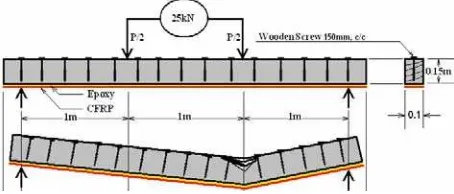
Stage-4 -A steel strip of 6 mm thick was attached to the beam top fibers as shown in Fig 6. Double holes each of 5 mm diameter and 100 mm on centers were drilled along the steel strip to allow the 62 wooden screws to pass through. The bottom fibers were strengthened by the same method used in the previous two stages. During loading process, stiffer specimens were noted compared with the specimens used in the last three testing stages. More loads were required to break the beams; less deflection was
monitored before the final failure. Maximum average deflection of 32 mm was recorded just before failure, which happened under a crushing average load of 44 kN. At this stage sudden collapse occurred due to the breaking of the CFRP under tension.
Figure 6. Dimension, loading and mode of failure of the CFRP+ Double wooden screws+ Steel plate strengthened beam (Stage-4)
Results, Calculations and Comments
Testing procedure was carried out according to the understanding of structural timber properties and defects. Modes of failure, for the three samples in each of the four stages, were analyzed to figure out their major cause of rupture. Enhancement was applied to the diagnosed weak part and the new specimen was transferred to the next stage.
In Stage-1, an ordinary timber beam, without any strengthening scheme, was tested as a reference of comparison with the improved models. It showed a linear response of deflection with respect to the applied two points testing load. Before reaching the breaking load clear signs of failure were monitored, especially the formation of cracks around the weakest section, which was situated in between the two loading points. It was noted that failure section always contains a natural knot which reduces its tensile strength due to the fiber discontinuity. In another word, all the three specimens were prematurely failed due to flexural tensile failure of their bottom fibers.
layers of the solid beam into two segments. The summation of the moment of inertias of the two segments is less than that of the original solid beam, and that was the explanation of the sudden failure. All former researchers had faced this problem which forced them to use an uneconomical CFRP jacket to wrap their retrofitted beams or otherwise they accepted a limited increase of strength. In the present test the increase was +18% compared with the strength of the natural beam of Stage-1. It should be noted here that the CFRP was not stretched to its full tensile strength, but it succeeded to bridge the weak timber sections caused by the presence of the knots.
The following calculations show the magnitude of the horizontal shear stress which caused the failure. Maximum vertical shear force from Stage-2,
V = 19000/2 = 9500 N (1)
The section properties are those with CFRP transformed on the basis of a CRFP/ wood modular ratio of, n1 = 40 (Fig 7).
Figure 7. Transformed section Dimensions.
The static moment (Q) of the transformed tensioned wooden area about neutral axis of the entire section is given by:
The moment of inertia (I) of the entire transformed section is:
It is believed that timber fibers could reach its ultimate tensile/ compressive strength if premature horizontal shear failure is eliminated. To attend this situation in Stage-3, 21 shear connectors in the form of screws having a diameter of 5 mm, spaced at 150 mm c/c, were used. This reinforcement had increased the beam resistance to horizontal shear failure (Rr) by:
This gives an additional increase of horizontal shear resistance by:
During the test, it was found that the section fails due to compression at its top fibers. That happened before reaching the full strength of either the CFRP or the shear connectors. The maximum average crushing load of the three specimens was 25 kN. Maximum average deflection just before failure was 45 mm which was less than that for Stage-2 by 20%, and less than what had been recorded for Stage-1 by 42%. In this stage, it is believed that the full flexural strength of timber had been developed but not for the CFRP.
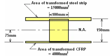
In Stage-4, for further increase in strength and for full development of CFRP Tensile strength, a steel plate was used to strengthen the top fibers of the beam. The steel plate was chosen to have a compressive strength approximately equal in magnitude to the tensile strength of the CFRP strip; that was a steel strip of a thickness equal to 6 mm. In calculating the required number of shear connectors, the section was transformed again with a steel/ wood modular ratio of, n2 = 25 (Fig. 8)
Figure 8. Dimensions used to calculate transformed section properties.
Static moment of transformed tensioned wooden area about neutral axis of entire section is:
3
The second moment of area of the entire transformed section is given by:
4
The horizontal shear is given by:
The net shear required to be carried by shear connectors is 190 - 92 = 98 N/mm. The required number of shear connecting screws is 5000/98 = 51 screws. Therefore, it is proposed that double screws at 100 mm c/c (62 screws) have to be used.
Test results show that the section becomes stiffer. It could sustain an average breaking load of 44 kN with a maximum average deflection of 32 mm just before the complete tensile failure of the CFRP. The increased load carrying capacity of this strengthened girder was equal to 175% compared with the strength of the reference specimen. The maximum deflection was just 41% of the recorded deflection of the un- strengthened girder. It is clear that by increasing the amount of each of the CFRP, the steel plate and the shear connecting screws, a further increase of strength can be achieved. The limit of this expected increment was not specified in this research, but it is expected that the bearing of the shear connectors will put an end to it.
Conclusions
The following conclusions may be drawn from this study:
1. Normally, the tensioned fibers of a structural timber girder subjected to flexural stresses fail first. This type of failure occurs due to the natural properties and defects of wood.
2. The use of CFRP for strengthening the tensioned wooden fibers can bridge the weak sections and improve the overall strength of the member to some extent, but it can not prevent a premature horizontal shear failure.
3. The use of steel connectors, in the form of wooden screws, can prevent the premature horizontal shear failure. In spite of the fact that this solution takes advantage of the full strength of the member, it can neither prevent the failure of the compressed fibers under ultimate load nor able to develop the full strength of the CFRP.
4. The use of a steel plate to strengthen the compressed fibers of a wooden girder, in addition to the mentioned reinforcements in points 2 and 3 above, can remarkably improve its flexural strength up to 175%.
References
1. BS 4978 (1973). Timber Grades for Structural Use, 1973.
2. Jackson, N. and Dhir, R., Civil Engineering
Materials, 4th Edition, Macmillan Education Ltd,
Hampshire, UK, 1988.
3. Plevris, N. and Triantafillou, T.C., FRP Reinforced Wood as Structural Material, Journal
of Materials in Civil Engineering, ASCE, 4(3),
1992, pp. 300-315.
4. Schober, K.U. and Rautenstrauch, K., Experimen-tal Investigation on Flexural Strengthening of Timber Structures with CFRP, Proceedings of the International Symposium on Bond Behavior of
FRP in Structures, Weimar, Germany, 2005, pp.
457-463.
5. Ehsani, M., Larsen, S.E., and Palmer, N., Strengthening of Old Wood with New Technology,
![Figure 1. Wooden beams strengthened by CFRP [4]](https://thumb-ap.123doks.com/thumbv2/123dok/3672730.1469780/1.595.315.538.598.693/figure-wooden-beams-strengthened-cfrp.webp)
![Figure 2. Wooden beams strengthened by CFRP [5]](https://thumb-ap.123doks.com/thumbv2/123dok/3672730.1469780/2.595.300.525.642.752/figure-wooden-beams-strengthened-cfrp.webp)