IMPROVEMENT OF TRADITIONAL ESR PERFORMANCE FOR RAPID
DETECTION OF FREE RADICALS IN MATERIALS
1Didik R. Santoso, 2Chomsin S. Widodo, 3Unggul P. Juswono
Physics Department, Brawijaya University, Jl. Veteran 2 Malang 65145, Indonesia Email: 1[email protected], 2[email protected], 3[email protected]
ABSTRACT
To detect the presence of free radicals in materials, a traditional Electron Spin Resonance (ESR) requires repeating setting values of the external magnetic field (B0) as
well as the frequency of microwave signal () to achieve resonance conditions, and it must be conducted manually. The procedure requires considerable time, so that become ineffective. In this paper, we propose a simple technique to improve the functionality of the traditional ESR by implementation of ramp-type magnetic field and high-speed data acquisition system. In here, we generate ramp-type voltage signal based on PIC16F876 microcontroller as the main device. This signal is converted to the current source by using the circuit of V to I converter, then injected to the Helmholtz coil to generate a ramp-type magnetic field. Some experiments are carried out in order to make validation and determine the performance of the developed system. By the technique, the traditional ESR becomes an automatic ESR-spectrometer and has the capability to identify some kinds of free radicals faster.
Keywords: ESR, free-radical, ramp-B.
1. INTRODUCTION
A free radical is atoms or molecules that are unstable and reactive. The existence of free radicals can be anywhere, including in the foods and others biological tissue. In high concentrations, free radicals can damage the parts of a living cell. Free radicals are believed to play a role as a cause of several diseases, such as diabetes, high blood pressure, stroke, and cancer (Halliwell and Gutteridge, 2007; Lobo et al., 2010; Rani and Yadav, 2015).
Identification of existence of free radicals can be conducted by several different methods,
either chemical or physical. In the physical method, the identification is usually conducted by using an Electron Spin Resonance (ESR) or sometimes called as an Electron Paramagnetic Resonance (EPR) (Skinner, 2011; Hawkins and Davies, 2014). ESR or EPR is a technique for detecting molecules or ions, which have one or more unpaired electrons by using the principle of resonance energy. The Resonance conditions on the ESR will occur when the unpaired electron absorbs an electromagnetic energy that has corresponding to their excitation energy level (Weil and Bolton, 2007; Wertz and Bolton, 1986).
To identify the presence of free radicals in a substances sample, the ESR use Lande-factor (g), which is derived from the relationship between the strength of external magnetic field (B0) and the frequency of microwave ()
(Serway and Jewett, 2008). In this case, is generated by microwave coil, and B0 is
generated by pairs of Helmholtz coils after injected electrical current. Both of them are main parts of the ESR equipment (Ralph; Leybold).
Furthermore, on the traditional ESR equipment, the parameter of usually set in several fix frequency values, while parameter of B0 set in sine-modulated fix value. In this
case, to find out of a free radical in an experiment, the value of as well as B0 should
be tuned manually, until resonance condition occurred. However, due to the complicated in the operation procedure, as well as limitation in the use of energy-range, the traditional ESR as mentioned above, was not possible to find some kinds of free radicals quickly. It will take a bit long times, and then make it ineffective.
In this paper, we propose a simple technique to improve the functionality of the traditional ESR by implement ramp-type and a wider range of external magnetic field B0. In
and will be linearly changed as a function of time, automatically. With this technique, the values of “g” (free radicals) can be identified and performed quickly.
2. BASIC PRINCIPLES OF ESR
2.1. ESR Theory
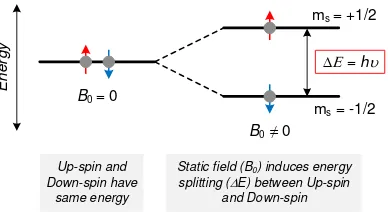
The basic principle of the ESR method is the absorption of electromagnetic energy by the particles when they are inside a strong magnetic field. According to quantum theory, each electron has a magnetic moment of the spin quantum number S=1/2, with magnetic components ms = +1/2 and ms = -1/2.
In the presence of an external magnetic field with strength B0, the magnetic field
provided will interact with the magnetic moment, which will change the atomic energy levels of -μB0. The electron's magnetic
moment aligns itself either parallel (ms = 1/2, up-spin) or antiparallel (ms = -1/2, down-spin) to the field, each alignment having a specific energy due to the Zeeman Effect (Serway and Jewett, 2008). This interaction will cause resonance conditions when electrons absorb the radiation of electromagnetic energy, which has equal to the energy splitting between up and down spin, as illustrated in Figure 1 (Weckhuysen et al, 2004).
Figure1. Influence B0 to the electron spins
Resonance absorption occurs when energy of the being absorbed is the same as the difference in magnetic energy between the two levels. Changes in the level of energy (E)
occurring between two energy levels with Δms
= ± 1 are given by:
0 B E g B h
, or (1)
0
B
h g
B
(2)
with:
h : Planck constant (6,626 x 10-34 J.s) υ : Frequency of electromagnetic (Hz)
g : Lande-factor (dimensionless) μB : Bohr magneton (9,274 x 10-24 J.T-1) B0 : External magnetic field (Tesla)
Based on Equation (2), to determine the Lande-factor (g-factor), we must measure and calculate the ratio of microwave frequency () to the external magnetic field (B0). Here, the
g-factor is a dimensionless constant; the value depends on the orientation of molecules in a magnetic field and electron structure of molecules. The g-factor of free electrons is 2.0023, and for most free radicals is between value of 1.9 to 2.1 (Togo, 2004).
2.2. Traditional ESR Instrumentation
One of most popular ESR equipment is Leybold-ESR. It was manufactured by Leybold GmbH, and used for educational purposes. This equipment contains several apparatus, including the ESR basic unit, control unit, pair of Helmholtz coils, oscilloscope, etc. The equipment can be operated within frequency range of 15 MHz to 130 MHz. Injected current to Helmholtz coils can be 0.13 A to 1.11 A or corresponding to the magnetic field of 0.55 mT to 4.65 mT (Leybold manual book P6.2.6.2).
Figure 2. Leybold ESR experimental setup Experimental setup for the identification of free radpicals by using Leybold-ESR is given in Figure 2. The experiment is set by placing a sample in the microwave coil and tune the frequency and magnetic field until resonance condition occurred. If the resonance
ms = +1/2
ms = -1/2
B0 = 0
B0 ≠ 0
E = h
Up-spin and Down-spin have
same energy
Static field (B0) induces energy
splitting (E) between Up-spin and Down-spin
En
e
rg
y
1
condition is fulfilled, the sample absorbs energy and the oscillating circuit is loaded.
The measuring signal reaches the output of the control unit with a time delay relative to the modulated magnetic field. The time delay can be compensated as a phase shift in the control unit. A two-channel oscilloscope in X-Y operation displays the measuring signal together with a voltage that is proportional to the magnetic field as a resonance signal. The resonance signal is symmetric (V-curve) if the equi-directional field B0 fulfils the resonance
condition and the phase shifts between the measuring signal and the modulated magnetic field is compensated. Based on the explanation above, to detect some kinds of free radicals in the sample, the Leybold-ESR (P6.2.6.2) requires repeating setting values of external magnetic field B0 as well as microwave
frequency, and it is must be conducted manually. The procedure will require considerable time, and become ineffective.
3. TECHNIQUE TO IMPROVEMENT
In principle, the traditional ERS on the operation uses modulated fixed external magnetic value B0. Thus the resonance curve
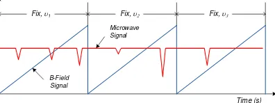
formed is basically only corresponding to one value of "g". If any one of the external magnetic or frequency values can be set on a wide area, it is possible to obtain resonance conditions at the other "g" values. This means that other types of free radicals will be obtained. Technically, setting the variable on an external magnetic field is much easier than setting the variable on frequency. So in this project that is set variable is the external magnetic field. Figure 3 illustrates the method of scanning the B0 on a wide area, for fixing
microwave frequencies 1, 2, and 3.
Figure 3. Illustration of scanning B0 on
the 1, 2, and 3.
3.1. Ramp Voltage Generator
Firstly, we generate ramp-voltage signal with peak of 5 volt and variable in time-cycle. Here, we use a microcontroller PIC16F876 as main device. The PIC16F876 is midrange microcontroller manufactured by Microchip. The device is low cost but powerfull, and suitable as main part of control system (Santoso, 2011; Microchips). Block diagram of the system is given in Figure 4.
Figure 4. Block diagram of the ramp-voltage generator
In the figure, the microcontroller generates digital code in the form of a binary code of 12 bits ranging from 000H up to FFFH, and stored in its internal memory. This digital code is then given to DAC 12 bits (MCP4725) to be converted into analog signals. The output signal from DAC is buffered to keep the stability of the formed voltage signal. The voltage ramp signal, captured by Picoscope is given in Figure 5. As seen in the figure, the ramp-voltage that has been produced by this method has a very good shape, worth starting at 0 volts and rising periodically up to 5 volts. The voltage signal is a pure ramp and almost has no noise.
Figure 5. Ramp-voltage signal 3.2. Voltage to Current Converter
It is important to understand that what the injected to the Helmholtz coil (to produce a magnetic field) is a current rather than a voltage. Therefore, we need to convert the voltage signal into the current signal. Here, after we have the ramp-voltage signal, the
Time (s) Fix, 1 Fix, 2 Fix, 3
B-Field Signal
Microwave Signal
5 Volts
signal is then converted to the current by using a circuit of V to I converter. For this purpose, we use circuit as shown in Figure 6.
Figure 6. Voltage (V) to current (I) converter
In Figure 6, the circuit of voltage amplifier is optional. Its function is to keep the voltage to be converted to its current value is stable at the lowest limit of 0 volts and the highest limit of 5 volts. Further, the main component of the V to I circuit is Darlington Transistor (Q2: TIP141) that is controlled by JFET (Q1: 2N5457). The current source then injected to the Helmholtz coil to generate a ramp magnetic field. Validation and characterization are performed to determine the performance of the developed system.
Figure 7 shows the results of laboratory tests of the circuit. We can see that relationship between voltage and current is linear by several gains. However, the relationship between current and magnetics fields is linear when current rises, but it does not follow current source while resetting to zero position. The magnetic field needs time to become zero, and this is related to the nature of the inductor (Helmholtz coil) which stores electrical energy.
Figure 7. Relationship between Voltage (V) and Current (I) and Magnetics Field
3.3. Implementation
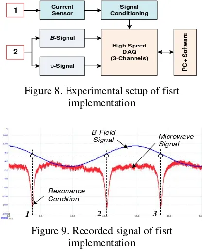
The first implementation is carried out to record magnetic field signal B0 and microwave
signal automatically and simultaneously by using high-speed DAQ and several developed systems. Experimental setup of the on this activity is given in Figure 8, while recorded signal of the experiment is given in Figure 9.
Figure 8. Experimental setup of fisrt implementation
Figure 9. Recorded signal of fisrt implementation
Next experiment is carried out to verify the implementation of the developed ramp magnetic field on the traditional ESR equipment. In this experiment, we replace modulated fix magnetic field by developed ramp magnetic field. Here, use same frequency of microwave signal (). The result of the experiment is given in Figure 10.
Figure 10. Applied ramp B0 on the traditional
ESR equipment.
1 Current Sensor ConditioningSignal
4. CONCLUSION
A traditional ESR has no ability to find some free radicals in materials rapidly, due to the complicated on the operation procedure and limitation in the use of energy-range. In this paper, we propose a simple technique to improve the functionality of the traditional ESR by the implementation of a ramp current to produce ramp magnetic field B0. By the
technique and using high-speed DAQ, the traditional ESR equipment becomes the ESR-spectrometer, and has the capability to identify some kinds of free radicals faster. For further development, what needs to be improved is the resolution of g-factor obtained, but still using low energy.
ACKNOWLEDGEMENT
This Research was supported by “DIKTI” in
the Scheme of “PUPT-UB Research Grand”
under contract no. 360.18/UN10.21/PG/2016.
REFERENCES
Halliwell B., Gutteridge J.M.C., 2007, Free Radical in Biology and Medicine, 4th Ed. Oxford University Press, New York. Hawkins C.L., Davies M.J., 2014, Detection
and characterisation of radicals in biological materials using EPR methodology, Biochimica et Biophysica Acta, Vol.1840: pp. 708–721.
Leybold, Electron spin resonance at DPPH, (https://www.leybold-shop.com).
Lobo V., Patil A., Phatak A., Chandra N., 2010, Free radicals, antioxidants, and functional foods: Impact on human health, Pharmacogn Rev. Vol. 4(8): pp. 118–126.
Microchip, PIC16F87X Data Sheet 28/40-pin 8-bit CMOS Flash Microcontroller. (www.microchip.com/PIC16F876). Ralph T.W., Modern EPR Applications,
Bruker-EPR, (https://www.bruker.com). Rani V., Yadav U.C.S., 2015, Free Radicals in Human Health and Diseases, Springer New Delhi.
Santoso D.R., Nurriyah L., 2011, Development of a simple traffic sensor and system with vehicle classification based on PVDF film element, Sensors & Transducers Vol. 126 (3): pp. 74-80. Serway R.A., Jewett J.W., 2008, Physics for
Scientists and Engineers with Modern Physics,8th Ed., Sounders College, USA. Skinner A.R., 2011, Current topics in ESR
dating, Radiation Measurements Vol. 46: pp. 749-753.
Togo H., 2004, Advanced Free Radical Reactions for Organic Synthesis, Elsevier B.V.
Weckhuysen B.M., Heidler R., Schoonheydt R.A., 2004, Electron Spin Resonance Spectroscopy, Mol. Sieves Vol. 4: pp. 295–335.
Weil J.A., Bolton J.R., 2007, Electron Paramagnetic Resonance: Elementary Theory and Practical Applications 2nd Ed., John Wiley & Sons.