Manajemen dan Rekayasa Struktur C-75
TWO NEW REFINED SHEAR DISPLACEMENT MODELS
FOR FUNCTIONALLY GRADED SANDWICH PLATES
ADDA BEDIA El Abbas(1) , MERDACI Slimane(1), ZIDI Mohamed(1), HEBALI Habib(1), BACHIR BOUIADJRA Rabbab(2), TOUNSI Abdelouahed(1), BENYOUCEF Samir(1),
BOURADA Mohamed
1. INTRODUCTION
(1)
(1) Laboratoire des Matériaux et Hydrologie, Université de Sidi Bel Abbes, BP 89 Cité Ben M’hidi 22000 Sidi Bel Abbes, Algérie.
(2) Université de Sciences et Technologie d’Oran (USTO), Algérie.
Abstract— Two refined displacement models, RSDT1 and RSDT2, are developed for a bending analysis of functionally graded sandwich plates. Unlike any other theory, the number of unknown functions involved is only four, as against five in case of other shear deformation theories. The developed models are variationally consistent, have strong similarity with classical plate theory in many aspects, doe not require shear correction factor, and give rise to transverse shear stress variation such that the transverse shear stresses vary parabolically across the thickness satisfying shear stress free surface conditions. The accuracy of the analysis presented is demonstrated by comparing the results with solutions derived from other higher-order models. The functionally graded layers are assumed to have isotropic, two-constituent material distribution through the thickness, and the modulus of elasticity, Poisson’s ratio of the faces, and thermal expansion coefficients are assumed to vary according to a power law distribution in terms of the volume fractions of the constituents. The core layer is still homogeneous and made of an isotropic ceramic material. Numerical results for deflections and stresses of functionally graded metal–ceramic plates are investigated. It can be concluded that the proposed models are accurate and simple in solving the bending behavior of functionally graded plates.
Keywords— functionally graded plates, shear deformation, higher-order theories
In recent decades, a new class of plates/shells made up of functionally graded materials (FGM), in which the material properties continuously vary through the thickness has become popular in various engineering applications. Because of the feature of continuously distributed material properties in FGM plates/shells, some drawbacks of conventional multilayered composite
Manajemen dan Rekayasa Struktur C-76
numerical modeling for the analysis of this class of FGM plates and shells has attracted considerable attention from researchers [1 – 7].
x x, y, and z coordinate directions, respectively, and u0, v0, and w0 displacements.
However, in thick and moderately thick plates, the transverse shear strains have to be taken into account. There are numerous plate theories that include these strains. The first-order shear deformation plate theory (FSDPT), which is known as the Mindlin plate theory [8 – 10], considers the displacement field as linear variations of midplane displacements:
, v(x,y,z)=v0+zθy,
In this theory, the relation between the resultant shear forces and the shear strains depends on shear correction factors [11 – 13]. This theory is also used for FGM plates as is described by Sladek et al. [14].
Some other plate theories, e.g., higher-order shear deformation theories (HSDT), which include the effect of transverse shear strains, are reported in the literature.
Higher-order theories based on series
expansions were developed by Donnel
[15], Reissner [16], and Lo et al. [17, 18]
and were modified by Levinson [19],
Murthy [20], and Reddy [21]. The
displacement field in these theories is
x
Reddy [21, 22] put forward a parabolic shear deformation plate theory (PSDPT) which considers not only the transverse shear strains, but also their parabolic variation across the plate thickness. As a result, there is no need to use shear correction coefficients in computing the shear stresses. In this theory,
x
Touratier [23] used sinusoidal shear deformation plate theory (SSDPT) for describing the parabolic distribution of transverse shear strains across the plate thickness and took the displacement field in the form
Soldatos [24] employed hyperbolic shear deformation plate theory (HSDPT) for this purpose:
x
Karama et al. [25] used an exponential
shear deformation plate theory (ESDPT):
Manajemen dan Rekayasa Struktur C-77 ( )
x h z ze x w z u z y x
u 0 2 / 2θ
0 ) , ,
( + −
∂ ∂ −
= ,
( )
y h z ze y w z v z y x
v 0 2 / 2θ
0 ) , ,
( + −
∂ ∂ −
= ,
) , ( ) , ,
(x y z w0 x y
w =
Ferreira et al. [26] assumed the
displacement field in the form
x
h z x
w z u z y x
u π θ
+ ∂ ∂ −
= sin
) , ,
( 0 0 ,
y h
z y
w z v z y x
v π θ
+ ∂ ∂ −
= sin
) , ,
( 0 0 ,
) , ( ) , ,
(x y z w0 x y
w =
The description of various plate theories is
given in Table 1. There are also many
comparison studies on the behavior of
transverse shear stresses in composite
plates [27 – 31].
In this study, two new displacement
models for an analysis of simply supported
FGM sandwich plates are proposed. The
plates are made of an isotropic material with material properties varying in the thickness
direction only. Analytical solutions for
bending deflections of FGM plates are
obtained. The governing equations are
derived from the principle of minimum total
potential energy. Numerical results for
displacements and stresses are presented for a metal–ceramic FG plate. To make the study reasonable, displacements and stresses are given for different homogenization schemes and exponents in the power-law that describes the variation of the constituents.
2. PROBLEM FORMULATION
Consider the case of a uniform thickness, rectangular FGM sandwich plate composed of three microscopically heterogeneous layers as shown in Fig. 1. The top and bottom faces of the plate are at z=±h/2, and the edges of the plate are parallel to axes x and y.
The sandwich plate is composed of three elastic layers, namely, ‘‘Layer 1’’, ‘‘Layer 2’’, and ‘‘Layer 3’’ from bottom to top of the plate (Fig. 2). The vertical ordinates of the bottom, the two interfaces, and the top are denoted by
2 /
1 h
h =− , h2, h3, h4 =h/2, respectively.
Two homogenization techniques are used to find the effective properties at each point in FGM layer. The rule of mixtures is the conventional and simple technique which is widely used in composite materials. In this technique, the effective property of FGM can be approximated based on an assumption that a composite property is the volume weighted average of the properties of the constituents. Another widely used approach for characterization of the material gradation is the micromechanics technique. In this technique, the effective elastic moduli of an FGM are determined from the volume fractions and shapes of the constituents. The Mori–Tanaka method [32] and self-consistent method [33] are two popular schemes of micromechanics technique.
Recently, Chehel Amirani et al. [34] studied the free vibration of sandwich beam with FG core and they showed that there is insignificant difference between the results obtained by these two techniques (micromechanics technique and the rule of mixtures technique). Hence, in the following sections, the rule of mixtures technique is used for its simplicity. The volume fraction of the FGMs is assumed to obey a power-law function along the thickness direction:
Manajemen dan Rekayasa Struktur C-78
k
h h
h z
V
− − =
1 2
1 )
1
( ,
] , [h1 h2
z∈
1 ) 2 ( =
V , z∈[h2,h3]
k
h h
h z
V
− − =
4 3
4 )
3
( ,
] , [h3 h4
z∈
where (n)
V , (n=1,2,3) denotes the volume fraction function of layer n; k is the volume
fraction index (0≤k≤+∞), which indicates the material variation profile through the thickness. The effective material properties, like Young’s modulusE, Poisson’s ratioν, and thermal expansion coefficient α then can be expressed by the rule of mixture [31, 35] as
(
)
( )2 1 2 ) (
)
( n
n
V P P P z
P = + −
where (n)
P is the effective material property of FGM of layer n. P2 and P1 denote the property
of the bottom and top faces of layer 1 (h1≤z≤h2), respectively, and vice versa for
layer 3 (h3 ≤z≤h4) depending on the volume fraction (n)
V (n=1,2,3). For simplicity, Poisson’s ratio of plate is assumed to be constant in this study for that the effect of Poisson’s ratio on the deformation is much less than that of Young’s modulus [36].
2.1.present refined shear deformation theory
Unlike the other theories, the number of unknown functions involved in the present refined shear deformation theory is only four, as against five in case of other shear deformation theories [21 – 26]. The theory presented is variationally consistent, does not require a shear correction factor, and gives rise to transverse shear stress variation such that the transverse shear stresses vary parabolically
across the thickness, satisfying shear stress free surface conditions.
2.1.1. Assumptions of the present plate theory Assumptions of the present plate theory are as follows:
(i) The displacements are small in comparison with the plate thickness and, therefore, strains involved are infinitesimal.
(ii) The transverse displacement w includes two components of bending wb, and shear
s
w . These components are functions of coordinates x, y only.
) , ( ) , ( ) , ,
(x y z w x y w x y
w = b + s
(iii) The transverse normal stress σz is negligible
in comparison with in-plane stressesσxand
y
σ .
(iv) The displacements u in x-direction and v in y
-direction consist of extension, bending, and shear components.
s b u
u u
U= 0+ + , V =v0+vb+vs
The bending components ub and vb are assumed to
be similar to the displacements given by the classical plate theory. Therefore, the expr ession for
b
u and vb can be given as
x w z
ub b
∂ ∂ −
= ,
y w z
vb b
∂ ∂ − =
The shear components us and vs give rise, in conjunction with ws, to the parabolic variations of shear strains γxz, γyz and hence to shear
stresses τxz, τyz through the thickness of the
plate in such a way that shear stresses τxz, τyz
are zero at the top and bottom faces of the plate. Consequently, the expression for us and
s
v can be given as
(9b) (9a)
(9b)
(9c)
(10)
(11)
(12)
(13)
Manajemen dan Rekayasa Struktur C-79
2.1.2. Displacement Field and Constitutive Equations
In the present analysis, displacement field models satisfying the condition of zero transverse shear stresses on the top and bottom surface of the plate are considered. Based on the assumptions made in preceding section, the displacement field can be obtained using Eqs. (11) – (14) as
RSDT1 and RSDT2
The strains associated with the displacements in Eq. (15) are
For elastic and isotropic FGMs, the constitutive relations can be written as:
)
components, respectively. Using the material properties defined in Eq. (10), stiffness coefficients, Qij, can be expressed as
,
2.1.3. Equilibrium Equations
The equilibrium equations are derived by
using the virtual work principle, which can
be written for the plate as
[ ] 0
Substituting Eqs. (17) and (18) into Eq. (20) and integrating through the thickness of the plate, Eq (20) can be rewritten as
Manajemen dan Rekayasa Struktur C-80 coordinates of the nth layer.
The governing equations of equilibrium can be derived from Eq. (21) by integrating the displacement gradients by parts and setting the coefficients δ u0, δ v0, δ wb and δ ws zero separately. Thus one can obtain the equilibrium equations associated with the present shear deformation theory,
0
Using Eq. (18) in Eq. (22), the stress resultants of a sandwich plate made up of three layers can be related to the total strains by
defined as
( zz f z zf z f z) dz
Substituting from Eq. (24) into Eq. (23), we obtain the following equation
Manajemen dan Rekayasa Struktur C-81
differential operators:
j
3. NUMERICAL PROCEDURE
Rectangular plates are generally classified in accordance with the type of support used. We are here concerned with the exact solution of Eqs. (27) for a simply supported FGM plate. The following boundary conditions are imposed at the side edges:
0
To solve this problem, Navier presented the external force in the form of a double trigonometric series:
∑∑
∞ sinusoidally distributed load, we have1
= =n
m , and q11=q0
where q0 represents the intensity of the load at
the plate center.
Following the Navier solution procedure, we assume the following solution form for (u0,v0,wb,ws) that satisfies the boundary
conditions,
,
parameters to be determined using Eqs. (27). One obtains the following operator equation,
[ ]
K{ } { }
∆ = P,4. NUMERICAL RESULTS
Manajemen dan Rekayasa Struktur C-82
In this study, two new shear deformation
theories for FGM sandwich plates are
considered, and comparisons are made
with solutions obtained using other shear
deformation theories available in the
literature. Symmetric and non-symmetric
sandwich plates are examined. Note that the core of the plate is fully ceramic while the bottom and top surfaces of the plate are metal-rich.
In the following, we note that several kinds of sandwich plates are used:
• The (1-0-1) FGM sandwich plate: The plate is symmetric and made of only two equal-thickness FGM layers, i.e. there is no core layer. Thus, h1 =h2 =0.
• The (1-1-1) FGM sandwich plate: Here the plate is symmetric and made of three equal thickness layers. In this case, we have,
6 /
1 h
h =− , h2 =h/6.
• The (1-2-1) FGM sandwich plate: The plate is symmetric and we have: h1=−h/4,
4 / 2 h
h = .
• The (2-1-2) FGM sandwich plate: Here the plate is also symmetric and the thickness of the core is half the face thickness. In this case, we have, h1 =−h/10, h2 =h/10.
• The (2-2-1) FGM sandwich plate: In this case the plate is not symmetric and the core thickness is the same as one face while it is twice the other. Thus,
10 /
1 h
h =− , h2 =3h/10.
The FG plate is taken to be made of aluminum and alumina with the following material properties:
• Metal (Aluminium, Al): 9 10 70×
=
M
E
N/m2;ν =0.3.
• Ceramic (Alumina, Al2O3): EC =380×109; N/m2;ν =0.3.
The various non-dimensional parameters used are
• center deflection
=
2 , 2 10
0 2
0 a b
w q a
hE
w ,
• axial stress
=
2 , 2 , 2 10
0 2
2
h b a q a
h
x
x σ
σ ,
• shear stress
= ,0
2 , 0
0
b aq
h
xz xz τ
τ ,
• thickness coordinate z=z/h.
where the reference value is taken as E0= 1
GPa. We also take the shear correction factor K = 5/6 in FSDPT. Numerical results are presented in Tables 2 – 5 using different plate theories. Additional results are plotted in Figs. 3 to 5 using the present new shear deformation theory (RSDT1). It is assumed, unless otherwise stated, thata/h=10and a/b=1.
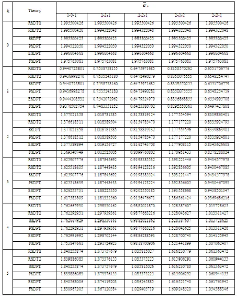
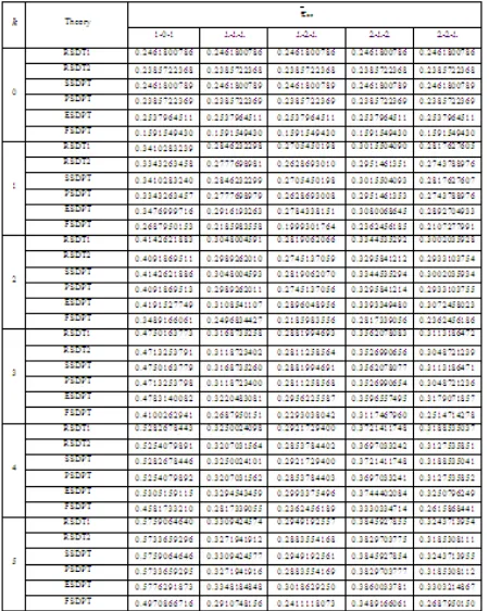
Table 2 contains the dimensionless center deflection w for an FG sandwich plate subjected to a sinusoidally distributed load. The deflections are considered for k= 0, 1, 2, 3, 4, and 5 and different types of sandwich plates. Table 2 shows that the effect of shear deformation is to increase the deflection. The difference between the shear deformation theories is insignificant for fully ceramic plates (k =0). It can be observed that the results obtained by the present refined theories RSDT1 and RSDT2 are identical to those of sinusoidal shear deformation plate theory (SSDPT) and parabolic shear deformation plate theory (PSDPT), respectively.
Manajemen dan Rekayasa Struktur C-83
aspect ratio a/b increases and this irrespective
of the type of the sandwich plate.
Table 4 lists values of axial stress σx for k= 0, 1, 2, 3, 4, and 5 and different types of sandwich plates. All theories (RSDT1, RSDT2, PSDPT, SSDPT, ESDPT and FSDPT) give the same axial stress σx for a fully ceramic plate (k= 0). In general, the axial stress increases with the volume fraction exponent k. However, the fully ceramic plates (k= 0) give the largest
axial stresses. It is to be noted that the CPT yields identical axial stresses as the FSDPT and so Table 4 lacks the results of CPT.
Table 5 shows similar results of transverse shear stress τxz for a FGM sandwich plate subjected to a sinusoidally distributed load. The results show that the transverse shear stresses as per the FSDPT may be indistinguishable. As the volume fraction exponent increases for FG plates, the shear stress will increase and the fully ceramic plates give the smallest shear stresses.
It can be observed that the results obtained by the present two models RSDT1 and RSDT2 are identical to those of the sinusoidal shear deformation plate theory (SSDPT) and the parabolic shear deformation plate theory (PSDPT), respectively. In general, the fully ceramic plates give the smallest deflections and shear stresses and the largest axial stresses. As the volume fraction exponent increases for FGM sandwich plates, the deflection, axial stress and shear stress will increase.
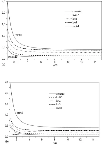
Fig. 3 shows the variation of the center deflection with side-to-thickness ratio for different types of FGM sandwich plates. The FGM plate deflection is between those of plates made of ceramic (Al2O3) and metal (Al). It can
be observed that, deflection of metal rich FGM plate is more when compared to ceramic rich plate. This can be accounted to the Young’s modulus of ceramic (Al2O3;
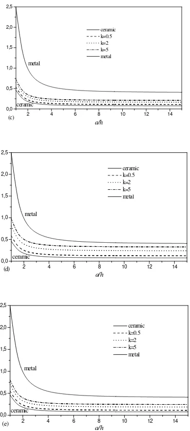
Fig 4 contains the plots of the axial stress
380 GPa) being
high when compared to that of metal (Al; 70 GPa).
x
σ
through-the-thickness of the FGM sandwich plates. The stresses are tensile above the mid-plane and compressive below the mid-mid-plane except for the nonsymmetric (2-2-1) FGM plate. The axial stress is continuous through the plate thickness. The results demonstrate a nonlinear variation of the axial stress through the plate thickness for FGM plates. It is important to observe that the maximum stress depends on the value of the volume fraction exponent kand the kind of the sandwich plate.
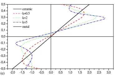
In Fig. 5 we have plotted the through-the-thickness distributions of the transverse shear stress τxz: The maximum value occurs at a point on the mid-plane of the plate and its magnitude for a FG plate is larger than that for a homogeneous (ceramic or metal) plate. Because of the non-symmetry of the (2-2-1) FGM plate, the maximum value of the transverse shear stress, τxz (Fig. 5d), occurs as discussed before at a point on the mid-plane of the plate.
It is important to observe that the stresses (Figs. 4 and 5) for a fully ceramic plate are the same as that for a fully metal plate. This is because the plate for these two cases is fully homogeneous and the stresses do not depend on the modulus of elasticity.
5. CONCLUSION
Manajemen dan Rekayasa Struktur C-84
and results were compared with previous other shear deformation theories. The developed theories give parabolic distribution of the transverse shear strains, and satisfy the zero traction boundary conditions on the surfaces of the plate without using shear correction factors. The accuracy and efficiency of the present theories has been demonstrated for static behavior of symmetric and non-symmetric functionally graded sandwich plates. All comparison studies demonstrated that the deflections and stresses obtained using the present two new shear deformation theories (with four unknowns) and other higher shear deformation theories such as PSDPT and SSDPT (with five unknowns) are almost identical. The extension of the present theory is also envisaged for general boundary conditions and plates of a more general shape. In conclusion, it can be said that the proposed theories RSDT1 and RSDT2 are accurate and simple in solving the static behaviors of symmetric and non-symmetric FGM sandwich plates.
REFERENCES
1. C.P. Wu, H.Y. Li, “An RMVT-based third-order shear deformation theory of multilayered functionally graded material plates.” Composite Structures, (2010).
2. M. Şimşek, “Fundamental frequency analysis of functionally graded beams by using different higher-order beam theories,” Nuclear Engineering and Design., 240, 697–705 (2010).
3. J. Ying, C.F. Lü, C. W. Lim, “3D thermoelasticity solutions for functionally graded thick plates,” J. Zhejiang Univ Sci A., 10(3), 327 – 336 (2009).
4. C. F. Lü, C. W. Lim, and W. Q. Chen, “Exact solutions for free vibrations of functionally graded thick plates on elastic foundations,” Mechanics of Advanced Materials and Structures. 16, 576 – 584 (2009).
5. C. F. Lü, C. W. Lim, and W. Q. Chen, “Semi-analytical analysis for multi-directional functionally graded plates: 3-D elasticity solutions,” Int. J. Numer. Meth. Engng, 79, 25–44 (2009).
6. C.P. Wu, S.E. Huang, “Three-dimensional solutions of functionally graded piezothermo-elastic shells and plates using a modified Pagano method.” Comput Mater Continua, 12, 251–82 (2009).
7. S.S.Vel and R.C. Batra, “Three-dimensional exact solution for the vibration of functionally graded rectangular plates,” J. Sound Vib., 272, 703–730 (2004).
8. E. Reissner, “The effect of transverse shear deformation on the bending of elastic plates,” J. Appl. Mech., 12, 69-77 (1945).
9. R. D. Mindlin, “Influence of rotatory inertia and shear on flexural motions of isotropic elastic plates,” J. Appl. Mech.,
18, 31-38 (1951).
10. E. Reissner, “On the theory of bending of elastic plates,” J. Math. Phys., 23, 184-191 (1944).
11. Y. Nath and K. K. Shukla, “Non-linear transient analysis of moderately thick laminated composite plates,” J. Sound Vibrat., 247, No. 3, 509-526 (2001). 12. S. Hui-Shen, “Nonlinear bending of
Manajemen dan Rekayasa Struktur C-85
13. T. Kant and K. Swaminathan, “Analytical solutions for the static analysis of laminated composite and sandwich plates based on a higher order refined theory,” Compos. Struct., 56, 329-344 (2002).
14. J. Sladek, V. Sladek, Ch. Hellmich and J. Eberhardsteiner, “Analysis of thick functionally graded plates by local integral equation method” Commun. Numer. Meth. Engng, 23, 733–754 (2007).
15. L. H. Donnel, “A theory for thick
plates,” in: Proc. Second U.S. Nat.
Congr. Appl. Mech., ASME Publ.
Univ. Michigan, Michigan (1955), pp.
369-373.
16. E. Reissner, “On the derivation of boundary conditions for plate theory,” in: Proc. Roy. Soc. London, 276, Ser. A, No. 1364, 178-186 (1963).
17. K. H. Lo, R. M. Christensen, and E. M. Wu, “A higher-order theory of plate deformation. Pt. 1: Homogeneous plates,” ASME J. Appl. Mech., 44, 663-668 (1977).
18. K. H. Lo, R. M. Christensen, and E. M. Wu, “A higher-order theory of plate deformation. Pt. 2: Laminated plates,” ASME J. Appl. Mech., 44, 669-676 (1977).
19. M. Levinson, “An accurate simple
theory of the statics and dynamics of
elastic plates,” Mech. Res.
Commun., No. 7, 343-350 (1980).
20. M. V. V. Murthy, An Improved
Transverse Shear Deformation
Theory for Laminated Anisotropic
Plates, NASA Techn. Paper (1981),
pp. 1-37.
21. J. N. Reddy, “A simple higher order theory for laminated composite plates,” J. Appl. Mech., 51, 745-752 (1984). 22. J. N. Reddy, “A refined nonlinear
theory of plates with transverse shear deformation,” Int. J. Solids Struct., 20,
No. 9, 881-896 (1984).
23. M. Touratier, “An efficient standard plate theory,” Int. J. Eng. Sci., 29, No. 8, 901-916 (1991).
24. K. P. Soldatos, “A transverse shear deformation theory for homogenous monoclinic plates,” Acta Mech., 94, Nos. 3-4, 1995-2200 (1992).
25. M. Karama, K. S. Afaq, and S. Mistou, “Mechanical behaviour of laminated composite beam by new multi-layered laminated composite structures model with transverse shear stress continuity,” Int. J. Solids Struct., 40, No. 6, 1525-1546 (2003).
26. A. J. M. Ferreira, C. M. C. Roque, and R. M. N. Jorge, “Analysis of composite plates by trigonometric shear deformation theory and multiquadrics,” Comput. Struct., 83, 225-2237 (2005). 27. A. Idlbi, M. Karama, and M. Touratier,
“Comparison of various laminated plate theories,” Compos. Struct., 37, No. 2, 173-184 (1997).
28. H. Altenbach, “Theories for laminated and sandwich plates,” Mech. Compos. Mater., 34, No. 3, 243-252 (1998). 29. J. N. Reddy and C. M. Wang, “An
Manajemen dan Rekayasa Struktur C-86
30. M.A. Benatta, I. Mechab, A. Tounsi, E.A. Adda Bedia, “Static analysis of functionally graded short beams including warping and shear deformation effects,“ Comput ational Materials Science, 44, 765–773 (2008). 31. B.O. Sallai, A. Tounsi, I. Mechab, B.M.
Bachir, M. Meradjah, E.A. Adda, “A theoretical analysis of flexional bending of Al/Al2O3 S-FGM thick beams,“ Computational Materials Science, 44, 1344–1350 (2009).
32. T. Mori, K. Tanaka, “Average stress in matrix and average elastic energy of materials with misfitting inclusions.” Acta Metall. 21, 571–574 (1973).
33. R. Hill, “A self-consistent mechanics of composite materials.” J Mech Phys Solids. 13, 213–222 (1965).
34. M. Chehel Amirani, S.M.R. Khalili, N. Nemati, “Free vibration analysis of sandwich beam with FG core using the element free Galerkin method.” Composite Structures. 90, 373–379 (2009).
35. S. Chi, and Y. Chung, “Mechanical behavior of functionally graded material plates under transverse load - Part I: Analysis.” Int. J. Sol. Struc. 43, 3657– 3674 (2006).
36. F. Delale, F. Erdogan F, “The crack problem for a nonhomogeneous plane.” Journal of Applied Mechanics 50, 609 (1983)
Figure. 1: Geometry of rectangular FGM sandwich plate with uniform thickness in rectangular Cartesian coordinates.
Figure. 2: The material variation along the thickness of the FGM sandwich plate
2 4 6 8 10 12 14
0,0 0,5 1,0 1,5 2,0 2,5
(a) ceramic
metal
ceramic k=0.5 k=2 k=5 metal
a/h
2 4 6 8 10 12 14
0,0 0,5 1,0 1,5 2,0 2,5
(b) ceramic
metal
ceramic k=0.5 k=2 k=5 metal
Manajemen dan Rekayasa Struktur C-87
2 4 6 8 10 12 14
0,0 0,5 1,0 1,5 2,0 2,5
ceramic metal
(c)
ceramic k=0.5 k=2 k=5 metal
a/h
2 4 6 8 10 12 14
0,0 0,5 1,0 1,5 2,0 2,5
(d) ceramic
metal
ceramic k=0.5 k=2 k=5 metal
a/h
2 4 6 8 10 12 14
0,0 0,5 1,0 1,5 2,0 2,5
ceramic metal
(e)
ceramic k=0.5 k=2 k=5 metal
a/h
Figure. 3: Dimensionless center deflection (w) as a function of side-to-thickness ratio (a/h) of an FGM sandwich plate for various values of k and different types of sandwich plates. (a) The (1-0-1) FGM sandwich plate. (b) The (1-1-1) FGM sandwich plate. (c) The (1-2-1) FGM sandwich plate. (d) The (2-1-2) FGM sandwich plate, (e) The (2-2-1) FGM sandwich plate.
-0,5 -0,4 -0,3 -0,2 -0,1 0,0 0,1 0,2 0,3 0,4 0,5
-2,0 -1,5 -1,0 -0,5 0,0 0,5 1,0 1,5 2,0
(a)
ceramic k=0.5 k=2 k=5 metal
-0,5 -0,4 -0,3 -0,2 -0,1 0,0 0,1 0,2 0,3 0,4 0,5
-2,5 -2,0 -1,5 -1,0 -0,5 0,0 0,5 1,0 1,5 2,0 2,5 (c)
ceramic k=0.5 k=2 k=5 metal
-0,5 -0,4 -0,3 -0,2 -0,1 0,0 0,1 0,2 0,3 0,4 0,5
-2,0 -1,5 -1,0 -0,5 0,0 0,5 1,0 1,5 2,0 (d)
ceramic k=0.5 k=2 k=5 metal
-0,5 -0,4 -0,3 -0,2 -0,1 0,0 0,1 0,2 0,3 0,4 0,5
-2,5 -2,0 -1,5 -1,0 -0,5 0,0 0,5 1,0 1,5 2,0 2,5
(b)
Manajemen dan Rekayasa Struktur C-88
-0,5 -0,4 -0,3 -0,2 -0,1 0,0 0,1 0,2 0,3 0,4 0,5
-2,0 -1,5 -1,0 -0,5 0,0 0,5 1,0 1,5 2,0 2,5 3,0
(e)
ceramic k=0.5 k=2 k=5 metal
Figure. 4: Variation of axial stress σx through the plate thickness for various values of k and different types of sandwich plates: (a) The (1-0-1) FGM sandwich plate. (b) The (1-1-(1-0-1) FGM sandwich plate. (c) The (1-2-1) FGM sandwich plate. (d) The (2-1-2) FGM sandwich plate, (e) The (2-2-1) FGM sandwich plate.
-0,5 -0,4 -0,3 -0,2 -0,1 0,0 0,1 0,2 0,3 0,4 0,5
0,00 0,05 0,10 0,15 0,20 0,25 0,30 0,35 0,40 0,45
(a)
ceramic k=1 k=2 metal
-0,5 -0,4 -0,3 -0,2 -0,1 0,0 0,1 0,2 0,3 0,4 0,5
0,00 0,05 0,10 0,15 0,20 0,25 0,30 0,35
(b)
ceramic k=1 k=2 metal
-0,5 -0,4 -0,3 -0,2 -0,1 0,0 0,1 0,2 0,3 0,4 0,5
0,00 0,05 0,10 0,15 0,20 0,25 0,30
(c)
ceramic k=1 k=2 metal
-0,5 -0,4 -0,3 -0,2 -0,1 0,0 0,1 0,2 0,3 0,4 0,5
0,00 0,05 0,10 0,15 0,20 0,25 0,30 0,35
(d)
ceramic k=1 k=2 metal
-0,5 -0,4 -0,3 -0,2 -0,1 0,0 0,1 0,2 0,3 0,4 0,5
0,00 0,05 0,10 0,15 0,20 0,25 0,30 0,35
(e)
ceramic k=1 k=2 metal
Figure. 5: Variation of transverse shear stress xz
τ through the plate thickness for various values of k and different types of sandwich plates: (a) The (1-0-1) FGM sandwich plate. (b) The (1-1-1) FGM sandwich plate. (c) The (1-2-1) FGM sandwich plate. (d) The (2-1-2) FGM sandwich plate, (e) The (2-2-1) FGM sandwich plate.
Table 1 Displacement models.
Model Theory Unknown function
CPT Classical plate theory 3 FSDPT First shear deformation plate
theory [8 – 10]
5 PSDPT Parabolic shear deformation
plate theory [21, 22]
5 SSDPT Sinusoidal shear deformation
plate theory [23]
5 HSDPT Hyperbolic shear deformation
plate theory [24]
5 ESDPT Exponential shear
deformation plate theory [25]
5 TSDPT Trigonometric shear
deformation plate theory [26]
5 RSDT1 Refined shear deformation
plate theory 1 (Present)
4 RSDT2 Refined shear deformation
plate theory 2 (Present)
Manajemen dan Rekayasa Struktur C-89
Table 2 Effects of volume fraction exponent on the dimensionless center deflections w of the different sandwich square plates.
Table 3 Effect of aspect ratio a/b on the dimensionless deflection of the FGM sandwich plates (k=2).
Manajemen dan Rekayasa Struktur C-90
Table 5 Effects of volume fraction exponent on the dimensionless transverse shear stress τxz of the FGM