Active Magnetic Bearings for Frictionless Rotating Machineries
Joga Dharma Setiawan
Abstract
Active magnetic bearing (AMB) systems can support a rotor without physical contact and enable users to precisely control rotor position and vibration as function of time or other parameters. These frictionless and programmable features have made AMB suitable to meeting the demand for higher speed, higher efficiency and reliability of rotating machineries in many industrial application including oil and gas production, power generation and energy conservation, clean manufacturing and transportation. This paper reviews the components and working principles of AMB, which requires basic understanding of rotordynamics, electromagnetisms, power electronics and control theories. Several configurations and applications of AMB are presented including design and cost issues. The capabilities of several major AMB world manufacturers are evaluated. The paper concludes with the summary of investigation topics at several leading AMB research centers. It is hoped that this paper can provide an up-to-date, brief and yet comprehensive introduction of the AMB technology for potential users and industrial communities in general.
Keywords : Control, magnetic bearing, magnetic levitation, rotordynamics
1. Introduction
Active magnetic bearings have several attractive advantages over conventional bearings because magnetic bearings levitate rotors and therefore have no physical contact with the spinning rotors. The use of magnetic bearings can significantly eliminate the frictions that usually exist in conventional bearings. Thus, in rotating systems, magnetic bearings can contribute to efficiency in energy, longer life, and the ability to operate at very high RPM. Other advantages include the elimination of mechanical maintenance of the bearing and lubrication, suitability for clean or vacuum room operation. The programmable feature typicaly includes the ability to adjust stiffness, damping, and periodic force as function of time or other parameters such as bearing temperature, RPM and angular acceleration.
Active magnetic bearings have been implemented in rotating systems in a variety of industrial applications. These applications include flywheel energy storages, momentum wheels, turbomachineries, precision
machineries, vacuum pumps, and medical devices.
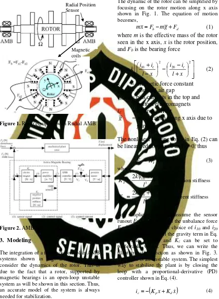
This paper reviews the components, working principles and characteristics of active magnetic bearing (AMB) systems. The most popular configuration as shown in Fig.1 is introduced [1-8] in which the AMB provides radial forces generated by four poles magnetic coils that are driven by power amplifiers operating in current mode.
2. AMB Components
Figure 1. Rotor equipped with Radial AMB
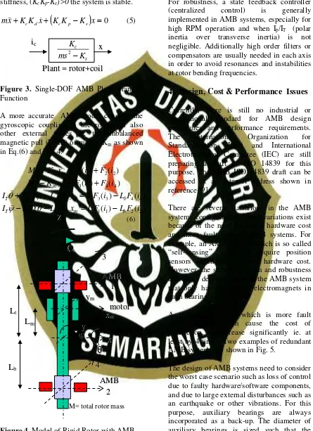
Figure 2. AMB system block diagram
3. Modeling
The integration of a feedback control in AMB systems shown in Fig. 2 must carefully consider the dynamics of the rotor. This is due to the fact that a rotor, supported by magnetic bearings is an open-loop unstable system as will be shown in this section. Thus, an accurate model of the system is always needed for stabilization.
The dynamic of the rotor can be simplified by focusing on the rotor motion along x axis shown in Fig. 1. The equation of motion becomes,
d
b mg F
F x
m&&= − +
(1)
where
m
is the effective mass of the rotor
seen in the x axis,
x
is the rotor position,
and
F
bis the bearing force
⎥
⎥
⎦
⎤
⎢
⎢
⎣
⎡
⎟
⎠
⎞
⎜
⎝
⎛
+
−
−
⎟
⎠
⎞
⎜
⎝
⎛
−
+
=
2 20 2 10
x
l
i
i
x
l
i
i
k
F
c cb
(2)
k
= magnetic force constant
l
= nominal air gap
i
10,i
20= bias currents in the top and
bottom electromagnets
i
c= control current
g
= acceleration along x axis due to
gravity
T
he nonlinear bearing force in Eq. (2) can
be linearized about
x
=0 and
i
c=0, thus
c c s
b
K
x
K
i
F
=
+
(3)
where
(
)
3 2 20 2 10
2
l
i
i
k
K
s=
+
; position stiffness(
)
2 2 20 2 10
2
l
i
i
k
K
c=
+
; current stiffnessFor simplicity, we can assume the sensor runout E=0 in Fig. 2 and the unbalance force Fd=0 in Eq. (1). Proper choice of
i
10 andi
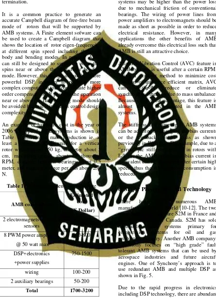
20 can be made to cancel the gravity term in Eq. (1) while Ks and and Kc can be set topreferrable values. Thus, we can write the plant transfer function as shown in Fig. 3. The plant is an unstable system. The simplest way to stabilize the plant is by closing the loop with a proportional-derivative (PD) controller shown in Eq. (4).
(
K x K x)
ic =− p + d& (4)
The closed-loop system dynamic then can be represented by Eq.(5). As long as the Magnetic
effective damping, KcKd>0 and the effective
Figure 3. Single-DOF AMB Plant Transfer Function
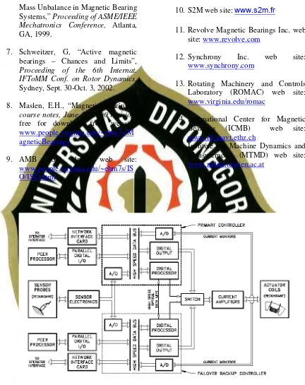
A more accurate AMB model consider the gyroscopic coupling in the rotor and also other external forces ie. the unbalanced magnetic pull (UMP) of motor, Km as shown
Figure 4. Model of Rigid Rotor with AMB
For robustness, a state feedback controller (centralized control) is generally implemented in AMB systems, especially for high RPM operation and when Ip/IT (polar inertia over transverse inertia) is not negligible. Additionally high order filters or compensators are usually needed in each axis in order to avoid resonances and instabilities at rotor bending frequencies.
4. Design, Cost & Performance Issues
Currently, there is still no industrial or international standard for AMB design procedures and performance requirements. The International Organization for Standardization (ISO) and International Electrotechnical Commitee (IEC) are still preparing a draft of ISO 14839 for this purpose. The AMB ISO 14839 draft can be accessed at an internet address shown in reference [9].
There are several variations in the AMB systems configuration. These variations exist because of the need for lower hardware cost and more fault tolerant AMB systems. For example, an AMB system which is so called “self-sensing”, does not require position sensors which means lower hardware cost. However, the stability margin and robustness can easily degrade. So does the AMB system that only has 3 poles of electromagnets in each bearing.
A redundant system which is more fault tolerant usually can cause the cost of production. to increase significantly ie. at least by 4 times. Two examples of redundant AMB systems are shown in Fig. 5.
The design of AMB systems need to consider the worst case scenario such as loss of control due to faulty hardware/software components, and due to large external disturbances such as an earthquake or other vibrations. For this purpose, auxiliary bearings are always incorporated as a back-up. The diameter of auxiliary bearings is sized such that the
i
electromagnets are well protected during the “crash” and during power start-up and termination.
It is a common practice to generate an accurate Campbell diagram of free-free beam mode of rotors that will be supported by AMB systems. A Finite element sofware can be used to create a Campbell diagram that shows the location of rotor eigen-frequencies at different spin speed including the rigid body and bending modes. In practice AMB can still be designed to support a rotor that spins near or above the first rotor bending mode. However, this design demands a more powerful DSP in order to perform more complex computation to accommodate higher order compensators. If possible the operation near or above the first bending mode should be avoided because it increases control design complexity and cost.
An example of hardware cost in the year of 2006 for typical AMB systems is shown in Table 1 assuming a mass production ie. at least a thousand AMB units for a vertical rotor with mass of 250 kg, diameter about 5 cm, maximum speed about 25 thousand RPM, distance between bearings about 0.5 meter, and maximum force per axis about 250 N.
Table 1. AMB components cost estimate
AMB components
Estimated cost
(US Dollar)
2 electromagnets+ position sensors
300-500
8 PWM power amplifiers,
@ 50 watt max
400-800
DSP+electronics
+power supplies
750-1500
wiring 100-200
2 auxiliary bearings 50-200
Total 1700-3200
It is worth noted that in some designs and applications, the total electrical loss of AMB systems may be higher than the power loss due to mechanical friction of conventional bearings. The wiring of power lines from power amplifiers to electromagnets should be made as short as possible in order to reduce electrical resistance. However, in many applications the other benefits of AMB already overcome this electrical loss such that AMB is still an attractive choice.
Adaptive Vibration Control (AVC) feature in AMB systems is useful after a certain RPM. Using a gradient method to minimize cost function of influence efficient matrix, AVC can “on-the-fly” reduce or eliminate synchronous vibration due to mass unbalance. Because of its great advantage, this feature is almost always incorporated in the AMB systems.
The stiffness and damping of AMB systems can be adjusted by changing the bias currents or the feedback control gains as shown previously in Eqs (3-5). For example, due to a “gyroscopic stiffening effect” in rotors with Ip/IT<1, the AMB stiffness or bias current in equivalent can be decreased after certain high speed; thus the AMB power consumption is reduced.
6. Major Players in AMB Technology
There have been numerous AMB manufacturer in the world [10-12]. The two most industrious ones are S2M in France and Revolve in Calgary, Canada. S2M has sold thousands AMB systems primary for compression systems for oil and gas production industry. Another AMB company, Synchrony focuses on “high grade” fault tolerant AMB systems that can be used by aerospace industries and future aircraft engines. One of Synchony’s approach is to use redundant AMB and multiple DSP as shown in Fig. 5.
of avenues for further research in AMB. Performance improvement, cost reduction, and additional design objectives within specific applications are some of the examples. In the recent years, researchers working on magnetic bearings have been aggressively focusing in areas such as (1) studies to utilize modern control methods including multi-variable controls, robust controls, non-linear controls, and adaptive controls in order to minimize rotor vibration; (2) studies of levitating more flexible rotors; (3) studies of self-sensing magnetic bearings; (4) studies on the joint use of magnetic bearings for levitation and motor-stators for rotation; (5) hybrid passive and AMB; and (5) studies on zero-power magnetic bearings using superconductor materials. Most of the above research topics are conducted at the three most notable AMB research and academic centers in the world [13-15]: (1) Rotating Machinery and Controls Laboratory (ROMAC) at the University of Virginia, Virginia, USA; (2) The International Center for Magnetic Bearings (ICMB) at The Institute of Robotics, ETH Zurich, Switzerland; and (3) Institute for Machine Dynamics and Measurements (MTMD), Viena University of Technology, Vienna, Austria.
6. Conclusions
The AMB technology has been briefly reviewed including its advantages, components, working principles, cost and performance. Some design and implementation issues have been also discussed. The authors believe that AMB systems are still relatively more expensive than conventional mechanical bearings; therefore the massive used of AMB in industries is still prohibitive despite of the many benefits offered. The AMB will still not completely replace conventional bearings in rotating machineries in the near future. However, AMB can find its place well in a limited volumes of high performance rotating machines.
References
1. Setiawan, J.D and R. Mukherjee, “Adaptive Compensation of Sensor Runout and Mass Unbalance in Magnetic Bearings without Changing Rotor Speed.” United States Patent number: 6,763,285 B2, July 13,2004.
2. Setiawan, J.D., R. Mukherjee, and E.H. Maslen, Synchronous Sensor Runout and Unbalance Compensation in Active Magnetic Bearings Using Bias Current Excitation, ASME Journal of Dynamics, Systems, Measurements and Controls, March 2002.
3. Setiawan, J.D., R. Mukherjee, and E.H. Maslen, Adaptive Compensation of Sensor Runout for Magnetic Bearings with Uncertain Parameters: Theory and Experiments, ASME Journal of Dynamics, Systems, Measurements and Controls, June 2000.
4. Setiawan, J.D., R. Mukherjee, and E.H. Maslen, “Variable Magnetic Stiffness Approach for Simultaneous Sensor Runout and Mass Unbalance Compensation in Magnetic Bearings,” Proceeding of the 7th International Symposium on Magnetic Bearings, Zurich, Switzerland, August 23-25, 2000.
5. Setiawan, J.D., R. Mukherjee, and E.H. Maslen, “Adaptive Compensation of Sensor Runout for Magnetic Bearings with Uncertain parameters: Theory and Experiments,” Proceeding of the 5th
International Symposium of Magnetic Suspension Technology, Santa Barbara, CA, 1999.
Mass Unbalance in Magnetic Bearing Systems,” Proceeding of ASME/IEEE Mechatronics Conference, Atlanta, GA, 1999.
7. Schweitzer, G, “Active magnetic bearings – Chances and Limits”, Proceeding of the 6th Internat. IFToMM Conf. on Rotor Dynamics, Sydney, Sept. 30-Oct. 3, 2002.
8. Maslen, E.H., “Magnetic Bearings”, course notes, June 5 , 2000 revision, free for download from website:
www.people.virginia.edu/~ehm7s/M agneticBearings
9. AMB ISO draft web site:
www.people.virginia.edu/~ehm7s/IS O/ISO.html
10. S2M web site: www.s2m.fr
11. Revolve Magnetic Bearings Inc. web site: www.revolve.com
12. Synchrony Inc. web site:
www.synchrony.com
13. Rotating Machinery and Controls Laboratory (ROMAC) web site:
www.virginia.edu/romac
14. International Center for Magnetic Bearings (ICMB) web site:
www.ifr.mavt.ethz.ch
15. Institute for Machine Dynamics and Measurements (MTMD) web site:
www.mdmt.tuwien.ac.at