Simulation of Compressible Gas-Liquid Flows in
Physical Cleaning Applications:
High-Speed Droplet Impact and Bubble Collapse
February 2019
Simulation of Compressible Gas-Liquid Flows in
Physical Cleaning Applications:
High-Speed Droplet Impact and Bubble Collapse
Thesis by
Tomoki Kondo
In Partial Fulfillment of the Requirements for the Degree of
Doctor of Philosophy in Engineering
Graduate School of Science and Technology
Keio University
©2019 Tomoki Kondo
ORCID: 0000-0003-2570-1324 All Rights Reserved
論文要旨
本論文では,液体ジェット洗浄および超音波洗浄に代表される流体物理洗浄技術の 洗浄メカニズム解明を目的として,高速液滴衝突および気泡崩壊に関する直接数値 解析を実行する.それらに付随する音響現象(キャビテーション,衝撃波伝ぱ)と 粘性現象(壁面せん断流の形成)を定量評価し,エロージョン(表面壊食)と付着粒 子除去性能の観点から考察する. 第一に,高速液滴衝突に付随するキャビテーションによるエロージョンの影響を 評価するための圧縮性・非粘性解析を行う.理論上,液滴内部を伝ぱする水撃衝撃波 は液滴界面(音響インピーダンス不連続面)との干渉により負圧領域を生じるため キャビテーションは発生し得るが,この現象を数値的に再現した研究例はない.キャ ビテーションの評価には相変化を考慮しない液滴衝突の数値解析から液相圧力履歴 を取得し,それをRayleigh–Plesset型方程式に入力することで,ある初期気泡核の運 動を解析する.すなわち,one-way-couplingに基づく数値解析を行う.解析の結果 キャビテーションの発生は数値的に確認され,そのキャビテーション気泡崩壊に伴 う音響放射は,衝突に伴う水撃圧を上回る可能性が示された. 第二に,高速液滴衝突が壁面上にもたらす水撃圧および壁面せん断流の形成を評 価する圧縮性・粘性解析を行う.ここでは乾燥壁面並びに液膜で覆われた壁面への衝 突を考慮し,乾燥壁面への衝突では壁面せん断流の形成を再現するため,三相が接触 する移動界面を正確に捉えるための滑り壁モデルを適用する.せん断流による粒子 はく離を評価するためには,粒子がせん断流から受ける表面応力トルクとファンデ ルワールス力のトルクの比較に基づき,壁面せん断応力分布を粒子はく離の可能性 を予測する無次元パラメータ分布へ写像する手法を提案する.本研究は液滴衝突に よる壁面せん断流形成が物理洗浄メカニズムに大きく寄与することを確認した.加 えて壁面上の液膜厚さに依存する水撃圧・壁面せん断応力の減衰率をモデル化した. 最後に,壁面近傍気泡の非球形崩壊に伴うマイクロジェットの形成および壁面せ ん断流の形成を評価する圧縮性・粘性解析を行う.対象として,単一気泡および気 泡間相互干渉を含む二気泡の崩壊を議論する.気泡崩壊では液滴衝突と異なり大幅 な気相体積変化が数値的な界面鈍りを助長するため,界面捕獲の移流方程式にこれ を修正するソース項を導入する.単一気泡崩壊の結果から,気泡壁面間距離の増加 に伴ってマイクロジェットは増速するが,壁面せん断応力はべき乗則に従って減衰 することを確認した.壁面に対して水平に位置する二気泡崩壊の結果では,気泡間 相互干渉によってマイクロジェットの衝突角が他方の気泡方向へ傾斜する作用が観 察され,その結果として壁面せん断応力の上昇は約1/10以下に著しく抑制されるこ とを確認した.Abstract
Spurred by the demand for cleaning techniques of low environmental impact, one favors physical cleaning that does not rely on any chemicals (e.g., liquid jet cleaning and ultra-sonic cleaning). In the present work, the cavitation accompanied by droplet impact and wall shear flow generated by droplet impact and cavitation bubble collapse near a rigid wall are simulated to understand their roles for surface erosion and cleaning contributions. Problems are modeled by solving compressible multicomponent Navier–Stokes (or Euler) equations and we solve a high-order accurate finite volume method that can capture both shocks and material interface.
Cavitation accompanied by high-speed droplet impact against a deformable wall is simulated to see whether the collapse is violent enough to occur surface erosion. The evolution of pressure waves in a single droplet to collide with a deformable wall at speed up to 110 m/s is simulated and the preexisting bubble nuclei (micron or submicron in
radii) show large growth to submilimeters based on a one-way coupling evaluation. It is also found, the radiated pressure from the cavitation bubble collapse can overwhelm the water-hammer pressure directly created by the impact.
Radially spreading wall shear flow generated by high-speed droplet impact is believed to achieve particle removal in liquid jet cleaning, but its mechanism is not well under-stood. We simulate high-speed droplet impact on a dry/wet rigid wall to investigate wall
shear flow as well as water hammer after the impact. The impact of a spherical water droplet (200µm in diameter) at velocity from 30 to 50 m/s against a dry/wet rigid wall are
considered. In the dry wall case, the strong wall shear appears near the moving contact line at the wetted surface. Once the wall is covered with the liquid film, the wall shear stress gets weaker as the film thickness increases; the similar trend holds for the water-hammer shock loading at the wall. Thereafter, we compute hydrodynamic force acting on small adherent particles in a one-way-coupling manner. The hydrodynamic force is estimated under Stokes’ assumption and compared to particle adhesion of van der Waals type, enabling us to derive a simple criterion of the particle removal.
Collapse of cavitation bubbles near a rigid wall leads to the formation of a high-speed reentrant microjet toward the surface which plays an important role in ultrasonic clean-ing. The jet impact accompanies radially spreading wall shear flow capable of removing contaminants from the surface, but the particle removal mechanism is not well understood due to the experimental challenges. We simulate the so-called Rayleigh bubble collapse (100µm in radius) near a no-slip, rigid wall to quantify the wall shear flow. Collapse of both single bubble and two bubbles are considered and the driving pressure ranges from 2
to 10 MPa. Our simulations show that generation of wall shear flow particularly after the jet impact. Lastly, the suppression effects on the wall shear stress due to the bubble-bubble interaction is clarified.
Acknowledgements
First and foremost, I would like to express my heartfeldt gratitude to my advisor, Prof. Keita Ando for his patient and enthusiastic guidance throughout the thesis project. Since I joined the laboratory, he was always supportive and gave me instructive advices which was essential for my growth and also my future career. I am very grateful for his gen-erosity that respects my interests and opinions. Again, I do appreciate his considerate mentorship over the past six years. I also thank my committee members, Prof. Akiko Matsuo, Prof. Koji Fukagata and Prof. Satoko Fujioka for their time and valuable advices towards my thesis.
I acknowledge Prof. Tim Colonius, Prof. Kazuki Maeda and Dr. Jomela Meng for their meticulous suggestions and advices during my three-month visit at California In-stitute of Technology in 2015. I also express my glatitude to Prof. Eric Johnsen, Dr. Shahaboddin Alahyari Beig, Dr. Mauro Rodriguez, Kazuya Murakami and Minki Kim for their kindness and very constructive discussions during my eight-month visit at Uni-versity of Michigan in 2017. Prof. Johnsen warmly welcomed me in his group and gave valuable comments and suggestions every week. I also particularly appreciate Shahab and Mauro for their time to discuss about state-of-the-art numerical schemes and to help my simulations on supercomputers. This collaborative research was especially precious for my study.
I appreciate weekly joint seminar with Prof. Shinnosuke Obi, Prof. Koji Fukagata and graduate students in their groups. Their constructive suggestions and comments were instructive and made great contributions to my study. It also helped me improve my academic presentation. I also appreciate Prof. Yoshiyuki Tagawa for having annual joint seminar and inter-laboratory collaborations. I am also grateful to Prof. Toshiyuki Sanada for his advices about studies of the droplet impact and the physical cleaning.
I truly wish to thank the past and present colleagues in Ando laboratory, Tatsuya Yamashita, Tatsuya Kobayashi, Takehiro Nakajima, Ryota Oguri, Masashi Sasaki, Eriko Shirota, Sosuke Fukui, Nobuyuki Nakamura, Risa Yamauchi, Kentaro Asano, Taisuke Sato, Yushi Yamakawa, Yoichiro Fukuchi, Atsuhide Inatomi, Yu Katano, Hiroki Kurahara and Ikumi Takemura for their warm encouragement and cooperation. Especially, I do appreciate Tatsuya Yamashita for wide-ranging discussions over the past six years. I am indebted for Tatsuya’s in-depth insights into bubble dynamics as an experimentalist. I was very happy to spent time together in the laboratory.
Last but not least, I would like to thank my family, who were always extraordinarily supportive all the time.
This work was supported in part by MEXT Grant-in-Aid for the Program for Leading Graduate Schools and JSPS KAKENHI Grant Number JP17J02211.
List of publication
(1) Articles on periodicals (related to thesis)
1. T. Kondo, S. A. Beig, E. Johnsen and K. Ando, “Simulation of shear flow generated by collapsing bubbles near a rigid wall,”In preparation.
2. T. Kondo and K. Ando, “Simulation of high-speed droplet impact against a dry/wet
rigid wall for understanding the mechanism of liquid jet cleaning,” Phys. Fluids, vol. 31, 013303, 2019.
3. T. Kondo and K. Ando, “One-way-coupling simulation of cavitation accompanied by high-speed droplet impact,”Phys. Fluids, vol. 28, 033303, 2016.
(2)
Articles on international conference proceedings (full-length
ar-ticles)
1. T. Kondo and K. Ando, “Compressible Navier–Stokes Simulation of High-Speed Droplet Impact Against Rigid Walls”, in Proc. of3rd International Symposium on Multiscale Multiphase Process Engineering (MMPE2017), Toyama, Japan, May, 2017.
2. T. Kondo and K. Ando, “Numerical study of cavitation and water-hammer erosion caused by high-speed droplet impact”, in Proc. of The 13th Asian International Conference on Fluid Machinery (AICFM13), Tokyo, Japan, September, 2017. 3. T. Kondo and K. Ando, “Numerical simulation of cavitation accompanied by
high-speed droplet impact”, in Proc. of 2nd International Symposium on Multiscale Multiphase Process Engineering (MMPE2015), Hamburg, Germany, September, 2014.
Contents
Abstract iii
Acknowledgment v
List of Publication vii
List of Figures xi
List of Tables xiv
Nomenclature xv
1 Introduction 1
1.1 Motivation . . . 1
1.2 Historical perspectives . . . 2
1.2.1 High-speed droplet impact . . . 2
1.2.2 Bubble collapse . . . 5
1.3 Objectives and contributions . . . 8
1.4 Organization of this thesis . . . 9
2 Cavitation accompanied by high-speed droplet impact 10 2.1 Introduction and outline . . . 10
2.2 Physical modeling . . . 10
2.2.1 Problem description . . . 10
2.2.2 Governing equations for the multi-component fluid flow . . . 12
2.2.3 Governing equation for the single bubble dynamics . . . 14
2.3 Numerical modeling . . . 17
2.3.1 Spatial discretization and temporal integration of the Euler flow simulation . . . 17
2.3.2 Temporal integration of the bubble dynamics simulation . . . 19
2.4 One-dimentional droplet impact . . . 19
2.5 High-speed cylindrical droplet impact . . . 20
2.6 Cavitation accompanied by the droplet impact . . . 26
3 High-speed droplet impact against a dry/wet rigid wall for understanding the
mechanism of liquid jet cleaning 29
3.1 Introduction and outline . . . 29
3.2 Physical modeling . . . 30
3.2.1 Problem description . . . 30
3.2.2 Governing equations for the multi-component fluid flow . . . 32
3.2.3 Partial velocity slip model . . . 36
3.2.4 Criterion for particle removal . . . 36
3.3 Numerical modeling . . . 40
3.3.1 Spatial discretization and temporal integration . . . 40
3.3.2 Computational domain and boundary treatment . . . 40
3.3.3 Verification: Stokes’ first problem . . . 41
3.4 High-speed droplet impact against a dry/wet wall . . . 47
3.5 Acoustic stage of the impact dynamics . . . 47
3.5.1 Water-hammer shock loading . . . 47
3.6 Hydrodynamic stage of the impact dynamics . . . 50
3.6.1 Side jetting . . . 50
3.6.2 Shear flow formation . . . 51
3.7 Particle removal judgement . . . 60
3.8 Summary . . . 63
4 Wall shear flow generated by bubbles collapsing near a rigid wall 65 4.1 Introduction and outline . . . 65
4.2 Physical modeling . . . 68
4.2.1 Problem description . . . 68
4.2.2 Governing equations for the multi-component fluid flow . . . 72
4.3 Numerical modeling . . . 75
4.3.1 Spatial discretization and temporal integration . . . 75
4.3.2 Computational domain . . . 77
4.3.3 Verification: Rayleigh collapse in free field . . . 77
4.4 Collapse of a single bubble near a rigid wall . . . 79
4.4.1 Speed of the microjet . . . 81
4.4.2 Shear flow formation . . . 83
4.4.3 Wall shear stress evolution . . . 88
4.5 Collapse of a bubble pair near a rigid wall . . . 89
4.5.1 Velocity and angle of the microjet . . . 92
4.5.2 Wall shear stress evolution . . . 96
4.6 Summary . . . 101
5 Concluding remarks 102 5.1 Conclusions . . . 102
5.2 Recommendations for future work . . . 104
5.2.2 Physical investigations of high-speed droplet impact and particle removal . . . 105 5.2.3 Physical investigations of bubble collapse . . . 107
Appendix
109
A Modeling of particle adhesion force by JKR theory 109 B Kinetic energy dissipation during the droplet impact 111
List of Figures
2.1 Computational setup of a cylindrical droplet and a deformable moving wall 12 2.2 Computational grid with the initial configuration of the droplet impact
problem . . . 17 2.3 Water-hammer pressures, simulated from the Euler flow simulation and
predicted from Heymann’s extended water-hammer equation . . . 20 2.4 (a) High-speed cylindrical droplet impact in the experiment of Fieldet al.
(1989). (b) Numerical Schlieren of the Euler flow simulation. . . 21 2.5 Pressure distributions at different times. . . 23 2.6 The experimental result att=10µs superimposed by the simulated
pres-sure contours. . . 23 2.7 (a) Pressure evolutions measured at Lagrangian pointsYϵ. (b) The
mini-mum pressure obtained from the simulations in (a). . . 24 2.8 Evolution of the radius of the cavitation bubble nucleated from a gas
bub-ble nucleus. . . 24 2.9 The pressure radiated from the cavitation bubble nucleated from a gas
bubble nucleus. . . 25 2.10 Maximum values in the radiated pressure at the wall as a function of
equi-librium nucleus radius. . . 25 3.1 Schematic of high-speed droplet impact against a wet rigid wall that
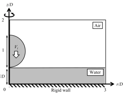
ac-companies water-hammer events, side jetting, and crown-like shape for-mation. . . 30 3.2 The initial configuration of a spherical water droplet impinging at velocity
Vi (at time t = 0) towards the wall (z = 0) covered with a water film of
thickness. . . 31 3.3 Schematic of the forces and torque acting on a spherical particle attached
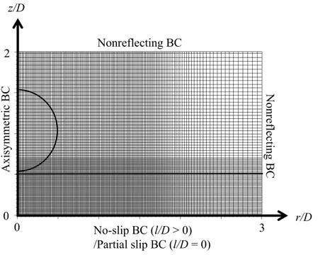
at a solid surface above which simple shear flow (of water) is created. . . 35 3.4 Computational grids (with every 20 grids presented) in which the initial
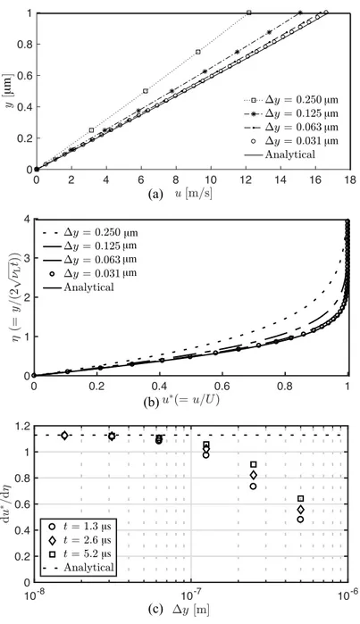
configuration of the water droplet and film location. . . 39 3.5 (a) Computations of (dimensional) near-wall velocity profiles. (b) The
nondimensional velocity profiles (at t = 2.67 µs) with varying the grid
spacing. (c) Convergence analysis of the computed velocity gradient at different dimensional times. . . 42
3.6 Snapshots of the droplet impact simulation at representative times for the case of (Vi, l/D)= (50 m/s, 0), plotting the distributions of the pressure,
the liquid velocity and the shear stress. . . 44 3.7 As Fig. 3.6, but with (Vi,l/D)=(50 m/s, 0.25). . . 45
3.8 As Fig. 3.6, but with (Vi,l/D)=(50 m/s, 0.5). . . 46
3.9 (a) Logarithmic plot of the maximum wall pressure. (b) Linear plot of the maximum wall pressure. . . 48 3.10 (a) Temporal evolution of the near-wall radial velocity profiles at r/D =
0.5. (b) Temporal evolution of the boundary layer thickness at different
radial positions near the impact point. . . 53 3.11 Spatiotemporal evolution of (a) the wall shear stress and (b) the wall
pres-sure. . . 54 3.12 (a) The (nominal) air-water interface profiles and the radial velocity
dis-tributions. (b) Distributions of the wall pressure and the pressure gradient. 55 3.13 As Fig. 3.12, but with (Vi,l/D)=(50 m/s, 0.5). . . 56
3.14 Distributions of the maximum wall shear stress encountered at each radial position for different film thickness and droplet impact velocity. . . 58 3.15 The maximum wall shear stress defined over both time and space as a
function of film thickness. . . 59 3.16 Spatiotemporal evolution of dimensionless parameter to judge particle
re-moval. . . 62 3.17 The particle removal area with varying film thickness and droplet impact
velocity. . . 63 4.1 The initial configuration and computational domain of (a) single spherical
air bubble in water and (b) a bubble pair. . . 67 4.2 Computational grids in which initial configuration of the single bubble
near a rigid wall for the case ofh/R0 = 1.1 is depicted by isosurface of
αL =αG= 0.5. . . 76
4.3 Temporal evolution of volume equivalent radius of a spherically collaps-ing bubble in water (∆p=5 MPa). . . 78
4.4 Snapshots of the bubble collapse near a rigid wall at representative times. 82 4.5 Maximum microjet velocity of the collapsing bubbles as a function of the
standoffdistance. . . 83 4.6 Temporal evolution of the near-wallz-velocity profiles. . . 84 4.7 (a) The (nominal) air-water interface profiles on the plane ofy = 0. (b)
Distributions of the wall pressure and the pressure gradient on the wall. . 85 4.8 Spatiotemporal evolution of the wall shear stress onz-axis (x= y=0) for
cases of∆p=5 MPa. . . 90
4.9 Distributions of the maximum wall shear stress encountered at each z -position on x=y= 0. . . 91
4.10 The maximum wall shear stress defined over both time and space as a function of the standoffdistance. . . 91
4.11 Snapshots of the collapse of two bubbles near a rigid wall at representative times for the case of (d/R0,h/R0,∆p)=(2.5, 1.1, 5 MPa). . . 93
4.12 As Fig. 4.11, but with (d/R0,h/R0,∆p)=(8.0, 1.1, 5 MPa). . . 94
4.13 Snapshots of the velocity magnitude and the jet angle . . . 95 4.14 Maximum microjet velocity of the collapsing bubbles and the jet angle as
a function of the distance between bubble pair . . . 96 4.15 Spatiotemporal evolution of the absolute wall shear stress on z-axis for
cases of (h/R0,∆p)=(1.1, 5 MPa). . . 98
4.16 Spatiotemporal evolution of the absolute wall shear stress on y-axis for cases of (h/R0,∆p)=(1.1, 5 MPa). . . 99
4.17 The maximum wall shear stress defined over both time and space as a function of distance between bubble pair. . . 100 B.1 The liquid-phase kinetic energy dissipation rate at representative times (i)
to (iii) forVi = 50 m/s and for different film thickness (i)l/D=0 and (ii)
List of Tables
2.1 Thermodynamic properties of air (ambient), water, 12 wt% gelatin (droplet), and Uranium/Rhodium alloy. . . 15
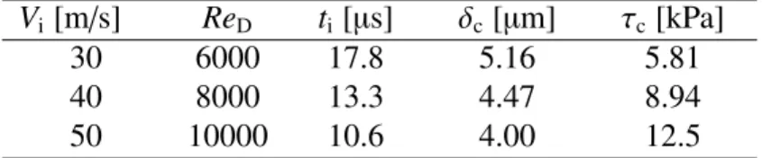
3.1 Physical properties of air (ambient) and water (droplet and film) used in the simulation. . . 35 3.2 Values of characteristic impact time ti, boundary layer thickness δc and
wall shear stress τc corresponding to different impact velocities Vi and
Reynolds numbersReD. . . 52
4.1 Simulated cases of parametric studies for driving pressures ∆p, standoff distanceshand inter-bubble distancesd. Single bubble collapse is noted as d = ∞, and 2.2 ≤ d < ∞ means collapse of a pair of the same-sized
bubbles . . . 66 4.2 Physical properties of water (ambient) and air (bubble) at 300 K used in
the simulation. . . 68 4.3 Values of characteristic velocityU, the characteristic water-hammer
pres-sure pwh, Rayleigh collapse time tc, microjet-based Reynolds numbers
corresponding to different driving pressures∆p for a bubble (100µm in radius) in water. . . 68 4.4 Values of characteristic boundary layer thicknessδc and wall shear stress
τc corresponding to different driving pressures∆pfor a bubble (100 µm
in radius) in water. . . 87 A.1 Material properties of PSL (particle) and quartz for the evaluation of
Nomenclature
BC Boundary condition CFL Courant–Friedrichs–Lewy HLL Harten–Lax–van Leer HLLC Harten–Lax–van Leer-Contact JKR Johnson–Kendall–Roberts NASG Noble-Able Stiffened gas PRE Particle Removal Efficiency PSL Polystylene latexRCA Radio Corporation of America VOF Volume of fluid
Chapter 1
Introduction
1.1 Motivation
Particulate contamination is one of the major issues in semiconductor manufacturing be-cause it is directly related to yielding loss. The target contamination is becoming smaller (sub-micron or even smaller) as the semiconductor devices become further miniaturized (Liet al., 1997). In this context, the central research topic is to develop a cleaning strat-egy that is highly efficient enough for ultra-precision manufacturing. Hereafter, cleaning is formally defined as removal of contaminant particles from material surfaces.
Historically, the popular cleaning method in industry is known as chemical immer-sion cleaning method. For instance, the Radio Corporation of America (RCA) cleaning method, one of the most popular immersion techniques, is composed of seven stages (Kern, 1990). Every stage requires immersion in solutions such as sulfuric acid, hy-drogen peroxide, and hyhy-drogen fluoride. Thereby, this classical type of static chemical immersion cleaning is time-consuming and its environmental impact is controversial. To deal with these issues, physical forces are incorporated in major recent cleaning processes to facilitate the particle removal efficiency (PRE) (Busnainaet al., 2002; Okorn-Schmidt
et al., 2013).
In physical cleaning based on hydrodynamic force, interaction between wall shear flow and adhered particles is believed to play an essential role (Henry & Minier, 2014).
Particle removal under simple shear flow of liquid or gas has previously been studied experimentally and analytically (Fanet al., 1997; Busnainaet al., 2002; Burdicket al., 2005; Zoeteweijet al., 2009). The mechanism of the particle removal can be classified into rolling, sliding, and lifting (to be recalled in Chapter 3). These previous studies suggest that the rolling mechanism arising from the torque induced by the hydrodynamic drag plays a dominant role in the particle removal and the rotatory motion of particles are also visualized by an image processing (Agudoet al., 2017b). In this sense, when it comes to facilitating the cleaning efficiency, it is essential to generate steep velocity gradients around attached particles. One of the promising methods is based on water jets that often involve fission into droplet fragments and collide with target surfaces (Watanabe et al., 2009; Erkan & Okamoto, 2014; Frommholdet al., 2015). The jet-based cleaning method has already become popular in precision processing and its performance improvement is one of the overarching goals. Furthermore, ultrasonic cleaning that uses the dynamics of acoustic cavitation bubbles in liquid batch is also known as high-efficient physical cleaning method (Gale & Busnaina, 1999; Kohli & Mittal, 2011; Yamashitaet al., 2018). As a particularly practical importance of ultrasonic cleaning, it is suitable for combination with chemical immersion.
In order to improve these types of physical cleaning, it is therefore imperative to fully understand two canonical multicomponent flow phenomena: high-speed droplet impact and bubble collapse. In what follows, these issues are addressed in further details.
1.2 Historical perspectives
1.2.1 High-speed droplet impact
High-speed droplet impact onto solid surfaces is relevant to a number of applications in industry. One of the classical examples is aircrafts whose wings are exposed to raindrop impact under their operation and eventually suffer from erosion due to the water-hammer
loading (Cook, 1928; Huanget al., 1973). More recently, such erosion becomes a tech-nical issue in ink-jet printing and physical cleaning based on liquid jets (Okorn-Schmidt
et al., 2013; Sanadaet al., 2008; Sanada & Watanabe, 2015; Tatekuraet al., 2015). One of the earliest theoretical studies is Heymann’s work that considers one-dimensional droplet impact at high speed where liquid compressibility comes into play (Heymann, 1969). Ex-tensions to the cases of deformable surfaces (Brunton & Rochester, 1979) and spherical droplets (Engel, 1955) were performed in the subsequent studies. Moreover, the impact of water droplets against solid walls has been studied experimentally in wide parameter space; the impact velocity ranges from 10−1m/s to 102m/s and the droplet diameter varies
between 10−5m and 10−2m (Visseret al., 2015). In these studies, both acoustic and
fluid-dynamic phenomena of the droplet impact have been widely studied (e.g., water hammer (Heymann, 1969; Dear & Field, 1988; Kennedy & Field, 2000; Halleret al., 2002; Sasaki
et al., 2016), cavitation (Fieldet al., 1989; Obreschkowet al., 2011), splashing (Yarin & Weiss, 1995; Wal et al., 2006; Thoroddsen et al., 2011; Guo & Lian, 2017; Banitabaei & Amirfazli, 2017; Boelens & de Pablo, 2018; Charalampous & Hardalupas, 2017), side jetting (Lesser, 1981; Weiss & Yarin, 1999; Halleret al., 2002) and rim instability (Reg-ulagaddaet al., 2017; Huanget al., 2018)).
It is interesting to note that recent studies suggest the potential role of cavitation within the impinging droplet in the issue of surface erosion (Field et al., 2012; Obreschkow
et al., 2011). Experimentally, cavitation accompanied by high-speed droplet impact was observed by Brunton & Camus (1970) and Field et al. (1989). The cavitation can be explained by acoustic impedance mismatch at droplet interfaces. When a water-hammer shock wave (arising from the impact) reflects at the distal interface of the droplet, the resulting tension wave can rupture the droplet, nucleating cavitation bubbles as illustrated by Obreschkow et al. (2011). Haller et al. (2002, 2003) simulated the impingement of compressible droplets against a rigid wall. Their simulation supports the formation of
such a tension wave within the droplet. Nevertheless, the contribution of such cavita-tion (and its collapse often followed by strong shock emission) to the erosion is not yet clarified.
Though the high-speed droplet impact has remained a central research topic over the past decades, further knowledge of its dynamics is still demanded in context of the phys-ical cleaning. To optimize the PRE of the jet-based cleaning, one can use monodisperse splay of micron-sized droplet train (Brennet al., 1997; Kimet al., 2003; Satoet al., 2011; Okorn-Schmidtet al., 2013; Visseret al., 2015). To evaluate the PRE quantitatively, vious researchers usually compared the number of contaminant particles between pre-and post-cleaned silicon wafers (Satoet al., 2011; Fernandoet al., 2011; Okorn-Schmidt
et al., 2013). However, this evaluation is insufficient to identify the mechanism of the particle removal and it is challenging to experimentally evaluate the wall shear flow de-velopment and particle removal. In this context, numerical approach will be an impor-tant tool to quantify the near-wall flow profiles and the shear-induced particle removal. There are some numerical studies about shear-induced particle removal in incompressible laminar flow (Agudo et al., 2017a), incompressible turbulent flow (Chen et al., 2018), compressible air jet (Songet al., 2014) and bubble collapse near a wall (Chahine et al., 2016). However, to our knowledge, wall shear flow formation during the droplet impact has not yet been simulated. Furthermore, to promote the efficiency of liquid jet cleaning, higher impact velocity is favored but may give rise to erosion of the cleaning surface due to water-hammer shock loading from the impact. Hence, to understand cleaning contribu-tions and erosion effects of high-speed droplet impact, both viscosity and compressibility of the fluids need to be accounted for.
1.2.2 Bubble collapse
Cavitation bubble collapse near solid boundaries is paid primal attention in a wide variety of applications because it may give rise to surface erosion. Such erosive effect is caused by the formation of a high-speed, reentrant microjet directed toward the wall surface during the bubble collapse phase (Plesset & Chapman, 1971; Lauterborn & Bolle, 1975; Shima & Tomita, 1981; Supponenet al., 2017). In hydraulic applications, many researchers have long studied bubble collapse in the context of cavitation erosion (Knapp, 1955; Arndt, 1981). More recently, the dynamics of acoustic cavitation bubbles have been of benefit in biomedicine (Brujan, 2011; Brennen, 2015), sonochemistry (Crum, 1994) and physical cleaning (Chahineet al., 2016; Yamashitaet al., 2018).
In the context of physical cleaning, the microjet impingement during the bubble col-lapse is an intriguing phenomenon because it may cause strong wall shear flow as seen in high-speed liquid jet cleaning (Watanabeet al., 2009; Erkan & Okamoto, 2014; Frommhold
et al., 2015). However, due to the experimental challenge to resolve the bubble dynamics and the resulting fluid flow, the cleaning mechanism is not well understood. We thus take a numerical approach for the quantitative investigations. In what follows, detailed litera-ture survey is provided for both experimental and numerical studies about the near-wall bubble collapse.
To experimentally investigate the bubble collapse near a wall, researchers mainly study its dynamics from a laser-induced cavitation bubble because it can highly control the position of cavitation inception by changing the focus location of a laser (Vogel & Lauterborn, 1988; Philipp & Lauterborn, 1998; Brujan et al., 2002). For understanding the surface erosion by the near-wall bubble collapse, impulsive pressure rise during the collapse is measured by Tomita & Shima (1986). To quantify the characteristics of the microjet velocity, a unified scaling law is proposed by Supponen et al. (2016) and that can examine the velocity of the microjet only by the stand-offdistance from the wall to
the bubble center without regard to various nonspherical collapse drivers (e.g., presence of the rigid surface, free surface, or pressure gradient). The near-wall fluid flow induced by the bubble collapse is visualized by Reuteret al.(2017a). Here, we note that bubble dynamics in underwater ultrasound is also studied from a laser-induced cavitation bubble for simplicity because it is challenging to control acoustic cavitation spatially and tempo-rally. In this context, the accompanying wall shear flow formation and its surface cleaning effect have been reported by few researchers. Ohlet al.(2006a) investigate the transition of wall-attached fluorescent particles during the collapse of a near-wall, laser-induced cavitation bubble to visualize the contribution of cavitation-induced wall shear flow to the cleaning. Thereafter, Dijkink & Ohl (2008) measure the wall shear stress at several spots, which arises from the laser-induced cavitation bubble, by means of a constant temperature anemometer. The other experiment of wall shear stress from cavitation bubble is carried out based on electrochemical microscopy by Reuter & Mettin (2018) and its result is fairly reasonable in comparison to the former experiment (Dijkink & Ohl, 2008). We note that both the above experiments only focus on the case of single bubble collapse while the cavitation is often occurred as a cluster near the target surface in ultrasonic cleaning. On the other hand, Kim & Kim (2014) visualize disruptive bubble collapse near a wall in ultrasonic field for understanding the surface damage in ultrasonic cleaning. Yamashita & Ando (2019 in press) investigate the ultrasound-induced reentrant microjet formation of a trapped bubble on a glass surface in oxygen-supersaturated water. This work also qualitatively reports the effect of the bubble-bubble interaction in the collapse of a bubble pair attached to the wall.
When it comes to simulation studies, Johnsen & Colonius (2009) perform Euler flow simulation to quantify the jet velocity and pressure emission of bubbles collapsing near a wall. Compressible Navier–Stokes simulation of bubble collapse near a wall that is designed by solution-adaptive, high-resolution scheme is performed by Beig & Johnsen
(2015). Thereby, the detailed characteristics of the jet velocity, pressure and temperature is quantified but near-wall flow profiles are beyond their scope (Beig, 2018; Beig et al., 2018). Their works also include the investigation of dynamics of a bubble pair in terms of microjet morphology. To understand the wall shear flow formation, Zenget al.(2018) numerically reproduce the experiment of Dijkink & Ohl (2008) by compressible Navier– Stokes simulation based on a volume of fluid (VOF) method. However, the simulated wall shear stress disagrees with the corresponding experiment. The difficulty is mainly related to the treatment of the computational grid that can sufficiently resolve the phys-ical viscosity. Since the viscous effects is only dominating in the vicinity of the wall in the bubble collapse simulation, fine grid spacing is only required locally near the wall. However, it tighten the Coulant–Friedrichs–Levi (CFL) condition and the simulation be-comes crucially time-consuming. Therefore, obtaining the correspondence between the experimental and numerical works are still challenging. In context of the simulation of the multiple-bubble dynamics, Tiwariet al.(2015) investigate the nonspherical collapses of respective bubbles in a near-wall bubble cluster but viscosity is neglected. On the other hand, the near-wall bubble collapse under ultrasound irradiation is simulated by Boyd & Becker (2018); Maet al.(2018); Qiuet al.(2018) and the reentrant microjet formation is reproduced like a laser-induced cavitation. Ochiai & Ishimoto (2017) numerically inves-tigate the multiple-bubble oscillations for megasonic cleaning applications to clarify the effects of bubble-bubble interactions in the bubble morphology and the wall pressure evo-lution. However, wall shear flow formation is beyond their scope and the spatial resolution is insufficient to resolve the near-wall viscous effect. Hence, to understand the cleaning mechanism, there is a need for further numerical investigations of the near-wall collapse of both the single and a pair of bubbles, which can sufficiently resolve the compressible viscous flow.
1.3 Objectives and contributions
Accordingly, to provide a more concrete insight for the improvement of physical cleaning, numerical investigations of high-speed droplet impact and bubble collapse near a wall are conducted. The main objective of this work is to understand compressible and viscous flow physics of these phenomena by direct numerical simulation in terms of the surface erosion by water hammer and the cleaning effect coming from the wall shear flow. More-over, coupled problems (e.g., cavitation during the droplet impact and particle removal in wall shear flow) are of great concern.
The main contributions of this thesis are summarized as follows:
• Correspondence between the current simulation and the previous experiment by Fieldet al.(1989) is obtained for cylindrical droplet impact and the cavitation oc-currence within the droplet.
• Cavitation threshold pressure is suggested under the specific cases of the droplet impact.
• In Navier–Stokes flow simulation, droplet impingement against a dry wall, which involves stress singularities on the moving contact line, is robustly reproduced by implementing a partial velocity slip condition based on molecular dynamics.
• Wall shear stress generated by the droplet impact is characterized as a function of the water film thickness covering the rigid wall initially.
• Nondimensional parameter for judging the possibility of particle removal is pro-posed as a function of wall shear stress, which evaluates the torque balances be-tween adherent force of van der Waals type and hydrodynamic surface torques from the wall shear flow.
• Wall shear stress generated by the cavitation bubble collapse is characterized as a function of the stand-offdistance from the bubble center to the wall in the case of single bubble.
• As an effect of bubble-bubble interaction, remarkable decaying of wall shear stress is observed in the cases of two-bubbles collapse and the effect of the length of the inter-bubble distance is evaluated.
1.4 Organization of this thesis
This thesis is organized as follows. In Chapter 2, cavitation accompanied by high-speed droplet impact is numerically investigated to clarify its role in surface erosion. Two-dimensional Euler flow simulation of the thin cylindrical gelatin droplet impact is first implemented to reproduce the previous experiment. The cavitation within the droplet is reproduced by solving the equation of Rayleigh–Plesset type in one-way coupling manner. Chapter 3 presents impingement of the spherical droplet is simulated for understanding the mechanism of liquid jet cleaning. Axisymmetric two-dimensional Navier–Stokes flow simulation is implemented to investigate the water-hammer pressure and wall shear flow generated by the droplet impact. As a treatment of the (no-slip) rigid wall, both dry and wet condition is considered. Given the flow profiles near the wall, particle removal is evaluated from the nondimensional parameter for the particle removal judgement. Lastly, in Chapter 4, cavitation bubble collapse is simulated to investigate the resultant wall shear flow formation. Three-dimensional Navier–Stokes flow simulation is implemented to re-produce the collapse of single bubble and two bubbles. Noted that these Chapters 2 to 4 include the sections of physical/numerical modeling respectively because these three
problems are simulated by different manners. Concluding remarks and suggestions for further study are stated in Chapter 5.
Chapter 2
Cavitation accompanied by high-speed
droplet impact
2.1 Introduction and outline
In this chapter, we numerically investigate the possible role of the collapse of cavitation bubbles accompanied by high-speed droplet impact as a source of erosion. For simplic-ity, we study the cavitation bubble dynamics in a one-way-coupling manner; the evolu-tion of pressure waves within the droplet to collide with a moving wall is obtained from multicomponent Euler flow simulation and is then substituted to a Rayleigh–Plesset-type equation to compute the dynamics of cavitation arising from small bubble nuclei that are supposed to exist inside the droplet. Particularly, we aim to see how large pressure ra-diation from the cavitation bubble collapse is in comparison to the initial water-hammer loading.
2.2 Physical modeling
2.2.1 Problem description
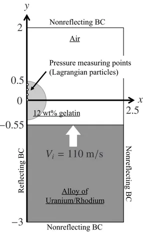
As a representative example, we numerically reproduce the experiment of Field et al.
(1989). In their experiment, a cylindrical, two-dimensional 12 wt% gelatin droplet fixed between transparent plates whose separation is 3 mm (much larger than cavitation bubbles
nucleated in between) is set into collision with a solid material moving at speed Vi =
110 m/s (see Fig. 2.1). Their claim is that the gelatin viscoelasticity does not play a role
in acoustic wave propagation inside the droplet. The diameter of the cylindrical droplet is 10 mm so that the Laplace pressure within the droplet is very small compared to the water-hammer pressure. The subsequent splash formation (where surface tention comes into play) is beyond our scope. Even though air entrapment between impinging droplets and a wall is reported for impact velocity up toO(10 m/s) (van Dam & Le Clerc, 2004; Li
& Thoroddsen, 2015; Liet al., 2015), it is ignored in our simulation with impact velocity of 110 m/s. Moreover, to be simple, we treat a deformable wall as a stiff fluid whose acoustic impedance is defined as the product of density and (longitudinal) speed of sound in the solid (Thompson, 1972; Sanadaet al., 2011).
After the impingement, the water-hammer shock wave reflects at the droplet interface as a tension wave due to acoustic impedance mismatch between the droplet and the ambi-ent air. Here, we explore the possibility of cavitation inception from micron/
submicron-sized gas bubble nuclei. Micron-submicron-sized gas bubbles exist naturally in tap water (O’Hern
et al., 1988; Mørch, 2015), so that the simulation will represent heterogeneous cavitation. On the other hand, unless contaminant gas bubbles are present in liquids, cavitation is ex-pected to occur homogeneously from submicron-sized voids that randomly appear among thermally fluctuating liquid molecules (Herbertet al., 2006; Caupin & Herbert, 2006). To numerically replicate homogeneous-like cavitation, we run Rayleigh–Plesset-type calcu-lations, starting from submicron-sized bubble nuclei, based on continuum assumptions (Maxwellet al., 2013; Tsudaet al., 2015). For simplicity, the volume fraction of nuclei and the subsequent cavitation bubbles is assumed to be so low that the pressure field in-side the droplet is not contaminated by the bubble dynamics; the bubble dynamics are then determined according to the pressure evolution (i.e., one-way coupling).
V
i=
110 m
/
s
x
y
2
.
5
Air! Alloy of Uranium/Rhodium 12 wt% gelatin !0
0
.
5
2
−
3
−
0
.
55
Pressure measuring points (Lagrangian particles)! Nonreflecting BC N onreflecting BC Nonreflecting BC Reflecting BC
Fig. 2.1:Computational setup of a cylindrical droplet and a deformable wall moving atVi(at time
t = 0). Because the problem is symmetric about theyaxis, the flow is simulated for x ≥ 0 only, imposing the reflecting boundary condition (BC) along theyaxis. Length scale is normalized by the droplet diameter.
2.2.2 Governing equations for the multi-component fluid flow
Accordingly, to capture the acoustic wave interaction in the high-speed droplet impact against a deformable wall, we solve multicomponent Euler equations modeled by five-equation formulation (Allaire et al., 2002; Perigaud & Saurel, 2005). Even though in-terfaces separating the three components are physically discontinuous in the sense of continuum mechanics, interface smearing is introduced in the simulation. Conceptually speaking, the mixture of the two neighbor components appears in numerically diffused interfaces. Here, mass conservation (Eqs. (2.1-a), (2.1-b) and (2.1-c)) is treated for gas, liquid and solid components separately, while momentum and energy conservation (Eqs.
(2.1-d), (2.1-e) and (2.1-f)) are formulated for the mixture. The numerically diffused interfaces are represented by volume fraction and advected by Eq. (2.1-g) and (2.1-h).
∂ ∂t ⎛ ⎜⎜⎜⎜⎜ ⎜⎜⎜⎜⎜ ⎜⎜⎜⎜⎜ ⎜⎜⎜⎜⎜ ⎜⎜⎜⎜⎜ ⎜⎜⎜⎜⎜ ⎜⎜⎜⎜⎝ αGρG αLρL αSρS ρu ρv E αG αL ⎞ ⎟⎟⎟⎟⎟ ⎟⎟⎟⎟⎟ ⎟⎟⎟⎟⎟ ⎟⎟⎟⎟⎟ ⎟⎟⎟⎟⎟ ⎟⎟⎟⎟⎟ ⎟⎟⎟⎟⎠ + ∂ ∂x ⎛ ⎜⎜⎜⎜⎜ ⎜⎜⎜⎜⎜ ⎜⎜⎜⎜⎜ ⎜⎜⎜⎜⎜ ⎜⎜⎜⎜⎜ ⎜⎜⎜⎜⎜ ⎜⎜⎜⎜⎝ αGρGu αLρLu αSρSu ρu2+p ρuv u(E+p) αGu αLu ⎞ ⎟⎟⎟⎟⎟ ⎟⎟⎟⎟⎟ ⎟⎟⎟⎟⎟ ⎟⎟⎟⎟⎟ ⎟⎟⎟⎟⎟ ⎟⎟⎟⎟⎟ ⎟⎟⎟⎟⎠ + ∂ ∂y ⎛ ⎜⎜⎜⎜⎜ ⎜⎜⎜⎜⎜ ⎜⎜⎜⎜⎜ ⎜⎜⎜⎜⎜ ⎜⎜⎜⎜⎜ ⎜⎜⎜⎜⎜ ⎜⎜⎜⎜⎝ αGρGv αLρLv αSρSv ρuv ρv2+p v(E+ p) αGv αLv ⎞ ⎟⎟⎟⎟⎟ ⎟⎟⎟⎟⎟ ⎟⎟⎟⎟⎟ ⎟⎟⎟⎟⎟ ⎟⎟⎟⎟⎟ ⎟⎟⎟⎟⎟ ⎟⎟⎟⎟⎠ = ⎛ ⎜⎜⎜⎜⎜ ⎜⎜⎜⎜⎜ ⎜⎜⎜⎜⎜ ⎜⎜⎜⎜⎜ ⎜⎜⎜⎜⎜ ⎜⎜⎜⎜⎜ ⎜⎜⎜⎜⎝ 0 0 0 0 0 0 αG∇·u αL∇·u ⎞ ⎟⎟⎟⎟⎟ ⎟⎟⎟⎟⎟ ⎟⎟⎟⎟⎟ ⎟⎟⎟⎟⎟ ⎟⎟⎟⎟⎟ ⎟⎟⎟⎟⎟ ⎟⎟⎟⎟⎠ . (a) (b) (c) (d) (e) (f) (g) (h) (2.1)
Here,αmis the volume fraction of componentmwherem=G, L and S stand, respectively, for the gas phase (air), liquid phase (gelatin) and solid phase (alloy),ρm is the density of componentm,ρis the mixture density (to be defined by Eq. (2.4)),uandvare velocities, respectively, in xandycoordinates, pis thermodynamic pressure,E is total energy (per unit volume), and∇·uis the divergence of the velocity vector field ((∂u/∂x)+(∂v/∂y)). Surface tension is neglected since capillary effects are expected to be less important in comparison to inertial effects in high-speed droplet impact Meng & Colonius (2015).
The system of Eq. (2.1) is closed by the stiffened gas equation of state:
p γ−1+ γP∞ γ−1 = E− 1 2ρ ' u2+v2(, (2.2)
whereγandP∞are thermodynamic constants for the mixture; the value ofγcontrols the material compressibility and P∞ corresponds to the tensile strength of liquids or solids due to inter-molecular cohesive force. Equation (2.2) can model perfect gases by setting γ = 1.4 (the ratio of specific heats for air) and P∞ = 0 (no cohesion between the gas
molecules). In the five-equation model, we need to introduce the following mixture rule to define quantities in the mixture:
αG+αL+αS= 1, (2.3)
φ= ' ρ γ P∞ (T, (2.5) φm= ' ρm γm P∞,m ( T , (2.6)
where φis a vector composed of respective mixture physical properties in Eq. (2.1) to
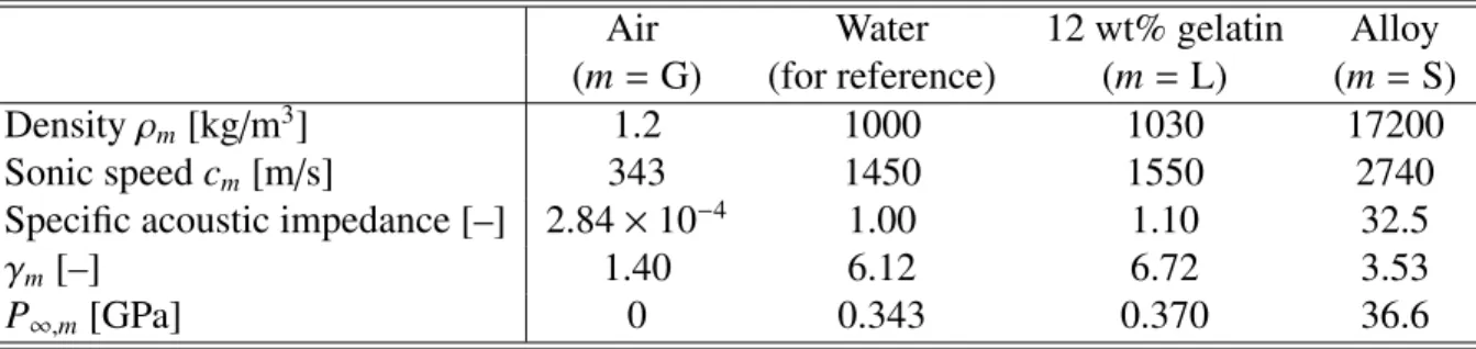
(2.2) andφmis a vector composed of respective physical properties of water (m= L), air (m = G) and an alloy (m = S). Table 2.1 summarizes the values ofγ and P∞ as well as other thermodynamic properties for materials of our concern (at standard temperature and pressure) (Gojaniet al., 2009; Coralic & Colonius, 2014; Saurel & Abgrall, 1999).
To record the pressure evolution within the droplet, Lagrangian fluid particles are initially set along they-axis and labeled asYϵ. This fluid particle position may represent
that of a preexisting gas-bubble nucleus whose size is assumed to be small enough to ignore slip with respect to its surrounding flow. The no-slip assumption will be more reasonable for gelatin gel droplets (as in Field et al. (1989); Shirota & Ando (2015)) whose elasticity is expected to hinder the slip of bubble nuclei relative to the surrounding material. We set the particles at the droplet center (ϵ = 0) and with the eccentricity
(normalized by the droplet diameter) from the droplet center selected at 0.1, 0.2, 0.25, and 0.3. During the Euler flow simulation, the particle is traced according to the flow and
the pressure it experiences is interpolated and recorded. The recorded pressure is used to determine the dynamics of a cavitation bubble to be nucleated atYϵ as explained in the
Section 2.2.3.
2.2.3 Governing equation for the single bubble dynamics
The dynamics of a spherical cavitation bubble nucleated at Yϵ are determined by the
Gilmore equation (Gilmore, 1952), an extended Rayleigh–Plesset equation that takes liq-uid compressibility into account:
RR¨ ) 1− CR˙ * + 3 2R˙2 ) 1− 3R˙C * =H ) 1+ R˙ C * + RH˙ C ) 1− CR˙ * . (2.7)
Table 2.1: Thermodynamic properties of air (ambient), water, 12 wt% gelatin (Gojani et al., 2009; Coralic & Colonius, 2014) (droplet), and Uranium/Rhodium alloy (Saurel & Abgrall, 1999) (wall). Acoustic impedance is normalized by the value of water.
Air Water 12 wt% gelatin Alloy
(m= G) (for reference) (m=L) (m=S)
Densityρm[kg/m3] 1.2 1000 1030 17200
Sonic speedcm[m/s] 343 1450 1550 2740
Specific acoustic impedance [–] 2.84×10⁻⁴ 1.00 1.10 32.5
γm[–] 1.40 6.12 6.72 3.53
P∞,m[GPa] 0 0.343 0.370 36.6
The dot denotes time derivative,Ris the bubble radius, andC andH are the sonic speed and the enthalpy of the droplet, respectively, at the bubble wall:
C = + , γ(p0+P∞) ρL0 )p L+P∞ p0+P∞ *γ−1 γ +(γ−1)H, (2.8) H = γ γ−1 p0+P∞ ρL0 ⎡ ⎢⎢⎢⎢⎢ ⎢⎣ )p bw+P∞ p0+P∞ *γ−1 γ − )p L+P∞ p0+P∞ *γ−1 γ ⎤ ⎥⎥⎥⎥⎥ ⎥⎦. (2.9)
Subscripts L and 0 mean quantities attributed to the liquid phase (droplet) and values at the equilibrium state (one atmosphere), respectively. The (far-field) liquid pressure,pL, is
given by the pressure recorded atYϵ in the Euler flow simulation (see Section 2.2.2), and
the bubble wall pressure (at the droplet side), pbw, is described by
pbw = pG+pv− 4µ ˙ R R − 2S R , (2.10)
where pGis the partial pressure of gas contents inside the bubble, pv is the saturated
vapor pressure (2.3 kPa at the undisturbed liquid temperature 20◦C due to the cold liquid
assumption (Prestonet al., 2007; Prosperettiet al., 1988)), and S is the surface tension. In this case, the gas pressure may be modeled by
pG= ) p0− pv+ 2RS 0 * 3R0 R 43κ , (2.11)
where R0 is the (equilibrium) radius of a gas bubble nucleus that is assumed to exist
at Yϵ and κ is a polytropic index; κ = 1 models isothermal gas behavior and κ = γ
corresponds to adiabatic behavior. For nonlinear bubble oscillations, we often rely on more sophisticated models of heat and mass transfer at the bubble wall (see for example Preston et al. (2007); Stricker et al. (2011); Warnez & Johnsen (2015)). In addition to the case of polytropic bubbles represented by Eq. (2.11), we consider dissipative effects of heat transfer inside the bubble and phase changes at the bubble wall based on the reduced-order model proposed by Preston et al.(2007). This model will be accurate for small bubbles whose Peclet numbers of heat and mass transfer are below or on the order of 10 (for details, see Prestonet al.(2007)); the model constraint is almost satisfied in our problem setup.
If the distancehfrom the bubble center to the wall is much larger than the bubble size (h(t)≫ R(t)), the bubble can be considered as a point source so that the radiated pressure is approximated by
pa = ρhL
'
2RR˙2+R2R¨(, (2.12)
where ˙Rand ¨Rare determined from integrating the Gilmore Eq. (2.7). The radiated acous-tic pressure pais to be compared to the water-hammer pressure obtained from the droplet
! "#! $#! !%#! !$#! !"#! ! "#! $#! & '
x
y
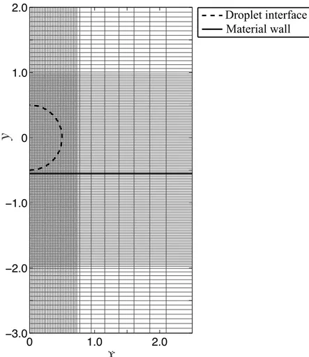
!"#$%&'()*'&"+,-& .,'&"),%()*'&"+,-&Material wall! Droplet interface!Fig. 2.2: Computational grid with the initial configuration of the droplet impact problem att=0. Gray line: computational grid (every 10 grid lines is presented). Blue and black lines: the nominal positions of numerically diffused material interfaces.
2.3 Numerical modeling
2.3.1 Spatial discretization and temporal integration of the Euler flow
simulation
The numerical method we use is based on the shock-interface capturing scheme proposed by Johnsen & Colonius (2006) and Coralic & Colonius (2014), which allows us to sta-bly simulate compressible flow involving both shocks and material interfaces. For spatial discretization, a third-order finite-volume weighted essentially nonoscillatory (WENO) scheme with the Harten–Lax–van Leer-Contact (HLLC) approximate Riemann solver
is adopted according to the previous droplet impact simulation by Meng & Colonius (2015). The component-wise WENO reconstruction is computed with primitive variables. The time integration is handled by a third-order total variation diminishing Runge–Kutta scheme (Gottlieb & Shu, 1998).
The numerical stability for the time integration is controlled by (dimensionless) Courant numberC, which is the ratio of physical and numerical wave speeds:
C =∆tmax i,j )c i,j+|ui,j| ∆xi , ci,j+|vi,j| ∆yj * , (2.13)
where the indicatoriand jdenote the numbers of computational cells inxandydirection, respectively. To stably capture the physical wave in simulations, it is necessary to satisfy the following Courant–Friedrichs–Lewy (CFL) condition:
0<C ≤ 1
N, (2.14)
where N stands for the number of spatial dimensions in the problem of concern. In this study, the time step is uniform with maximum Courant number set below 0.1.
The computational domain of the droplet impact is shown in Fig. 2.2. The grid is based on Cartesian coordinates. Since the flow is symmetric about theyaxis, we solve the prob-lem only forx≥0 by imposing the reflecting boundary conditions (Dadone & Grossman, 1994). While coarser grids are adopted away from the droplet in order to minimize spuri-ous wave reflection together with nonreflecting boundary conditions (Thompson, 1987), finer grids (with 200 grid points used for the initial diameter of the droplet) are used to re-solve the droplet. To avoid spurious oscillation at material interfaces, we use 8 grid points to diffuse interfaces in the initial configuration according to Johnsen & Colonius (2006). The nominal position of a numerically diffused interface is determined atαL = αG= 0.5
for the liquid/gas interface. We should note that air entrapment, which is reported
exper-imentally in low-speed droplet impact (van Dam & Le Clerc, 2004; Li & Thoroddsen, 2015; Liet al., 2015), cannot be observed because of the numerically diffused interfaces.
2.3.2 Temporal integration of the bubble dynamics simulation
Numerical integration of the Gilmore Eq. (2.7) is performed by ordinary differential equa-tion (ODE) solver ODE15s, which is provided by MATLAB and designed for stiff sys-tems, for stable and efficient calculations. As will be presented in Section 2.6, this method allows for resolving (numerically very stiff) violent collapse of cavitation bubbles.
2.4 One-dimentional droplet impact
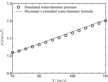
Before discussing the impact of a cylindrical droplet against the solid wall (alloy), we reduce it to a one-dimensional problem. That is, we may numerically replicate the initial stage of the droplet impact as a one-dimensional water column collision with the wall. To be simple, the ambient air between the two materials is excluded from the simulation. The numerical method applied in this reduced problem is the same as in simulating the two-dimensional droplet impact with very fine grids with sufficiently small CFL number. The impact speed of our concern is so high that nonlinearity would play a role in the acoustic wave propagation. In other words, it is inappropriate to use the celebrated water-hammer formula derived from linearized mass and momentum conservation laws. Heymann (1969) proposed the empirical formula to predict pressure generated from the high-speed impact: p=ρLcLVi ) 1+aVi cL * , (2.15)
where ρLcL is the acoustic impedance of the water (i.e., the product of densityρL and
sonic speedcL),Vi is the impact velocity, andais a constant empirically determined at 2
for water. Note that Heymann’s emprical formula reduces to the water-hammer formula by substitutinga=0. In Eq. (2.15), the solid is assumed to be rigid with infinite acoustic
impedance, which may be reasonable from the large acoustic impedance of the alloy (see Table 2.1).
10 50 100 150 0.9 1.0 1.1 1.2 1.3 Vi[m/s]
Simulated water-hammer pressure!
Heymann’s extended water-hammer formula!
p / ρl 0 cl0 Vi
Fig. 2.3: Water-hammer pressures, simulated from the Euler flow simulation and predicted from Heymann’s extended water-hammer Eq. (2.15), from one-dimensional impact of water and the solid wall (alloy) with varying the impact velocityVi. The pressurepis normalized byρLcLVi.
In Fig. 2.3, the simulated pressure with varying Vi is compared to the empirical
for-mula, Eq. (2.15). Here, the pressure is normalized by the (linear) water-hammer pressure ρLcLVi, so that its deviation from unity represents nonlinear effects. It turns out that the
simulation is well captured by the empirical formula. This simplified example suggests that nonlinear Euler flow simulations are essential to properly capture the dynamics of high-speed droplet impact.
2.5 High-speed cylindrical droplet impact
We numerically reproduce the cylindrical droplet (gelatin) impacted by the solid wall (al-loy) moving at Vi = 110 m/s. To see the evolution of acoustic waves arising from the
impact, numerical Schlieren images at different times are presented, together with the experimental observation from Field et al. (1989) (see Fig. 2.4). It follows that impor-tant features reported in the experiment including water-hammer shock propagation and the focusing of the reflected wave from the droplet interface are well reproduced in the
!! "! #! $! %! &! '! (! )! *!
(b)
!
(a)
!
Fig. 2.4: (a) High-speed cylindrical droplet impact in the experiment of Fieldet al.(1989). A 12 wt% gelatin droplet (10 mm in diameter) is impacted by a metal slider atVi = 110 m/s. Labels S and J mean shock and jet formation. A reflected tension wave (labeled R) is focused (labeled F), rupturing the gelatin (i.e., cavitation). The interframe between snapshots is 1µs. Reprinted
with permission from J. E. Fieldet al., ”The effects of target compliance on liquid drop impact,”
J. Appl. Phys., vol. 65, pp. 533–540. ©1989, AIP Publishing LLC. (b) Numerical Schlieren of the Euler flow simulation displayed at the same times as in (a).
simulation. The water-hammer shock propagates toward the distal side of the water-air interface of the droplet (frames a to h). Due to acoustic impedance mismatch, the shock is reflected as a tension wave (frame i), which is focused within the droplet (frame j). In the frame j of the experiment, it is reported that the gelatin was ruptured by the focused tension wave and a cloud of cavitation bubbles appeared in the focal spot.
To explain the cavitation observed in the experiment, we examine the evolution of the pressure field. Figure 2.5 shows the pressure distribution at selected times. From frames b to d, we observe the water-hammer shock propagation toward the distal side
of the droplet interface. The reflected wave is numerically confirmed as a tension wave (negative pressure) at frame e. Note that the liquid phase can support negative pressure (in absolute sense) owing to cohesion (represented by P∞ in Eq. (2.2)) between closely populated molecules, unless cavitation occurs.
It is instructive to make a rough estimate of the cavitation inception pressure in Fig. 2.4. For this purpose, we superimpose the simulated pressure contours onto the experi-ment att = 10µs; see Fig. 2.6. We see that the bubble nucleation can be found roughly
within the contour line of−20 MPa. That is, the gelatin gel can support its phase without rupturing on the way of approaching such a strong tension of about−20 MPa. The tensile strength (or equivalently a cavitation threshold) is close to the measurement of Maxwell
et al.(2013) in which cavitation was induced by the interaction between preexisting bub-bles and focused ultrasound pulses in gelatin phantoms and its threshold was measured using a hydrophone. It is also close to the cavitation threshold in distilled water (Herbert
et al., 2006). These observations imply that the cavitation in Fig. 2.4 might occur homo-geneously as contaminant bubble nuclei or particles that possibly exist in the medium are not activated under such a short tension state.
Finally, we report on the pressure recorded at Lagrangian markers set atYϵ inside the
droplet in Fig. 2.7. For the range of eccentricityϵ, every Lagrangian particle is exposed to large tension after 10µs (see Fig. 2.7 (a)). It follows that the most negative pressure (−33 MPa) is achieved at ϵ ≈ 0.25 (see Fig. 2.7 (b)). The recorded tension is far below the
Blake threshold pressure, which is determined from the quasistatic mechanical balance of gas bubble nuclei under tension (Brennen, 2014; Harkinet al., 1999; Ida, 2009) and is calculated at−5.6 MPa, for example, forR0 =10 nm. This clearly suggests the possibility
of having cavitation, even from nanobubble nuclei, whose dynamics will be explored based on Rayleigh–Plesset-type calculations as a next step.
30.0! 15.0! 0.0! -15.0! -30.0! [MPa]! (a) 0 µs! (b) 1.93 µs! (e) 9.98 µs! (d) 8.93 µs! (c) 5.95 µs! (f) 10.0 µs!
Fig. 2.5: Pressure distributions at different times. Solid lines represent material interfaces. Red and blue regions correspond to compression and tension, respectively.
30.0
!
15.0
!
0.0
!
-15.0
!
[MPa]
!
-30.0
!
Fig. 2.6: The experimental result att=10µs (see Fig. 2.4) superimposed by the simulated
pres-sure contours. Reprinted with permission from J. E. Fieldet al., ”The effects of target compliance on liquid drop impact,”J. Appl. Phys., vol. 65, pp. 533–540. Copyright 1989, AIP Publishing LLC.
! " #! #" $! !%! !$! ! $! %! & & t[µs] ϵ=0 ϵ=0.1 ϵ=0.2 ϵ=0.25 ϵ=0.3 p ( t ; Yϵ )[ M P a ] ! !"# !"$ !"$% !"& !'! !&! !$! !#! ! ϵ pmi n [MP a] (a) ! (b) !
Fig. 2.7: (a) Pressure evolutions measured at Lagrangian pointsYϵ. (b) The minimum pressure obtained from the simulations in (a).
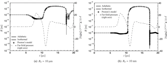
! " #! #" $! #!!## #!!#! #!!% #!!& #!!' #!!( #!!" #!!) #!!* ! " #! #" $!!)! !$! ! $! )! + + Isothermal! Adiabatic! Preston’s model! Far-field pressure (right axis)! !"" t[µs] p ( t ; Y ϵ = 0 . 25 )[ M P a ] (a) !R0=10µm R [m ] ! " #! #" $! #!!## #!!#! #!!% #!!& #!!' #!!( #!!" #!!) #!!* ! " #! #" $!!)! !$! ! $! )! + + Isothermal! Adiabatic! Preston’s model! Far-field pressure (right axis)! t[µs] p ( t ; Y ϵ = 0 . 25 )[ M P a ] !"" (b) !R0=10 nm R [m ]
Fig. 2.8: Evolution of the radius of the cavitation bubble nucleated from a gas bubble nucleus whose equilibrium radius R0 is (a) 10 µm and (b) 10 nm located at Yϵ=0.25. For reference, the far-field pressure that triggers the bubble dynamics is plotted by dotted lines scaled at the right vertical axis. Simulating the bubble’s thermal behavior is according to adiabatic and isothermal relations and the reduced order model of Prestonet al.(2007) that accounts for diffusive effects at the bubble wall.
! " #! #" $! !#! %! &! #%! ' ' t[µs] W all pressure p [MPa] ! Cavitation-induced radiation!
Euler flow simulation!
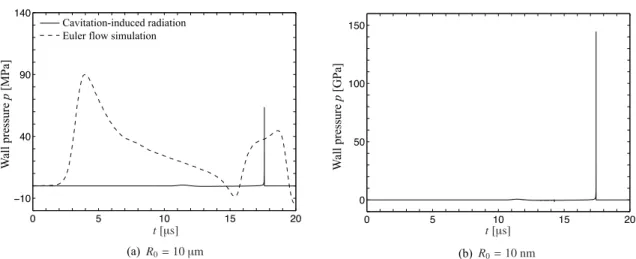
(a) !R0=10µm 0 5 10 15 20 0 50 100 150 t[µs] W all pressure p [GPa] ! (b) !R0=10 nm
Fig. 2.9: The pressure radiated from the cavitation bubble nucleated from a gas bubble nucleus whose equilibrium radius R0 is (a) 10 µm and (b) 10 nm located at Yϵ=0.25. For reference, the pressure measured at the wall from the Euler flow simulation is also plotted in (a). The bubble’s thermal behavior is evaluated by the reduced-order model of Prestonet al.(2007)
!"!# !"!$ !"!% !"!& !"!' !"" !"( !") !"& !"$ * * *************************+ W all pressure ! p / p at m Isothermal! Adiabatic! Preston’s model! R0 [m]
Fig. 2.10: Maximum values in the radiated pressure at the wall as a function of equilibrium nu-cleus radiusR0. Simulating the bubble’s thermal behavior is according to adiabatic and isothermal relations and the reduced-order model of Prestonet al.(2007).
2.6 Cavitation accompanied by the droplet impact
According to the one-way-coupling method (Section 2.3.2), we showed the possibility of having cavitation due to the wave interaction within the droplet. As a representative example, we consider cavitation bubble nucleation at Lagrangian position Yϵ=0.25 where
the most negative pressure is recorded (see Fig. 2.7). Gas bubble nuclei are assumed to behave either isothermally (κ = 1) or adiabatically (κ = γ) with their equilibrium size
selected at R0 = 10 µm (heterogeneous cavitation) or 10 nm (homogeneous-like
cavita-tion). For comparative purposes, we also examine diffusive effects on bubble dynamics by the reduced-order model of Prestonet al.(2007). The bubble dynamics corresponding to the far-field pressure at Yϵ=0.25 are summarized in Fig. 2.8 (a) for the heterogeneous
case (R0 = 10 µm) and (b) for the homogeneous-like case (R0 = 10 nm). It is found
that the nuclei exhibit rapid growth to submillimiters, supporting the visible observation of cavitation in the experiment of Fieldet al.(1989) While the collapse dynamics can be controlled by diffusive effects at the bubble wall (Preston et al., 2007), the growth phase is insensitive to the bubble’s thermal behavior as confirmed in Fig. 2.8, for the growth rate is simply determined from the inertia of the liquid surrounding the bubble whose pressure is essentially equal to the vapor pressure (Brennen, 2014). Also note that the growth dy-namics are rather insensitive to the equilibrium radius of bubble nuclei. Once the nucleus starts to grow, surface tension soon becomes less influential. As a result, the maximum bubble size is expected to be insensitive to the value of equilibriumR0 (Brennen, 2014;
Ceccio & Brennen, 1991). Under this situation, the maximum size is approximated by multiplying the Rayleigh growth velocity (Brennen, 2014) by a period of the tension state and turns out to be 310 µm in this example. This rough estimate leads to reasonable agreement with the simulation results in Fig. 2.8. Meanwhile, it is interesting to note that the rebound after the initial collapse is effectively eliminated in the case of the nanobub-ble nuclei for which the minimum radius of the collapsing bubnanobub-ble (about 0.1 nm in Fig.
2.8 (b)) is small enough to produce huge damping from viscosity and heat transfer at the bubble wall.
Finally, we examine pressure radiation from dynamics of the nucleated cavitation bub-bles in Fig. 2.9 (a) and (b), respectively, for the cases of R0 = 10 µm and 10 nm. The
pressure radiation due to the cavitation dynamics is recorded at the wall, h(t) measured fromY(t)ϵ=0.25, and plotted in this figure. For comparison, the water-hammer pressure at
the wall obtained from the Euler flow simulation is also plotted in Fig. 2.9 (a). It follows from the case ofR0 =10µm that the pressure radiation due to the first collapse (t≈ 17µs)
produces a large pressure impulse whose amplitude is comparable to the water hammer. On the contrary, the cavitation bubble collapse for R0 = 10 nm in Fig. 2.9 (b) emits a
far larger pressure impulse, but its extreme amplitude would violate the perfect gas law within the collapsing bubble that the Preston’s model employs.
In Fig. 2.10, the amplitude of the radiated pressure impulse due to the first collapse is plotted as a function ofR0(from 1 nm to 10µm). To see the effect of the bubble’s thermal
behavior, the results with adiabatic/isothermal bubbles and the Preston’s model are
pre-sented for eachR0. We first note that cavitation does not occur when R0 = 1 nm, which
is below the Blake critical radius and thus stable against the tension within the droplet. More importantly, the pressure radiation from the collapse becomes stronger as the nuclei size decreases. In other words, the cavitation bubble collapse becomes more violent as the ratio of the maximum bubble radius to the equilibrium nucleus radius increases. Even though the pressure amplitude is unreliable because of violating the perfect gas law, this trend gives us an important insight that homogeneous-like cavitation (with smaller bubble nuclei) is expected to produce more violent collapse that gives rise to more erosive im-pact on target materials. At the end, we should notice from Fig. 2.10 that the results with Preston’s model are close to those with adiabatic bubbles, meaning that violent bubble collapse is fast and thus adiabatic even at nanometer scales.
2.7 Summary
In summary, the possibility of cavitation accompanied by high-speed droplet impact against a deformable wall is investigated in one-way coupling manner; the presence of bubble nu-clei within the droplet is assumed and the bubble dynamics were determined according to the given pressure variation from the Euler flow simulation. The experiment of Field
et al. (1989) is reproduced for comparison in which cavitation is observed within the droplet colliding with a solid wall at speedVi = 110 m/s. The current simulation shows
good agreement from a viewpoint of acoustic wave propagation within the droplet (see Fig. 2.4 and 2.5): after the collision with the wall, water-hammer shock is propagated within the droplet and its reflection wave (at the distal side of the droplet surface against the wall) focuses at a particular point due to the curvature of the droplet surface. The agreement between the simulated and previously observed focus location of tension wave is excellent (see Fig. 2.6). Given the time history of pressure at Lagrangian markers within the droplet (see Fig. 2.7), one-way-coupling simulation is carried out based on the Rayleigh–Plesset-type calculation (with the equilibrium radius of bubble nuclei varied from submicrons to microns). It suggests the possibility of having cavitation caused by wave interaction within the droplet as shown in Fig. 2.8. More importantly, pressure radi-ation from the cavitradi-ation bubble collapse may overwhelm the initial water-hammer shock; this trend is emphasized for the case of homogeneous-like cavitation that arises from the growth of nanobubble nuclei (see Fig. 2.9 and 2.10). Therefore, such cavitation may be a noteworthy additional erosion factor in the problem of high-speed droplet impact.