IMPROV/N(; WATERMARK ROBUSTNESS AGAINST GEOMETRIC TRANSFORMATION ATTA(J( /wan 5ktyawan
IMPROVING WATERMARK ROBUSTNESS
AfiAIN.\'T fiEOMETRIC TRAN.\'FORMTION ATTACK
Iwan SetyawanAbstract
Tllis paper presents the challenges presented by geometric transformation attacks to watermark synchrotlization. Geometric distortion attacks can preYent proper detection
of the watermark by destroying the synchroruzation between the watermark and the
watermark detector. Tllis paper proposes two approaches to deal \Yith tllis problem.
The first approach remoyes strict spatial synchronization requirements of the
watermark. while the second approach enables watermark re-synchroruzation after a
geometric attack.
Keywortb:Digital watermarking. multimedia security. geometric transformation. "·atermark S)1Ichronization
1.
Introduction
One of the most difficult tasks faced by image and Yideo digital watermarking algorithm deYelopers is resistance to geometrical attacks. Geometric transformations may take
simple forms such as rotation. translation and scaling. They could also take much more
complex forms. for example rubber-sheet stretching. A famous example of the latter is the
StirMark software package that can perform a wide range of minor, unnoticeable geometrical
transformations on an image. including slight stretching. bending or shifting [l]. Another
example of geometrical attack is the Digital Cinema Attack [2]. The amount of geometric
transformation of the Yideo data is determined by numerous factors, e.g .. the position of the
camera with respect to the cinema screen. the (usually low) quality of the lenses in the camera
and the fact that the cinema screen itself is not perfectly flat. All these factors contribute to the complex combination of geometrical transformations applied to the recorded Yideo.
Geometric transformations do not actually remoYe the \Yatennark from the data. but
they work by exploiting the fact that most watermarking techniques rely on the
synchronization between the watermark and the watermark detector. If this synchronization is
destroyed. the detector can no longer correctly detect the presence of the watermark in the
Techne Jurnal Ilmiah Elektroteknika Vol. 8 No. 1 April2009 Hal31- 57
scheme relies on a high correlation Yalue to declare the presence of the watennark. If this
watermarked amage is now cropped by remoYing 5% of the pixels. the correlation Yalue
produced by the detector would be Yery low although most of the embedded noise pattern
itself is still present in the image.
Some approaches haYe been developed in the literature to deal \Yith attacks that
destroy the synchronization between the watermark and the detector. In this paper. we
propose two approaches designed to deal "-ith this synchronization problem. The first
approach we present is a new watermarking approach that is less sensith·e to synchronization.
The basic idea underlying our approach is to remoYe the requirement for strict
synchronization between the watermark and the detector. The second approach we present is
an approach that allows the synchronization of the watermark to be recoYered by inverting the
geometric transformation.
This paper is organized as follows. In Section 2, an oYerYiew of the existing
approaches to combat attacks that destroy the synchronization between the watermark and the
detector are discussed. In Section 3. we present a watermarking scheme that does not rely on
the rigid spatial synchronization between the watermark and the watermark detector. We
present the basic ideas. design considerations and our basic implementation of this idea. We
also present the e,·aluation of this basic implementation. In Section ·'-. we present the second
proposed approach to the synchronization problem. In this approach. we inYert the geometric
transformation to recoYer the spatial synchronization. We present the details of this approach
and the eyaJuation of its performance and in Section 5. we present our conclusions. As a final note. in this paper we use the term geometric tran4ormation to refer to the process l?( the attack and the term geometric distortion to refer to the results q(the attack.
2. Overview of the existing techniques to combat
geom etrictransformations
Existing techniques found m the literature to combat geometric transformations generally belong to the following categories of approaches. each \Vith its own strengths and weaknesses:
2.1. Performing the watermarking operation in a domain that is
invariant to geometric transformation
IMPROVING WATERMARK ROBUSTNESS AGAINST GEOMETRIC TRANSFORMATION ATTACK !wan Setyawan
transformed into this domain. the watermark is embedded in this domain and then the
data is transformed back to its original domain. On the detection side. the received
data is again transformed into the domain invariant to geometric transformation. A
watermark detection operation is then performed in this domain. An example of tllis
approach is given in [4]. In tllis scheme, the log-polar map domain is used. Tills
domain is invariant to rotation, translation and scaling operations. The advantage of
this approach is that if the correct im·ariant domain could be fotmd, then the
watermark would be resistant to the geometric transformations for "i1ich this domain
is innriant. In the previous example. the \Yatermark would be llighly resistant to
rotation, translation and scaling operations. However. finding a domain that would be
resistant to all possible geometrical transformations is very difficult. if at all possible.
2.2. Using re-synchronizeable watermarks.
The second category consists of approaches that embed a watermark that can be
re-s)llchronized after a geometrical transformation. One implementation of this
approach is to embed identifiable marker signals in the watermark \Vith certain
relative positions [5]. After an attack. the absolute positions of the markers are likely
to change. However. since the correct relative position is known. it is possible to
recover the original positions and thus イ・Mウセョ」ィイッョゥコ・@ the watermark. Alternatively,
the the synchronization points can also be derived from the invariant features of the
waten11arked data [6]. There is a security issue with this approach, namely that an
attacker can also detect and remove or jan1 the marker signal. To prevent this.
measures must be taken to llide or secure this signal [ 17. 18].
2.3.Reversing or compensating the distortions caused by the
geometrical transformation.
The third category consists of approaches that attempt to reverse or compensate
the effects of the geometrical transformation and restore the data to its original state.
One way to do tills is to compare the attacked data to the original undistorted data.
Based on tllis comparison. a restoration to the data's original state is then attempted. If
the restoration is successfuL then the probability of correctly detecting tl1e watermark
Techne JurnaJ IJmiah EJektroteknika Vol. 8 No. 1 April2009 Hal 31-57
original watermarked data An example of tlti.s technique is given m [7]. The
advantage of this approach. when it works. is obvious. The watermark detection
problem becomes vi1tually identical to the problem of detecting a watermark in
non-attacked data. The second approach we propose in this chapter belongs to this
category.
Another possible approach that is not widely used in tl1e literature. is
exhaustive search. In this approach. the watermark detector exhaustively searches the
space of all possible geometric transformations. Tins approach is not widely used
primarily due to the fact that the search space is very large. and thus the
computational cost of searching the correct geometric transformation \Vill be
unfeasibly high. Another. and more important. reason is that tllis approach can
produce an unacceptable rate of false positive in the watermark detection as sho\\11 in
[8].
All of the approaches discussed above have one common objective. nan1ely to
resist or recover from attacks that disturb the synchroruzation between the watermark
and the detector. These approaches aim to acllieve this objective by either making the
synchroruzation of the watermark robust (i.e .. hard to destroy) or making the
synclu-oruzation retrievable after an attack. However. all of these methods are still
dependent on the synclu-oruzation (i.e .. dependent on the proper phase information) in
order to function properly. The first approach we propose in this chapter deals \Yith
this problem trom a d1tlerent pomt of view. I.e .. by removmg the synchromzauon requirement.
3. Structured noise pattern watermarking
3.1. Basic idea
Our new watermarking approach is based on two new central ideas. First. the
watermark payload is embedded in the geometrical stmcture of the embedded
(invisible) watermark patch. An example of such a structure is the presence of a hole in the patch (representing watermark bit ''0'") or the absence of such a hole (representing watermark bit ··1 "). The choice of the geometrical stmcture of the
\vatennark patch to embed depends on wlti.ch watermark bit is to be embedded.
IMPROVING WATERMARK ROBUSTNESS AGAINST GEOMETRIC TRANSFORMATION ATTALl( !wan Setymran to such noise. Both the filter used to color the noise and the filter used to detect it depends on a secret key. Using tllis technique. we embed the information not in the phase of the watermark signal. but in its frequency distribution. Figure 1 presents an overvie'v of our approach.
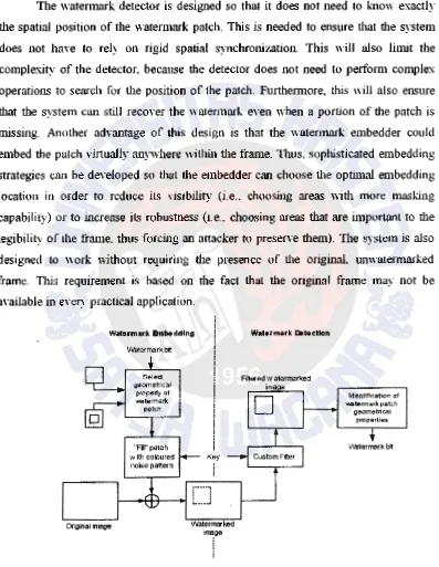
The watermark detector is designed so that it does not need to know exactly the spatial position of the watermark patch. This is needed to ensure that the system does not have to rely on rigid spatial synchronization. This will also limit the complexity of the detector. because the detector does not need to perform complex operations to search for the position of the patch. Furthermore. this will also ensure that the system can still recover the watermark even when a portion of the patch is missing. Another advantage of tllis design is that the \Yatermark embedder could embed the patch virtually anywhere \vitllin tl1e frame. Thus. sophisticated embedding strategies can be developed so tl1at the embedder can choose tl1e optimal embedding location in order to reduce its visibility (i.e., choosing areas witl1 more masking capability) or to increase its robustness (i.e .. choosing areas that are important to the legibility of the fran1e. tlms forcing an attacker to preserve tl1em). The system is also designed to work without requiring the presence of the originaL unwatermarked frame. This requirement is based on the fact that the original frame may not be available in every practical application.
Watermark Embedding
Original image
Watermark btt
''Filr' patch
w tth coloured
noise pattern
!
i
I
Key
Watermarked image
f
I
Watermark Detection
FiKered watermarked
ima e
D
watermark patch Identification of geometricalproperties
Watermark bK
[image:5.612.61.458.165.678.2]Techne JurnaJ Ilmiah Elektroteknika Vol. 8 No. 1 April2009 Hal31-57
From the previous discussion. the design challenges for our approach can be
classified into two different areas. The first one is directly related to the process of
patch embedding and detection. The basic objectives of this part of the design process
are as follows. In the first place. we have to design an identifiable pattern. i.e .. pattern
that could later be detected by the watermark detector. Thus. the pattern must possess
certain properties that can be picked up by the filter in the watermark detector.
Secondly. we have to keep the security of the pattern. i.e .. the generation and
detection of the patch should depend on a secret key. Without knowledge of this key
one should not be able to see the pattern (either completely or partially). Otherwise. a
potential attacker could generate a random key and then modify the pixel values of the
frame while obserdng the response of the detector to determine what level of
modification is sufficient to disable watermark detection. These two requirements is
contradictive. i.e., a highly structured pattern is easy to detect but also easy to guess.
while a random pattern is much more difficult to guess but is also hard to detect The
second area of the design challenge has more to do with the actual classification and
identification of the properties of the embedded pattern in order to recover the
watennark bit. This problem is very similar to the problems of linage segmentation
and pattern recognition. In this chapter. we concentrate on the first design challenge.
namely implementing the basic idea of being able to embed and detect a watermark
patch constructed using a colored noise pattern.
The キ。エ・イセョ。イォ@ embedder performs the following operation on the original
frame to embed a watermark patch
X, (i • .i)
=
X(i.j)+
y ·(P
0(x. yI
K)*
n(u. カIセ@=
X(i. j).X (i. j) E patch
otherwise (l)
In Equation ( 1 ). X,.{i ,/) represents the value of a pixel in the watermarked
frame. X(i ,/) represents the value of a pixel in the same position of the
non-watermarked frame. Po(x . .yiK) represents the filter (that depends on the key K) used to color the pseudo-random noise n(u.v) andy is a constant used to control the gain (and
thus the visibility) of the watermark patch Without loss of generality. we assume that
IMPROVING WATERMARK ROBUSTNESS AGAINST GEOMETRIC TRANSFORMATION ATTACK ]wan &tyawan
On the detection side. the received \Vatennarked frame is filtered using a
custom filter
PIU,iiK>.
thusX"f(i, .i)
=
セHクLケ@ 1 K) *X" (i, j) (2)Substituting X,..(i,i) with the expression from Equation (1). \Ve can rewrite Equation (2) as follows:
(3)
= l'1tx._rl Kl*X(i.j). othenYise
In Equations (2) and (3). X,.t(i,i) represents the value of a pixel of the filtered ''"atermarked image and P1(x.yiK) represents the filter in the ''"·atermark detector. again
depending on the same key. K. From Equation (3) we can observe that the response of the filtering operation for areas within the watermark patch is different from the
response of areas outside the watermark patch.
To detect the watermark patch. we calculate the local variances of the filtered
watermarked frame. expressed here in the Fourier domain. For simplicity. we drop the
K notation of the filters. The local variances of the watermarked frame within the
watermark patch can be expressed as follows:
(1'111:.
=
Tセ}@
}ゥセ\キャNHPャIゥ
RsLLNHHoャNHHNIャI、」ッQ、Ho[⦅@
+r:::.
I
fiPo(Ull.wl)I::IPl(C(.)l.wlfd(oldm;_• ·-Jf-ft -11-ff
(4)
On the other hand, in areas outside the watermark patch. the local variances
can be expressed as follows:
1 1T 1T
all/=
47Z"J
jャセ\キャLHPZZIQ
R@ s,,.(ca1.{01)dco,dco"-7(-tr
(5)
The detection of the embedded patch is based on the shift of the local variance
in areas within the \vatermark patch. as shown by the presence of the second term in
Equation (4). In order to get the best performance of the watermark detector. we
would have to do some optimization. From Equation (4) we can see that optimization
Techne Jurnal Ilmiah Elektroteknika Vol. 8 No. 1 Apri12009 Hal31- 57
optimization of approaches. The first one. C1[P1(w t.W2)]. is to try to minimize the first
term of Equation (4) while maximizing the second term. i.e ..
(6)
The second optimization approach is to minimize the ratio between the first
and the second terms ofEquation (4). i.e ..
., "' 11 11
イセセL[@
lDPo
((II I .((.1セ^iB@ iiセ@
(ml. (i)">1
2
droldw
セ@
(7) 」B{セH」MQQNHGQZ[I}@ = tnin
Fj ( ャセ|@ .l''..! .I
" 1t
I
iセセ@ (mi. (1)1)j' ,';',
((1.1' .ro1 )dw,dm2-1!-H
=tntn !J.((i\J•'::·•
JT ,y
ケ R」イLセ@
J JIPu
((0 1• (0 2
)I
21P,
((o1.ro2 ^iセ@ dm1lho セ@·-lf-R
To normalize the optimization problems. we assume (in addition to the
aforementioned Yariance of the colored noise) that the nriance of P1 is also equal to 1. These constraints are repeated belo\Y for conYenience.
1 " " '
4li
f
ヲェャセHャゥjiNイッZ[IェM
droid(i}:;=
1 -1f'-1T1 " " '
4" -Jf-71
f
jipイセH。^
Q
Nャゥj
R
IQM
dro1dliJ2=
1(8)
Let us first consider the first optimization approach. presented in Equation
(3.6). We can rewrite this equation and try to minimize the following:
(9)
1 1T " • '
471" ···1T-1f
J
JjP, (m1.(i)::)1-
S,, (m1.ro2 )dro1dm2-., ... 1f"
y
セZᄋ[@
J
f
QMpイセ@
(ro ,. m:;IQRQpセ@
(ro l.ro::f
d(i) ,dm 2IMPROVING WATERMARK ROBUSTNESS AGAINST GEOMETRIC TRANSFORMATION ATTACK /won Setymmn
Let us assume that pjH」オjNᆪオセI@
=
pjHMキjNMキセIN@ We can therefore rewrite Equation(9) as follo\\·s:
The solution of Equation (10) is therefore:
F;
(co1• 」ッセI]@ c5(co1• co).=0.
,vhen
s"'
(w1N」ッセIM
イセッMNセQp」LH」ッ
Q
N」ッIゥセ@
is minimumotherwise
(11)
Equation (11) means that the optimal P1 must be able to pick one single frequency pair (cu1.eo:2) where the original image data has relatively low energy
compared to the energy of the colored noise.
Let us now evaluate the second optimization approach, presented in Equation
(7).
First.
let us rewrite this Equation, dropping the factorsi
(sinceit is
obvious that larger )' will give a better detection) anda/
since it is assumed to be equal to 1.Furthermore. assuming that we have p
P
HュQ
NュQ
INセHュQ
NイッZIeセhN@ we will proceed tominimize piセᄋH」ッゥNwRI@ instead of PI(WI.W2). For notational simplicity. we will drop the
squares notation. Thus we have
1r 1T
J J
j^NH」ッQ
NHQIjsNMイH」ッQ
L」ッセI、」ッQ
、」ッZ@cZ{iセ@ ((I)• ,(I)J]
=min
.::::;:!:.::":!!..."-J -J
P0(co1.co:JJ;(co1.co)dco1dco:-·1(-JT
(12)
To evaluate Equation (12). we will use its 1-D discrete implementation for
purposes of simplicity. namely
[
:LF:
(/)8,.(/)Jc
[P. (/)]= •
-='=---.,...
: 1
IV,W
セpッ@
(l)J; (I) .oslsN
(13)Techne Jurnalll.miah Eleliroteknika Vol. 8 No. 1 April 2009 Hal 31 - 57
We haYe performed experiments \vith various Po(!) and S...,(l). and in all of
those experiments. the P1(1) solution that minimizes Equation (13) satisfies the
foHowing condition:
c: I I S.(l). . .
10r n
=
w 1ere -'-Is mmunumFe,(/) (14)
=0. otherwise
In Equation (14).
p/
1represents the nt11 element of P1(/) (0:::::; n :::::; N). In other
\vords. P1 only has a response at a single frequency. namely the frequency in "·hich the original data has relatiYely low energy compared to the colored noise energy.
We can thus draw a conclusion that both optimization approaches lead to the
same conclusion. namely that the optimal P1 must be able to pick one single spatial frequency. namely the frequency \Yhere the energy of the original image data is
relatiYely lmYer compared to the energy of the colored noise. However. if P1 is
implemented in this \vay, it would be Yery sensith·e to attack and small variations to
the data. Furthermore. we are interested in solutions that are spatially localized.
Therefore. our choice of frequency for P1 \vould depend heaYily on the spatial
location we are looking at. Since image data typically has low-pass behavior. ''"e can
conclude that the optimal frequencies to choose for P1 would be the high frequencies. Furthermore. to make the system more robust. we will design P1 so that it detects a
range of ヲイ・アオ・Qセ」ゥ・ウ@ (i.e .. the frequency range of Po) instead of just selecting one frequency. In other words. P1 should be constructed as a bandpass filter that can suppress the signal \vith frequencies outside the frequency range of Po. while passing a signal ""ithin tllis frequency range.
3.2. Basic practical implementation and evaluation
In this section. we present a basic practical implementation of the proposed watermarking approach and the evaluation of this basic implementation. We will first
describe the implementation of the watermark embedder and detector. then we will present
the results of our experiments. we perform our test by watermarking raw video sequences
with CIF resolution. In our experiments. we use Po and P 1 of size 8 x 8. Furthermore. the size
of the pseudo-random noise pattern (and hence. the size of the watermark patch) is chosen to
IMPROVING WATERMARK ROBUSTNES/;'AGA/NST GEOMETRIC TRANSFORMATION ATTACK /wan Setyawan
3.2.1. Watermark embedding
The watermark embedder follows the block diagram of the watermark embedding process presented in Figure 1. Since the video frames are treated as individual frames. the scheme could also be applied to still images. For the sake of simplicity. both still images and video fran1es will be referred to collectively as images. The watermark is embedded as a circular patch of structured noise pattern by modifying the luminance of the pixels of a chosen area of the image. In our experiment these areas are either chosen at random or detennined specifically by the user. In other \Yards. we have not used any of the sophisticated embedding strategies mentioned in the previous section. The choice of a disc as the shape of the patch is made for simplicity. although obviously other shapes can also be used. The modification of the value ofthe luminance is done according to Equation (la). We use y equals to 7. because in our experiments we found that y value of 7 or less gives an acceptable distortion to the watermarked image.
(a) (b)
Figure 2. The watermark patches:
(a) Patch representing ッNセN@ (b) Patch representing Os
Depending on the watermark bit to be embedded, either patch OA or Os is embedded. If watermark bit ··1 •· is to be embedded. then patch
0.
4 is chosen. [image:11.612.55.461.114.665.2]Techne Jurnal Ilmiah Elektroteknika Vol. 8 No. 1 April2009 Hal31- 57
watermark visibility and reliability of detection. Smaller sizes may be less conspicuous {for an equal y). but will make the patch harder to detect reliably. The ··hole'' (inner disc) of patch Os is put exactly in the middle of the outer disc in our experiments. Its size is user adjustable, and is expressed as a fraction of the area of the outer disc. The size of the inner disc will also determine the reliability of detection for patch Os. If the ratio is too big. then the "walls" would be too thin and the patch would be harder to detect reliably. On the other hand, if the ratio is too smalL the detection performance would also suffer because the two patches may become not easily distinguishable.
3.2.2. Watermark detection
The \vatermark detector follows the block diagram of the watermark detection process presented in Figure 1. As discussed in the previous section. the watermark detection procedure consists of two stages and we focus only on the first stage of this procedure. The first stage is a processing applied to the image that may contain a watermark This processing is done to "reveal" the watermark patch embedded in it. This stage is illustrated in Figure 3. In this Figure,
x;,
represents the received watermarked image. The custom filter Pt is a filter which depends on the san1e key as the one used to generate the filter during the watermark embedding procedw-e. The size of the kernel also has to be identical. X, ... 1 is the filtered version of the received watermarked image.セ}@
Thresholding
FitJtrc 3 Procc.\·s to rcl'crr! the 1t'atcrmork p:!tch
The processing of the watermarked image proceeds as follows. First. a copy of the received watermarked image is filtered using Pt. resulting in Xt.t: TIIen the local variances of this filtered image are calculated. The local variances calculation is done using a sliding window. In our experiments we choose a window with size n = 3.
IMPROVING WATERMARK ROBUSTNESS AGAINST GEOMETRIC TRANSFORMATION Afl'ACK
/wan Setyawan
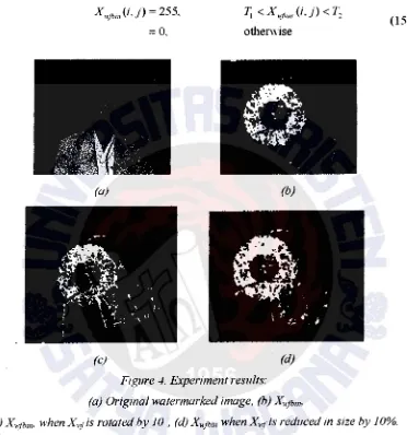
proceed to threshold X"lt,ti•ar and produce a binary image X.,:tbm which is the fmal output of tlus procedure and would become the input of the second stage of the watermark bit
detection process (identification of the geometrical properties of the watermark
patch). The thresholding is done as follows:
xu;tbm (i . ./)
=
255,=0.
(a)
(c)
T; < Xu:frar (i . ./) < tセ@
othenvise
(b)
[image:13.612.81.453.161.559.2](d)
Figure -1. Experiment results:
(a) Original watermarked image, (b) X.rtbm,
(15)
H」Nセ@ X"ltfbm· whenX.,tis rotated by 10·, (d) X.,:fbin whenX ... :ris reduced in size hy 10%.
In otl1er words, we designate the areas containing the watermark patch by assigning them a value of 255 (wlute) and the other areas are designated as
non-watermarked by assigning them the value 0 (black). The choice of the thresholds is a
trade-off bet\Yeen the probability of missed detection and probability of false alarm
(i.e .. designating an area outside the watermark area as watermarked). Choosing a
Techne Jurnal Ilmiah Elektroteknika Vol. 8 No. 1 April2009 Hal31- 57
designating an area within the watermark patch as not-watermarked) but reduce the probability of false alarm and vice versa.
In our experiments. we obsen·e that using P1 that is identical to Po does not
give a satisfactory result. In other words, the shift in the variances is too small to be detected and is masked by the original image signal. We therefore construct P 1 as a
convolution of a high-pass filter and Po. The high-pass filter is used to suppress the influence of the original image signal which has a primarily low-pass beltavior.
Optinlizing the detector using this high-pass filter gives an improved detection result. The result of our experiment is presented in Figure 4. Figure 4(a) shows the watermarked image before processing. Figure 4(b) shows X,,fbm with P1 constructed as
a convolution of a high-pass filter and Po. Figure 4(c) shows X'ltfbin when the
\vatennarked image is rotated by 10° and then cropped, and Figure 4(d) shows X.!tbm \vhen the watermarked image is resized by a factor of 1 0%. In all of these experiments. patch Os is embedded.
4. Complexity-scalable compensation of geometric transformations
Tllis section describes the second proposed approach to deal with the watermark synchroruzation problem. Tllis approach is based on a strategy for inverting the geometrical distortion . with the use of the original image. The term strategy refers to the choice of the transformation class, the degree of locality of the transformation and the method of estimating the parameters. given a set of correspondence vectors. These correspondence vectors can be generated by comparing the detected template and a reference template or. alternatively. by comparing the distot1ed image and a reference image (by using a motion vector field or by applying feature point detection in combination with point matching). An example of such a strategy is the application of an affine transform. first on a global scale. later on a more local scale [9]. Another example is the application of a translation (e.g. resulting from block matclling) in a coarse to fme approach [10].
I
JMPROVINO WATERMARK ROBUSTNESS AGAINST GEOMETRIC TRANSFORMATION ATTACK bran Setyawan
strategy is not the perfect registration of the image. but the recovery of the spatial
synchronization of the watermark.
4.1. Proposed strategy
The image registration problem can be formalized as follows. The spatial
transform is determined using corresponding points in a distorted image
Uk •.
M
and those from a reference image (i,; .. ik'). The corresponding points can be the result of point matching. block matching, etc. The proposed method uses an approximationmethod. i.e. given a set of N corresponding points. the function F is determined such that the corresponding points from the distorted and the reference images map as
closely as possible. In other words.
(. ' . ')
,k. ·.h ::::.F(·
1k ·A. )
k=L. ... N (16)Function F can then be used to register the distorted image.
The strategy consists of the consecutive estimation of a transform that is more
complex than the previous one. The one that fits best according to some criterion. is
chosen to be applied on the distorted image, prior to watermark detection.
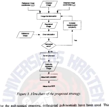
The scheme is shown schematically in Figure 5. Basically. the transformation
compleX'ity is progressively increased. minimising the Mean Square Error (MSE)
between the reference and registered image coordinates. hereafter to be called the
point error. Minimising the point error does not necessarily minimise the registration
error. i.e. the MSE between the pixel values of the registered image and reference
image. The transformation does not control \Vhat happens to points that lie in between
the N corresponding points used to compute the transform. Therefore. we base our choice of the optimally registered image on the registration error. We assume that
minimisation of the registration error yields an approximation of an optimal detection
Techne Jurnal Ilnuah Elektroteknika Vol. 8 No. 1 April2009 Hal31- 57
QQセQQQ@ Ht,l<. セ@ QQセQQQ@ d(.A "" . .A )
セ@ セュ、Hfセォᄋ@
_h).h
'·.h '))X"e
=
estimlX")where X and ..¥,, represent the unwatermarked and watermarked reference images. respectively.
X.rv
is the estimation of the watermarked reference imageX.,..
The function d( ·) denotes the MSE function. If the registration error has decreased. thecomplexity of the transformation is increased and the procedure is repeated.
Othenvise. the previous attempt is kept. The optimally registered image is used to
detect a watermark.
In the following section. an implementation using orthogonal polynomials for the
spatial transform is introduced. The procedure used to determine the corresponding
coordinates in the reference and distorted images is outlined in Section 3.4.4.
4.2.
Orthogonal polynomial mapping
We choose to use a polynomial mapping to implement the complexity-scalable
strategy presented in the previous section. The order of the polynomial mapping
determines the complexity of the spatial transformation and provides a logical ranking
in the degree of complexity in subsequent transformations. Conunonly used
transformation types such as rotation. scaling and affine transforms, are subclasses of
IMPROVING WATERMARK ROBUSTNESS AGAINST GEOMETRIC TRANSFORMATION ATTACK
!wan Setyawan
11\/atennark BER
r
-lncrease transfonnatlon
complexity
Yes
Figure 5. Flowchart l?lthe proposed strategy.
For the polynomial mapping. orthogonal ーッャセQQッョャNゥ。ャウ@ have been used. Tll.is
type of polynomial mapping has been used previously for image registration purposes
[ 11]. Due to the 011hogonality of these polynomials. the complexity of the transformation can be increased \\ithout the need for recalculation of the parameters
of lower order polynomials.
Equation ( 16) is split into two scalar functions. which are more convenient to
implement [ J 2]:
ik
ᄋセ@
f(ik ..i,J
jk Gセ@ g(i k, ./
,J
k=
L. ... N(18)
In the following. only the transformation
f
mentioned in Equation (18) will be [image:17.612.93.449.75.424.2]Techne Jurnal Ilmiah Elektroteknika Vol. 8 No. 1 April2009 Hal31- 57
A set of M polynomials
{セ@
v
.
.i
),
ーセ@
v .
.i
), ... ,
P_\[(i,
.f)
(19)is orthogonal oYer points (xk, J'k). k = 1 ... N if the following relation holds between them:
.v
""'P (· · )'0 (· · ) -0
£... X 1k• .h :t _1 /k• .h - x,y=1,2,3 ... M x:;t:y (20)
The function.fusing polynomials becomes:
.\[
ヲセNェZ。
Q
NPQ@
••••• a.u)= iGN。⦅LNpカセᄋNゥI@ (21).l·=i
The number of matched points. N. should be much larger than the number of parameters to be estimated. M. If M is equal to the number of non-collinear points. these points will map exactly on top of each other. If M << N . there is some robustness to overcome mismatches and to increase spatial accuracy. The exact number of non-comnear points that is needed to yield a good registration result depends on the spatial accuracy of the used points and the presence of mismatches.
Using a set of M linearly independent functions
hl
v
.
.J),h2 (i,.J), ..
.
,h.\1
v
.
.J)
(22)IMPROVING WATERMARK ROBU..\'TNESS AGAINST GEOMETRIC TRANSFORMATION ATTACK !wan Setyawan
セHゥN@ j
)==
W11h1(i .
./)
セHゥ@
. .i)=
キ
RQ
セHゥN@
J)+
w-:.2h;.(i.J)
(23)
:\1-1
{セ
Q@
(i.
j)
=
L
キBセjjL@
(i. j)
+
w,,L\1
/1.11(i.
j)
y=l
To calculate the mapping/
w.,!.
and a.,. haYe to be determined. We compute theparameters
w,.,.
(x=
L ... M: y = L ... x) by setting the W.Yi Yalues to W.Yi = 1 for all x.and applying the least-squares criterion and the orthogonal-ization property to the
polynomials [ 12]. Tllis results in:
w.,. = .\" k-1 x=2 ... M (24)
ャZセHゥォN@
jk
)h,(ik.
jk)
k=l
jV
LP,.(ik,jk )h,.(ik,jk)
11',.
=
-111,., . .:!.;k::!.l_,\:;'-.
L[P,(ik,j")f
x=2, ... ,M
y=2, ... ,M -1 (25)
ォセj@
Thls result is used to estimate the parameters of function fin Equation (21)
using the follo\\·ing relation:
N
'L>k
'P,Vk-JJ
a,. = セォMセセLQ@
-L:[P..Vk-.ik)r
(26)
k=l
Techne Jurnal Ilmiah Elektroteknika Vol. 8 No. 1 April2009 Hal31- 57
(27)
Thus. the complexity of the spatial transform can be iteratively increased. by
increasing the order of the desired mapping
f
and evaluating all polynomials havingequal or smaller order. Thus, there is no preference for the i orj directions.
Performing least squares with orthogonal polynomials offers several
advantages over ordinary pol)nomials. First, closed-form expressions for the
calculation of parameters are available (Equations 25 - 27). eliminating the need to
solve a system of equations. Further. the parameters of lo,ver order terms do not l1ave
to be recalculated when a higher order polynomial mapping is deemed necessary.
Distortions that actually are pol)nomial n1appings themseh·es are likely to be
easily corrected. Some (non-linear) distortions tl1at can be effectively approached by
polynomial expansion are likely to be corrected effectively. given enough correct
matching points. On a global scale. highly non-linear distortions are expected not to
be corrected effectively. yielding a high BER after distortion correction.
4.3. Implementation and results
In the test setting, a multibit watermark (144 bits) is embedded in a gray scale
image. The \Yatennarking bits are embedded in the spatial donlain by adding
pseudo-noise patterns to image pixel blocks [3]. Tllis scheme is chosen because it is quite
sensiti,·e to geometrical distortion and therefore gives a good indication of the
performance of the distortion compensation.
In [13] and [14]. se,·eral feature point detectors are evaluated. Both select the
Stephens and Harris corner detector [15]. among others because it preserves most
feature points after geometrical distortion. The detector used has pixel accuracy in the
j
IMPROVING WATERMARKROBUSTNESSAGAJNSTGEOMETRIC TRANS FORMA TJON ATTACK !won Setymmn
4.3.1. Perfect match experiments results
In our controlled experiments. the feature points were matched artificially.
fully exploiting the knowledge of the applied distortion. resulting in a pet:fect matL'h.
By perfect match we mean that no matching errors are present. In the case of feature
points. only points that are detected in both the reference and the distorted image are
used. This was done to assess the potential of the strategy in a mismatch-free
enYironment. In the image registration experiments. three distributions of
corresponding points are eYaluated:
1. Uniformly distributed grid markers (625):
2. A large number of matched points from a Harris detector (350-500):
3. A smaller number of matched points from a Harris detector (50-100):
Grid markers are artificially created markers. not present in the in1age. that
undergo the same distortion as the image. Besides simple RST. affine. ーイセェ・」エゥy・@ and
bilinear transforms. seYeral bending transformations haYe been applied. including
sinusoidal bending. the barrel and pincushion transform [12].
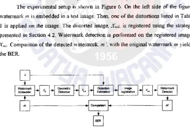
The experimental setup is sho\\n in Figure 6. On the left side of the figure.
watermark m is embedded in a test image. Then. one of the distortions listed in Table
1 is applied on the image. The distorted i.tnage.
X ..
J. is registered using the strategypresented in Section 4.2. Watermark detection is performed on the registered image.
xLNセN@ Comparison of the detected watermark. m ·. with the original watermark m yields the BER.
セMMMMMMMMMMMMMMMMセセセセュセセセMMMMMMMMMMMMMMセ@
[image:21.612.58.445.391.651.2]8
Figure 6. Image registration scheme
51
Techne Jurnalllmiah Elektroteknika Vol. 8 No. 1 April2009 Hal31 -57
In the estimation and correction block. feature points (or grid markers) are
extracted f'i"om both the distorted and the reference in1age. Exploiting the knowledge
of the applied distortion. the match behveen the corresponding points is generated.
The distorted image is registered using the strategy described in earlier sections.
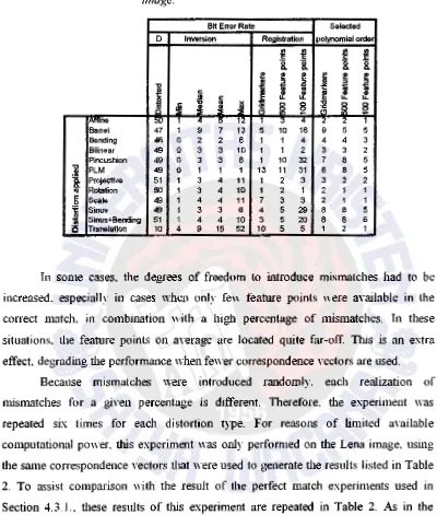
The results of tlns experiment for a Lena image are shown in Table l. The
results can be compared with the BERs of the unregistered. thus distorted image
(listed in the first column of the table). Also listed are the BERs for detection when
the exact it1verse of the distortion is applied on tlte image. Because the exact values of
the BERs depend on the used interpolation schemes used in the distortion and the
detection. not one value is listed. but the nnnimum. ma'Ximum. mean and median
values are listed. The last columns list the mean polynomial order that was selected
for each distoJtion type and distribution of corresponding points. The images were not
cropped after distortion. The performance of the proposed scheme is lower when the
images are cropped. but othen,ise sho,vs a similar behavior [12].
4.3.2. Experiment results with mismatches
To assess the performance of the system under the presence of nnsmatches.
mismatches are artificially introduced in the correspondit1g points set obtained in the
experiments described in the previous section.
There are several ways to introduce the nnsmatches. For example. they can be
introduced such エィセエ@ a correspondence vector is limited in length (complying with the
constraint of limited visual distortion). but has an arbitrary direction. However. tlns is
not realistic: a matching procedure can have some capabilities to detect and correct
nlismatches. Mismatches that are more difficult to correct. are the nnsmatches that
have almost the same direction and length as some of the matching vectors. Therefore.
nnsmatches are introduced based on the direction and the standard deviation of the
conect matches. For each of the experiments and distortions listed in the previous
section. an increasing percentage of mismatches was introduced (1 %. 5%. 10%. 15
l
i=a
i c 0:e
セ@ i5IMPROVING WATERMARK ROBUSTNESS AGAINST GEOMETRIC TRANSFORMATION ATTAL'K /wan ,S'etyawan Table I. Measured BERs (in %) ofthe experiment
Antne Barrel Bending Bilinear Pincushion PLM Projective Rotation Scale Sinus Sinus+Bending Translation
using pet:f'ectly matched corresponding points for the Lena image.
Bit Error Rate Selected D Inversion Registration polynomial order
i
{! J!!i
<:
8.
"8.
'8.
8.I!! !!! I! I!! I! I!
I
"
セ@I
セ@ セ@"0
l
セ@ <:
セ@ 3?. セ@ 3?. af
セ@ <:
セ@
:i
セ@:i
セ@
,
セ@ セ@ 8 セ@セ@
セ@ 8 セ@::.u 1 4 :) 1Z 1 3 4 ;z 2 1
47 1 9 7 13 5 10 16 9 5 5 46 0 2 2 6 1 1 4 4 4 3
49 0 3 3 10 1 1 2 3 3 2
49 0 3 3 8 1 10 32 7 8 5
49 0 1 1 1 13 11 31 6 8 5 51 1 3 4 11 1 2 3 3 2 2 50 1 3 4 10 1 2 1 2 1 1
49 1 4 4 11 7 3 3 2 1 1
49 1 3 3 6 4 5 29 8 8 5 51 1 4 4 10 3 5 20 8 8 6 10 4 9 15 52 10 5 5 1 2 1
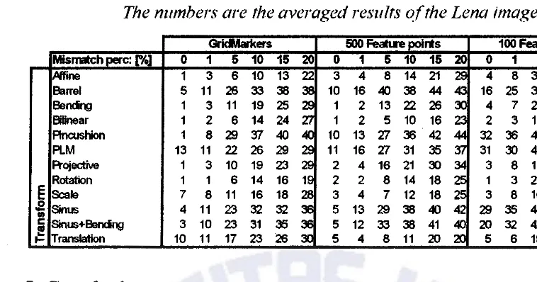
In some cases. the degrees of freedom to introduce mismatches had to be increased. especially in cases when only few feature points were aYailable in the correct match,. in combination with a high percentage of mismatches. In these situations. the feahue points on aYerage are located quite far-off. This is an extra effect. degrading the performance \Yhen fewer correspondence Yectors are used.
Because mismatches were introduced randomly. each realization of mismatches for a giYen percentage is different. Therefore. the experiment was repeated
six
times for each distortion type. For reasons of limited available computational power. this experiment was only performed on the Lena image. using the same correspondence vectors that \Yere used to generate the results listed in Table 2. To assist comparison with the result of the perfect match experiments used in Section 4.3. L these results of this experiment are repeated in Table 2. As in the preyious section. the images are not cropped after the distortions are applied. [image:23.612.53.453.128.599.2]Techne Jurnal Ilmiah Elektroteknika Vol. 8 No. 1 April2009 Hal31- 57
Table 2. Afeasured BERs (in %) HセHエィ・@ e::t.periments with mismatches introduced The numbers are the averaged results of the Lena image.
Gri<Narkers 500 Feabn polrts 100 Feature "rts
c: r'!.] 0 1 5 10 15 20 0 1 5 10 15 0 1 5 10 15
1 3 6 10 13 22 3 4 8 14 21 4 8 30 36 38
Barrel 5 11 26 33 38 10 16 40 38 44 16 25 37 46 46
Bendirg 1 3 11 19 25 1 2 13 22 26 4 7 23 35 42
Ellinear 1 2 6 14 24 1 2 5 10 16 2 3 11 33 33
Anc:ushion 1 8 29 37 40 10 13 Z1 36 42 32 36 45 44 48
PLM 13 11 22 26 29 11 16 Z7 31 35 31 30 41 45 49
A-ojective 1 3 10 19 23 2 4 16 21 30 3 8 19 36 39
Rotation 1 1 6 14 16 2 2 8 14 18 1 3 25 34 40
E
Scare 7 8 11 16 18 3 4 7 12 18 3 8 16 28 41J:!
..,
Sinus 4 11 23 32 32 5 13 29 38 40 29 35 44 tf7 tf7 c Sinus+Bendirg 3 10 23 31 35 5 12 33 38 41 20 32 42 44 46I!
1- Translation 10 11 17 23 26 5 4 8 11 20 5 6 19 25 34
5. Conclusions
In tlris chapter. we have presented two approaches to deal with the watermark
synchronization problem due to the presence of geometric transfonuations. The first
approach deals with tins problem by removing the strict dependence on spatial
synchronization between the watermark and the \Yatermark detector. Thls approach
has the following advantages over classic noise-based schemes:
• Invariant to translations.
• Higher robustness against rotation and scaling.
However. some aspects of the proposed method still have to be improved. In the first
place. the performance of the detector needs further optinrization As shown in our
experiments. thls is critical to the performance of the system. Secondly. the proposed
scheme suffers from security issues. Our experiments suggest that relying solely on
the key used to generate Po and P1 may not be enough to prevent an attacker from
using simple detectors (e.g .. a hlgh-pass filter or randomly generated P1) to get some
indication of the areas where the watermark patch has been embedded.
The second approach discussed in this chapter deals with the synchronization
problem by inverting the geometric distortion and thus recovering the watermark
synchronization. From the experiment results shown in Section 4.3. we can draw the
[image:24.612.88.467.95.294.2]IMPROVING WATERMARK robuNNセGtnessagainst@ GEOMETRIC TRANSFORMATION ATTACK /wan Setyawan
• There is a large improvement of the BER for distortions that actually are
a
polynomial transform. For these transformation classes the achieved BERs
drop below or around 5% for all cases.
• For some extremely non-linear distortions. a large improvement in BER
performance is achievable. Depending on the correspondence vectors used.
large improvements can be made for most highly non-linear distortion types.
Ho,vever. the BERs increase rapidly as the available corresponding points
decrease.
• Uniformly distributed feature points (with pixel accuracy) may gtve less
improvement in BER performance than non-wtifonn distribution. It is most
significant "·hen the image \Vas translated by Y2 pixel.
• The use of orthogonal polynomials makes the proposed approach quite
sensith·e to the presence of mismatches. Even in the case where the applied
geometrical distortion actually is a polynomial. performance goes down
[image:25.612.60.459.189.713.2]rapidly \vith an increasing percentage of mismatches. This can be seen in
Table 4.2. In particular. the presence of mismatches degrades the performance of the scheme when the number of corresponding points are low or when the
geometric distortion is highly non-linear.
6. Acknowledgement
The author is deeply indebted to P.J. 0. Doets who has generously given
permission the work published in [12] and [16]. to be included in Sections 4 and 5 of
this paper.
7. References
1. F.A.P. Petitcolas. R.J. Anderson. M.G. Kuhn. lnfhrmation Hiding- A Survey. in Proceedings of the IEEE. Special Issue: Identification & Protection ofMultimedia Information. pp. 1062-1078. July 1999
2. D. Delannay, J.-F. Delaigle. B. Macq. Compensation ャセHg・ッュ・エイゥ」。ャ@
De.fbrmationsfhr Watermark Extraction in the Digital Cinema Application. in Proceedings of SPIE. Security and Watermarking of Multimedia Contents III. Vol.
Techne Jurnal Ilmiah Elektroteknika Vol. 8 No. 1 April2009 Ha13l- 57
3. G. C. Langelaar. I. Set)·awru1. R.L. Lagendijk. Watermarking Digital image and Video Data: A State-of-the-Art Overview. IEEE Signal Processing Magazine. Vol. 17. No.5. pp. 20-46. September 2000
4. J.J.K.
6
Ruanaidh. T. Pun. Rotation. scale and translation invariant digital image watermarking. in Proceedings ofiEEE. ICIP 1997. Vol. I. pp. 536- 539. Santa Barbara. CA. 19975. P-C Su. C.-C. J. Kuo. Sym.:'111·onized Detection (?fthe Block-based Watermark with Invisible Grid Embedding. in Proceedings of SPIE. Security a11d Watermarking of Multimedia Contents III. Vol. 4314. pp. 406-417. San Jose. CA. 2001
6. M.U. Celik. E.S. Saber. G. Sharma. A.M. Tekalp.Analysis C?fFeature-based G·eometry Invariant Watermarking. in Proceedings of SPIE. Security and Watermarking ofMultimedia Contents Ill Vol. 4314. pp. 261-268. San Jose.
CA. 20<H
7. G.W. Braudaway. F. C. Mintzer. Automatic Recove1y C?flnvisible Image w。エ・イュ。イォセNヲイッュ@ Geometrically Distorted Images. in Proceedings ofSPIE. Security and Watermarking of Multimedia Contents II. Vol. 3971. pp. 74- 81.
San Jose. C A 2000
8. J. Lichtenauer. I. Setyawan. R.L. Lagendijk. T. Kalker. Exhaustive Geometrical Search and the False Positive Watermark Detection Probability, in the
Proceedings of SPIE. Securit)· a11d Watermarking of Multimedia Contents V. Vol.
5020. pp. 203-214. Santa Clara. CA. Januru·y 2003
9. S. VoloshynoYskiy. F. Deguillaume a11d T. Pw1. Multibit digital watermarking robust against local nonlinear geometrical distortions. in the Proceedings of IEEE. ICIP 20tH. Vol.
IlL
pp. 999- 1002.200110. P. Loo. and N. Kingsbury. Motion estimation based registration C?fgeometrically distorted images.fi.Jr watermark recovet)'. Proceedings of SPIE. Security and Watermarking of Multimedia Contents Ill Vol. 4314. pp. 606- 617. San Jose.
CA. 2001
11. A Goshtasby. Image registration by local approximation methods. in Image and Vision Computing. Vol. 6. No.4. pp. 255-261. NoYember 1988
\
1
\
I
IMPROVING WATERMARK ROBUSTNESS AGAINST GEOMETRIC TRANSFORMATION ATTACK /wan Setyawan
13. P. Bas, J.-M. Chassef)· and B. Macq. Geometrically invariant watermarking using feature points, IEEE Trans. on Image Proc .. Vol. 11. No. 9. pp. 1014- 1028.
September 2002.
14. C. Schmid, R. Mohr. and C. Bauckhage. Comparing and evaluating interest points. Proceedings of the 6th Int. Conf. on Computer Vision. pp. 230- 235.
Bombay. 1998.
15. C. Harris and M. Stephens. A combined corner and edge detector. 41h AJyey
Vision ConL pp. 147- 151. 1988.
16. P.J.O. Doets. I. Setya\\·an. R.L. Lagendijk. Complexity-.S'calable Compensation of Geometrical Distortions in Image Watermarking, in the Proceedings of IEEE. ICIP 2003. Vol. I. pp. 513-516. Barcelona. 2003
17. D. Delannay. B. Macq. Methodfi.)r hiding synchronization marks in scale and rotation resilient watermarking schemes. in Proceedings of SPIE. Security and Watermarking of Multimedia Contents IV. Vol. 4675. pp. 520- 529. San Jose.
CA. 2002
18. J. Lichtenauer. I. Setya\Yan. R.L. Lagendijk. Hiding correlation-based watermark templates using secret modulation. to appear in Proceedings of SPIE. Security and Watermarking of Multimedia Contents VI. Vol. 5306. San Jose. CA. 2004
,
.
.. セ@ セᄋZ@ . . . . }''. ,-":··:
lLゥセ^L@
.
セセセセQLZL@
i\;'c;
r-·--··---· ··-·· -.. . ... -- ... ·-"'- -·-··--·-···
I
Tf\': イᄋLセセ@ .-,:.. エMセ@-c.
-2-\) (, 0!
セMGPOヲtセ@
オセ@
57