Abstract. In this paper we are concerned with deterministic wave generation in a hydrodynamic laboratory. A linear wavemaker theory is developed based on the fully dispersive water wave equations. The governing field equation is the Laplace equation for potential flow with several boundary conditions: the dynamic and kinematic boundary condition at the free surface, the lateral boundary condition at the wavemaker and the bottom boundary condition. In this work we consider both single-flap and double-flap wavemakers. The velocity potential and surface wave elevation are derived, and the relation between the propagating wave height and wavemaker stroke is formulated. This formulation is then used to find how to operate the wavemaker in an efficient way to generate the desired propagating waves with minimal disturbances near the wavemaker.
1. INTRODUCTION
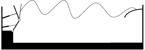
A wave tank in a hydrodynamic laboratory is a facility where maritime struc-tures and ships can be tested by unidirectional waves on a model scale. It usually has a wavemaker at one side and a wave-absorbing beach at the other side. Gen-erally, there are two types of wavemaker which are widely used in hydrodynamic laboratories, namely piston and flap type wavemakers, as shown in Figure 1 and 2. In this paper, we will consider specifically the flap type of wavemaker which is the preferred type for testing ships and structures in deep water. Here deep water means water depth which exceeds approximately a third of the wavelength. As an example, the Indonesian Hydrodynamic Laboratory (IHL) in Surabaya, East Java, Indonesia, uses single and double-flap wavemakers. Flap type wavemakers
Received 15 March 2005, Accepted 27 July 2005.
2000 Mathematics Subject Classification: 76B15.
Key words and Phrases: linear theory, wavemaker, single-flap, double-flap, potential function, surface wave elevation, critical frequency, figure of merit.
are moving partitions which rotate around one or more horizontal axes: single-flap wavemakers rotate about one hinge elevation, and double-flap wavemakers have two degrees of freedom. In order to gain basic insight, first we consider the single flap and then proceed to the double flap.
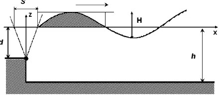
For the single-flap wavemaker, suppose that the wave tank has a still-water depth hand the flap hinge is located at a distance d below the still-water level. Although the hinge can be located above or at the bottom or even below the bottom, we will consider the first case. The bottom of the tank is taken to be flat and horizontal as well as impermeable. It is assumed that the flap moves with a monochromatic frequency and can reach a certain maximum stroke. The generated wave propagates towards the beach, which is considered to be perfectly absorbing, i.e. no wave is reflected. The aim is to find out the relation between the stroke of the wavemaker and the wave height far from the wavemaker. For this purpose we need to know the velocity potential and the surface wave elevation which satisfy the governing equations for the wave tank. Further, the generation of irregular waves is considered.
In the case of a double-flap wavemaker, there are two actuators which move the lower flap (often called the main flap) and the upper flap. Since we use linear theory, the motion of a double-flap wavemaker can be regarded as the superposition of two single flaps. Thus the generated wave is the superposition of the waves pro-duced by each single flap individually. Once the relation between the flap motions and the generated waves is determined, we know how to move the flap in order to generate a certain wave for testing a ship. The prescribed surface waves can also be irregular waves having two or many frequencies. Again, linear superposition can be used to sum solutions with different frequencies. Normally, the upper flap is used for the high frequencies, while the main flap is operated to generate the low frequency waves. Then one needs to determine the critical frequency to decide for which frequency range the waves can be generated more efficiently by either the upper flap or the lower one. A customary way to find this critical frequency is through the use of the Figure of Merit (FoM), often also calledmerit function. As a function of frequencyω, the FoM describes the ratio between the free surface amplitude at the wavemaker, x= 0, and the one at infinity for a monochromatic motion of the wavemaker at frequencyω.
we will give some conclusions and recommendations for possible future research on this topic.
2. SINGLE-FLAP WAVEMAKER THEORY
In this section we will derive the simple shallow-water wavemaker theory of Galvin [3]. After that, the linear theory based on the full equations for water wave motion is discussed in more detail. By finding the ratio between the wave height and the wavemaker stroke, we solve the direct problem and the inverse problem at the same time. With the direct problem we mean that by prescribing the wavemaker stroke, the wave height far from the wavemaker follows as an outcome. The inverse problem is that if we desire to make a certain wave height far away from the wavemaker, we can calculate the stroke needed as an input to the wavemaker.
2.1. Galvin’s Theory for Linear Shallow-Water Waves
Consider a flap type wavemaker as shown at Figure 2. Galvin [3] proposed a simple theory for the generation of waves by this wavemaker, valid in shallow-water. Shallow-water means wave lengthsL much larger than the water depthh, sayL >10h. He reasons that the water displaced by a full stroke of the wavemaker should be equal to the crest volume of the propagating wave. For a flap type of wavemaker with a maximum strokeS at the still-water level and a hinge depthd, the volume of water displaced during a whole stroke is 1
2Sd. The volume of water
in a wave crest for a wave with height H and wave numberk=2π
L, is given by
Z L/2 0
1
2Hsinkx dx= 1 2
H k
µ
1−cos1 2kL
=H
k.
By equating the two volumes, we obtain the ratio of wave heightH and the stroke
S, given by
µ H
S 
Galvin
= 1
2kd. (1)
However, since our main objective is deep-water waves, Galvin’s theory is not of direct use for our applications. But it can be used to check the asymptotic behaviour of our results forkh≪1.
2.2. Linear Theory for Arbitrary Water Depth
Let us start with the mass conservation equation for aninviscid fluid, with mass densityρand velocity vectoru:
∂ρ
∂t +∇(ρu) = 0.
The fluid is assumed to be incompressible and ρ is taken a constant. Then, the mass conservation equation takes the simple form∇ ·u= 0, which is also knows as thecontinuity equation. Furthermore, to good approximation for water waves, the motion may be taken to beirrotational, which physically means that individual fluid particles do not rotate. Mathematically, this implies that the vorticity vanishes,
∇ ×u=0. Then, there exists a single-valued velocity potential Φ such that u=
∇Φ. By combining these two assumptions (incompressibility and irrotationality), we get theLaplace equation ∇2Φ = 0 as a governing equation for the water wave
motion. For our wavemaker problem, it reads
∂2Φ ∂x2 +
∂2Φ
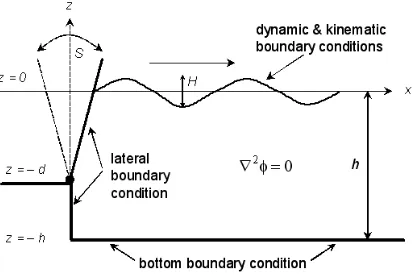
∂z2 = 0, −h≤z≤η(x, t), x≥s(z, t).
The boundary conditions are as follows
• the bottom boundary condition:
∂Φ
Figure 3: The single-flap wavemaker with the governing equation and its boundary conditions.
• the free-surface kinematic boundary condition
∂η ∂t +
∂Φ
∂x ∂η ∂x =
∂Φ
∂z, atz=η(x, t);
• the free-surface dynamic boundary condition
gη+∂Φ
∂t +
1 2
"µ ∂Φ
∂x ¶2
+
µ ∂Φ
∂z ¶2#
= 0, atz=η(x, t);
• the lateral boundary condition at the wavemaker
∂Φ
∂z ∂s ∂z+
∂s ∂t =
∂Φ
∂x, atx=s(z, t).
Therefore we have a boundary value problem. Figure 3 illustrates the gov-erning equation and its boundary conditions for a single-flap wavemaker.
Except for the bottom boundary condition, all boundary conditions are non-linear. Generally, it is hard to find the exact solution for this boundary value problem. The solution will be approximated by linearizing the nonlinear boundary conditions. The linearized equation model for our boundary value problem now reads
∂2Φ ∂x2 +
∂2Φ
∂Φ
∂z = 0, at z = -h;
∂η
∂t =
∂Φ
∂z, at z = 0;
η+1
g ∂Φ
∂t = 0, at z = 0; (2)
∂Φ
∂x =
∂s(z, t)
∂t , at x = 0. (3)
The lateral boundary motions(z, t) for a single-flap wavemaker and sinusoidal flap motion becomes:
s(z, t) =1
2S(z) sin(ωt+ψ) =
1 2S
¡
1 +zd¢
sin(ωt+ψ) ,−d≤z≤0;
0 ,−h≤z≤ −d,
which describes the wavemaker motion with maximum stroke S, wavemaker fre-quencyω and phaseψ.
2.3. Velocity Potential and Wave Height-Stroke Relationship
The general solution for the Laplace equation with the bottom and the free-surface boundary conditions can be determined using the method of separation of variables; and is given by
Φ(x, z, t) = g
ω ·
Acoshk(h+z)
coshkh sin(kx−ωt−ψ) ¸
+ g
ω ·
Ce−κxcosκ(h+z)
cosκh cos(ωt+ψ) ¸
.
The first term is associated with aprogressive wave (also calledpropagating mode), while the second term is associated with a spatially decayingstanding wave and is often called anevanescent mode. The wave numberkof a progressive wave and the wave numberκof an evanescent mode are related to the frequencyω by thelinear dispersion relation
ω2=gktanhkh (4)
and
ω2=−gκtanκh. (5)
By rewriting equation (4) and (5) as
σ2
kh = tanhkh
and
σ2
(a) (b)
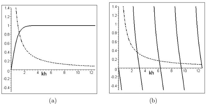
Figure 4: (a) Graphical representation of the linear dispersion relation for the propagating modes, the dash-dot curve represents the plot of σ2
kh while the solid one represents tanhkh.
(b) Graphical representation of the linear dispersion relation for the evanescent modes, showing four of the infinite numbers of roots. The dash-dot curve represents the plot ofσ2
κh, while the solid
ones represent−tanκh.
where σ=qω2h
g is the non-dimensional frequency, it is easy to make plots of the
solutions of these equations. The respective plots forσ= 1 are given in Figure 4. Since there is an infinite number of solutions to equation (5), the solution for the boundary value problem has to be written as
Φ(x, z, t) = g
ω ·
Acoshk(h+z)
coshkh sin(kx−ωt−ψ) ¸
+ g
ω "∞
X
n=1
C[n]e−κ[n]xcosκ
[n](h+z)
cosκ[n]h cos(ωt+ψ) #
,
whereAandC[n] need to be determined. We assume all wave motion to originate
from the wavemaker, so we only consider the positive k >0 and κ[n] >0 to the
dispersion relation (4) and (5). Note that the evanescent modes with amplitudes
C[n], n = 1,2, ... decay to zero far away from the wavemaker. Substitute this
velocity potential into the linearized lateral boundary condition (3) to get
g ω
" Ak
coshkhcoshk(h+z)−
∞
X
n=1
C[n]κ[n]
cosκ[n]hcosκ
[n](h+z) #
=
1 2Sω
¡
1 +zd¢
,−d≤z≤0;
0 ,−h≤z≤ −d,
(6)
It is known from the Sturm-Liouville condition that the set
n
coshk(h+z),cosκ[n](h+z), n= 1,2, . . .o
forms an orthogonal set, namely
Z 0
can be shown to hold because of the linear dispersion relationship (4) and (5). Therefore, to findAboth sides of (6) are multiplied by coshk(h+z) and then integrated over the depth. Due to the orthogonality property, the evanescent terms containingC[n] are eliminated, and thus
A = sinhkh
the depth. It is found that
C[n] = sinκ
Finally, the elevation of the generated surface wave η(x, t) is readily found by applying the linearized dynamic boundary condition at the still-water level, equation (2), namely
so Ais the progressive amplitude andH= 2Ais the wave height.
The wave height of the progressive wave is determined by evaluatingη(x, t) far from wavemaker, where the evanescent modes vanish, namely
η= H
2 cos(kx−ωt−ψ), κ
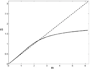
Figure 5: Wave height to stroke ratioH/Sas a function ofkhfor a flap type wavemaker, with
d=h, based on Galvin’s theory, equation (1), (dash-dot curve), and the full linear theory, equation (10), (solid curve).
Since the relation between A and S is known, the ratio of the wave height
H = 2Aand the strokeS is given by
µH
S 
linear
= 4
µsinhkh
kd
¶coshk(h−d) +kdsinhkh−coshkh
2kh+ sinh 2kh . (9)
When the hinge of the flap is located at the bottom of the wave tank we haved=h
and the ratio becomes
µ H S
linear
= 4
µ
sinhkh kh
1 +khsinhkh−coshkh
2kh+ sinh 2kh , (10)
as also found in Dean and Dalrymple [2] and Gilbert et al [4]. Figure 5 shows the plots of wave height to stroke ratio for flap type of wavemaker using the full linear theory, equation (10), compared to Galvin’s theory, equation (1), when d = h. Therefore Galvin’s simple theory gives a good approximation to the wave height to stroke ratio for smallkh.
The wave height to stroke ratio (9) gives the transformation from the stroke of the single-flap wavemaker motion to the progressive wave height generated by that wavemaker motion. For the testing of ships in a hydrodynamic laboratory, normally the wave heightH of a monochromatic signal is specified. Using (9), we now can determine the required stroke of the wavemaker.
Often, the desired waves are not regular but irregular. These waves can be represented as a summation of several monochromatic waves, namely
η(x, t) =
N
X
i=1
1
2Hicos(kix−ωit−ψi), (11)
where each wave number - frequency pair (ki, ωi) satisfies the linear dispersion
Figure 6: Schematic figure of a double-flap wavemaker structure.
moved with the flap motion
s(z, t) =
1 2
³
1 +z
d ´XN
i=1
Sisin(ωit+ψi) ,−d≤z≤0;
0 ,−h≤z≤ −d,
where every Si satisfies the wave height to stroke ratio (9) associated with the
corresponding wave heightHi.
3. DOUBLE-FLAP WAVEMAKER THEORY
This section is started by the formulation of the double-flap wavemaker mo-tion and the surface waves generated by the flap movement. This formulamo-tion is referred to as the direct problem. Once the relation between the flap strokes and the height of the generated progressive wave is found we proceed with the inverse problem. There, the desired surface wave at a position far from the wavemaker is given, generally in the form of an irregular wave. Hence it can be represented as a summation of a finite number of regular waves with different frequencies and am-plitudes. Regular waves with high frequencies are generated by moving the upper flap, while the low-frequency waves are generated by the main flap. Thus we need to find the critical frequency that separates the frequency range for which one shall operate either the upper flap or the main flap.
3.1. The Generated Surface Waves
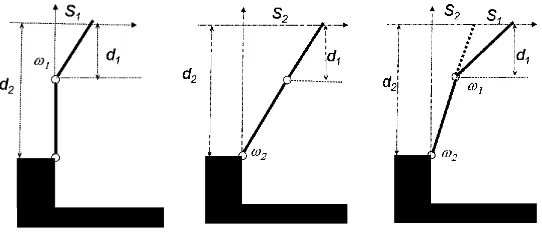
(left), main flap motion (middle), combination of upper and main flap (right).
linear theory of wavemakers, then the last case is just the superposition of the two preceding cases.
The cases when only the upper flap moves with stroke S1 or the main flap with strokeS2has been treated in the previous section on single-flap motion. Here, we will discuss the case of both flaps moving simultaneusly, the upper flap with frequencyω1 and the main flap with frequencyω2.
The horizontal displacement s(z, t) when both the upper flap and the main flap move together is given by
s(z, t) =
By linear superposition, the corresponding velocity potential Φ for this con-dition is the sum of the velocity potentials Φ1 and Φ2, namely
Φ(x, z, t) = g
2 are as given for the single-flap case. The
to the linearized dynamic boundary condition (2):
η(x, t) = −1
g ∂Φ
∂t ¯ ¯ ¯ ¯
z=0
= A1cos(k1x−ω1t−ψ1) +
∞
X
n=1
C1[n]e−κ
[n]
1 xsin(ω1t+ψ1)
+ A2cos(k2x−ω2t−ψ2) +
∞
X
n=1
C2[n]e−κ
[n]
2 xsin(ω2t+ψ2).
The generated progressive wave is determined by evaluatingη(x, t) far from wavemaker, where the evanescent modes vanish:
η(x, t) = A1cos(k1x−ω1t−ψ1) +A2cos(k2x−ω2t−ψ2)
= H1
2 cos(k1x−ω1t−ψ1) +
H2
2 cos(k2x−ω2t−ψ2),
where
H1= 4
µsinhk1h
k1d1
¶coshk1(h−d1) +k1d1sinhk1h−coshk1h
2k1h+ sinh 2k1h S1,
and
H2= 4
µsinhk2h
k2d2
¶coshk2(h−d2) +k2d2sinhk2h−coshk2h
2k2h+ sinh 2k2h S2,
relate the wave heights H1 and H2 to the strokes S1 and S2, respectively. Note, that for the caseω16=ω2, the maximum wave height isH1+H2 and the minimum wave height is|H1−H2|in the generated bi-chromatic wave pattern.
3.2. Inverse Problem
ratio of the surface wave amplitude at the wavemaker and the one far from the wavemaker. It reads (Dalzell [1]):
FoM(ω) =
where A is the propagating mode amplitude and C[n] are the evanescent mode
amplitudes. Note that the FoM is always larger or equal to one. The ideal case is if the FoM equals one. Then there are no evanescent modes, which is desirable since the increased wave height near the wavemaker, due to the presence of the evanescent modes, may for instance trigger undesirable wave breaking near the wavemaker. Let the FoM of the upper flap be denoted by FoM1and the one of the
main flap be denoted by FoM2, then there exists a critical frequencyω∗ such that
FoM1(ω∗) = FoM2(ω∗). The plots of FoM1(ω∗) and FoM2(ω∗) can easily be drawn
when we have found the progressive wave numberkand evanescent wave numbers
κ[n] corresponding to a certain range ofω by solving thelinear dispersion relation
(4) and (5).
For low frequencies the upper-flap FoM1(ω) will be higher than the
main-flap FoM2(ω), and above a critical frequency ω∗, it will be just opposite. The
critical frequency is obtained where the plotted lines of the FoM cross each other. Accordingly, for 0< ω≤ω∗, the main flap is used, and forω > ω∗, the upper flap
is used.
By re-arranging the terms and taking the square root of both sides, we get
By substituting these quantities into (12), we have the following relation atω=ω∗:
coshk∗(h−d1) +k∗d1sinh(k∗h)−cosh(k∗h)
∗ , andω∗ satisfy the linear dispersion relation
(ω∗)2=gk∗tanh(k∗h) =−gκ[n]
∗ tan(κ[∗n]h).
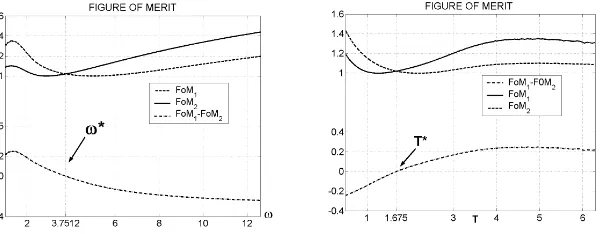
The configuration of the double-flap wavemaker in the towing tank of the IHL is: h= 5.5 m depth and the position of hinges is atd1= 0.83 m andd2= 2.55 m below the still-water level. For this configuration, we have drawn the plots of FoM1
and FoM2 in the frequency domain as well as in the wave period domain, as shown
in Figure 8. It can be noticed that for the IHL towing tank configuration the critical frequency isω∗= 3.7512 rad/s, and the critical period is T∗ = 2π/ω∗= 1.675 sec.
It can also be observed that at the critical point, the value of FoM1as well as FoM2
of wave period (right), forh= 5.5 m,d1= 0.83 m, andd2= 2.55 m.
3.2.2. Irregular wave motion for the double-flap wavemaker
Let the desired irregular waves, to be generated by the double-flap wavemaker, be expressed by (11). In order to distinguish the wave components that have to be generated by the upper flap from the ones that will be generated by the main flap, the desired wave field needs to be separated into two parts:
η(x, t) =
where ω1i > ω∗ denote the frequencies of the wave components that need to be
generated by the upper flap, while 0< ω2i ≤ω∗ are the frequencies of the wave
components which will be sent to the main flap. SubscriptsH andLindicate high and low frequency, respectively.
Since we are concerned with linear theory, the flap motion is the superposition of the flap motion by the individual wave components. The motion of the double-flap wavemaker to generate the irregular wave field (14) becomes
S2i =
µ k2
id2
4 sinhk2ih
¶ 2k2
ih+ sinh 2k2ih
coshk2i(h−d2) +k2id2sinhk2ih−coshk2ihH2i,
andkjisatisfy the linear dispersion relation (4) with respect toωji.
4. CONCLUDING REMARKS
In this paper we consider a wave tank that has a wavemaker on one side and an absorbing beach on the other side. A linear theory for the flap type of wavemaker based on the full equation for linear water waves is presented. It has been discussed for both the single-flap and the double-flap wavemaker motion. By solving the governing equation with its corresponding boundary conditions, it turns out that the surface wave elevation contains a progressive wave part and an evanescent modes part, where the latter part vanishes far from the wavemaker. Furthermore, there is an explicit relation between the wave height of the generated surface wave elevation in the far field and the stroke of the wavemaker. This relation depends explicitly on the water depth, the hinge position, and the wave frequency. Therefore, we are able to solve both the direct problem, where the wavemaker stroke is prescribed and the wave height is the outcome, as well as the inverse problem, where the wave height is given and the wavemaker stroke follows as a result. The latter case is more likely to be the desired situation for performing experiments in the laboratory, allowing one to control the wavemaker motion in such away that a desired wave field is realized.
We also apply linear theory to the case when the wavemaker has double flaps. This type of the wavemaker is useful in generating waves in a wider range of frequencies. The double-flap wavemaker has two actuators that move the upper flap and the main flap. Normally, the upper flap is used to generate the wave components with a frequency higher than a certain critical frequencyω∗, while the
main flap is used to generate the wave components with frequencies belowω∗. By
applying the Figure of Merit (FoM) on the wavemaker flaps, one can determine the critical frequencyω∗, see equation (13). The FoM depends only on the wave tank
depth and the position of the hinges. For a certain wave tank configuration, the critical frequency has to be determined. Hence, one can decide when to use either the upper flap or the main flap. Since the calculation is based on linear theory, linear superposition can be used to construct an irregular wave field.
This wavemaker theory can be extended using nonlinear theory. This will involve mode generation, as a consequence of nonlinear interaction among mono-chromatic wave components at higher order. This nonlinear extension is expected to be executed in similar research in the future.
REFERENCES
1. J.F. Dalzell, “Analysis of Articulated Flap Wavemakers”, Technical Report TR75 -1, ABA Electromechanical Systems, Pinellas Park, Florida, USA, March 1975. 2. R.G. Dean and R.A. Dalrymple,Water Wave Mechanics for Engineers and
Scien-tists, Volume2of Advanced Series on Ocean Engineering, World Scientific, Singapore, 1991.
3. C.J. Galvin, Jr, “Wave Height Prediction for Wave Generators in Shallow-Water”, Tech Memo4, U.S. Army, Coastal Engineering Research center, March 1964.
4. G. Gilbert, D.M. Thompson and A.J. Brewer, “Design Curves for Regular and Random Wave Generators”,J. Hydraulic Res.2, no. 2, 1971, 163 – 196.
5. W.H. Press, B.P. Flannery and S.A. Teukolsky, Numerical Recipes in FOR-TRAN: The Art of Scientific Computing, Cambridge University Press, Cambridge, 1992.
W.M. Kusumawinahyu: Department of Mathematics, Institut Teknologi Bandung, Jl. Ganesha 10 Bandung 40132, Indonesia.
Department of Mathematics, Universitas Brawijaya, Jl. May. Jend. Haryono 169 Malang 65145, Indonesia.
E-mail: [email protected]
N. Karjanto: Applied Analysis and Mathematical Physics Group, Department of Ap-plied Mathematics, University of Twente, P.O. Box 217, 7500 AE, Enschede, The Nether-lands.
E-mail: [email protected]