M O T O R I Z E D PA NO R A M I C C A M E R A
M O UNT – C A L I B R A T I O N A ND I M A G E C A PT UR E
H. K auhanen
a, *
, P. R önnholm
a
, V .V . L ehtola
a
a
A alto University, D epartment of B uilt E nvironment, Po. B ox 15800, 00076 A A L T O, F inland, ( heikki.kauhanen, petri.ronnholm, ville.lehtola)@ aalto.fi
C ommission V , W G V /3
K E Y W OR D S : C amera mount, panoramic imaging, calibration, automation
A B S T R A C T :
Panoramic cameras have become popular because they provide impressive and immerse experience of the scene and allow several
interesting applications. A mong the large variation of panoramic camera systems, we have focused on concentric panoramic imaging
with a frame camera. In order to establish the concentric image acquisition, the camera mount must be calibrated so that the projection centre of the camera is located at the rotation centre of the mount. F or this purpose, we developed a novel mount calibration method, which allows an accurate recovery of the rotation centre in two image acquisition steps. In addition, we have built a motorized camera
mount that can self-calibrate the camera position within the mount, given the previously solved rotation centre, and then be used to
automaticall y capture panoramic images. Hence, we have streamlined the previously laborious manual phase of iterative position calibration, but also automated the capturing of panoramic images. F or validation purposes, reference results from a conventional
manual mount are provided. In the case of non-motorized mount, the average distance between the projection centre of the camera and the rotation centre of the mount was 0.253 mm and the standard deviation was 0.161 mm. F or the motorized mount, the corresponding
average distance and standard deviation were 0.549 mm and 0.404 mm, respecti vely.
1. I NT R OD UC T I O N
Panoramic photographs have been created almost as early as
there have been cameras. Panoramic images can provide impressive and immerse experience of the scene. R ecently
panoramic images have attracted significant amount of attention. C onsumer-grade cameras nowadays have easy interfaces for
taking and creating panoramic images. Google S treet V iew has proven how effective panoramic images can be for virtual
navigation. In addition, the development of virtual glasses has
created a need and interest to collect panoramic i mages.
T here are various methods how to create panoramic images. It is
even possible to acquire stereo-panoramic images ( e.g., Huang
and Hung, 1997). In fixed panoramic systems no moving parts are needed. S uch systems typically include several cameras or
images are taken through mirrors with a single sensor. Multi-camera systems are typicall y designed to have a diverging
camera arrangement which does not provide the common projection centre to sub-images. A n alternative is to arrange
cameras in such a way that they share the common perspective centre. T his can be done by using mirror pyramids. C ameras can
be placed in such a way that their virtual projection centres behind the mirrors coincide ( Nalwa, 1996; T an et al., 2004) . In
this case, sub-images can safely be merged into a single panoramic image mosaic, also for measuring purposes. F ixed
systems can alternatively rely on a single camera sensor, if a curved mirror is placed in the front of the camera. T ypical
implementations utilize convex mirrors that provide 360° horizontal viewing angle ( e.g., Gluckman et al. 1998; C hen et al.,
2009) .
*
C orresponding author
Panoramic images can be captured also with a rotating frame or
a linear array camera. T ypically, these systems have only one camera sensor. F or visualization purposes, any camera mount or
even a free-hand rotation is sufficient, however, resulting in separate projection centres of all sub-images. If final panoramic
images are applied for measurements ( F angi and Nardinocchi, 2013) , the concentric image acquisition is desired ( Haggrén et al.,
1998) . If every sub-image has the same projection centre, there are no perspective differences between sub-images. T he presence
of perspective differences can make seamless image stitching more difficult or impossible. However, if objects are far away
from the camera, small deviations from the ideal concentric case cause very small errors at the image plane (K auhanen and
R önnholm, 2012). On the other hand, by ensuring the concentric
data acquisition the best accuracy for image measurements can be achieved.
B oth fixed and rotating panorami c cameras need to be calibrated.
In the case of non-concentric systems, measurements should be done only using original sub-images which means their interior
and exterior orientations need to be solved. Pre-knowledge of allowed camera trajectories because of the mount can be added
as constraints in bundle adjustment ( Heikkilä, 2005). T he concentric multi-camera systems can be calibrated, in which case
all relative orientations of sub-images are directl y known if the directions of optical axes of sub-images can be detected. In the
case of mirror-based systems, the effect of the mirror should be included in the camera calibration. R otating concentric systems
require both the known interior and relative orientations of the camera and, additionally, the accurate placing of camera in the
mount in order to ensure the rotation centre and the projection centre to coincide. T herefore, also the camera mount should be
calibrated.
S chneider and Maas (2003) solved the calibration of a linear array panoramic camera with a point-based calibration frame
whereas Parian and Gruen ( 2005) solved the corresponding
calibration with 3D straight lines. K ukko ( 2004) presented an interactive method how to find the correct camera placement of
the rotating panoramic camera mount in order to achieve the concentric image acquisition. T he mount had the possibility to
adjust the camera location within the system ( Haggren et al., 2004) . T he calibration method utilized multi-distance calibration
targets. T he general idea was to place small targets to at least two different distances from the camera so that the nearest target
occluded the more distant target. T he camera was then manually rotated around all axes separately and if the targets did not move
in relation to each other on the image plane, the camera projection centre was properly placed to the rotation axes crossing of the
panoramic mount. T his was an iterative process which made the process very ti me consuming. T he accuracy of the camera
placement was reported to be 1 mm.
T he aim of our research is to develop a method for solving the
amounts and directions of necessary camera shifts to calibrate a panoramic frame camera mount and therefore ensure the concentric image capturing. In contrast to the laborious iterative
camera adjustment process of the method, such as in K ukko
(2004) and in B arazzetti et al. (2013) , we want to find the correct shifts of the camera directl y. In addition, we design and build a
motorized panoramic frame camera system, which allows automatized panoramic image acquisition. Our system can also
change the camera location wi thin the mount allowing the computer-aided calibration. F or validation purposes, we test our
calibration method also with an older non-motorized panoramic mount.
T he paper is organized as follows. T he materials and methods are
described in S ection 2 including the description of the old non-motorized panoramic camera mount and the novel non-motorized
panoramic camera mount, as well as the proposed calibration process. T he results have been collected in S ection 3. A fter the
discussion in S ection 4 we summarize the conclusions in S ection 5.
2. M A T E R I A L S A ND M E T H OD S
2.1 T he r eference mount and the calibr ati on tar get
In order to compare the accuracy of our motorized platform, we
gathered reference data from a non-motorized, manuall y operable
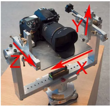
panoramic mount (F igure 1) developed by Pöntinen (2004). T he reference mount allows similar spherical image acquisition
through adjustments for the camera pose, as our motorized version. F or operational convenience, the reference mount is
made from aluminium and has a very robust structure.
F igure 1. T he non-motorized reference platform and the
calibration rig.
F igure 2 illustrates available directions for moving the camera within the mount. Moving the camera in the X and Z directions
change the location of the camera in the horizontal plane that is
needed for adjusting the projection centre at the vertical rotation axis of the mount. T he Y direction allows moving of the camera
upwards and downwards, which is needed to place the projection centre at the horizontal rotation axis. A ll the shifts of the camera
are done manuall y using a screwdriver. If it is known how much the camera needs to be moved, the amount of shifts can be
measured with a caliper. In the background of F igure 1, there is the calibration rig that was compatible with A ustralis software
and was utilized for the calibration.
F igure 2. T he correction directions of the mount calibration.
2.2 T he novel motor ized camer a mount
T he motorized panoramic mount built in this project aimed to automate metric image capture and calibration tasks involved in
photogrammetric use of panoramic imaging. C ommercially available panoramic mounts already offer highly automated
image capture but usually lack the accurate calibration capabilities that are required in photogrammetric applications.
C oncentricity calibration requires the platform to have means to translate the camera in three directions perpendicular to each
other. T he correctable axes of the motorized mount were selected similarly than with the non-motorized system ( F igure 2). T he Z
axis is pointing to the same direction than the optical axis of the camera, the X axis is pointing to the right as seen from inside of
the camera and the Y axis is pointing up. In practice, the axes may not be exactl y perpendicular to each other because of the
mount structure, which potentially can cause some errors in the concentricity calibration. T he hardware consists of six motors out
of which three are responsible for X , Y and Z translational movements required for the concentric calibration of the optical
system and other three are needed to rotate the platform over yaw, pitch and roll axes (F igure 3). T he actual implementation can be
seen in F igure 4.
F igure 3. T he structural image of the motorized panoramic
mount.
F igure 4. T he motorized camera mount.
T he hardware is based on modified D Y S E agle E ye brushless
gi mbal. B rushless gimbals are typicall y used in Unmanned A erial V ehicle (UA V ) industry to stabilize the image capture. E agle E ye
gi mbal features three brushless motors to stabilize all three rotation axes (yaw, pitch, roll) and an MPU6050 Inertial
Measurement Unit ( IMU). T he IMU can be used to find out the orientation and movement of the mount. Originally, that
information is an input to the A rduino-based control circuit that can calculate in which directions the brushless motors need to be
driven in order to keep the platform level and pointing the right direction. B rushless motors are preferred instead of servomotors
because for the stabilization of the mount, a very fast operation is needed and brushless motors are able to provide that while also
being mechanicall y less complex than servomotors. It should be noted, however, that brushless motors allow no positional
feedback and thus the orientation of the platform relies solely on
the IMU data.
F or terrestrial applications the stabilization is not critical because the platform will be mounted on a stable tripod or clamped to
some solid surface. T he brushless gimbal system was chosen to make the mount to be able to also perform mobile tasks such as
mounting on a rover or UA V in the future. However, the A rduino control circuit also accepts servo signal inputs to control the
rotational motors. T his is intended to provide means to aim the camera in UA V applications from the ground control station. In
this application, we use the controls to turn the camera around yaw and pitch axes to produce panoramic images. T he roll
rotation is allowed to change to keep the camera level according to the IMU sensor readings. In practice, because the mount is
used on a relatively level surface, the variation of the mount roll
angle is small.
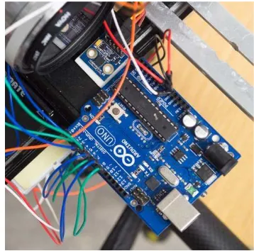
F or the automatic controlling of the mount, we have attached an A rduino Uno control circuit (F igure 5) which we use to generate
three separate signals to the motors and one signal to trigger the
camera. One servo signal is fed into the brushless gimbal control circuit to control the yaw axis rotation and the other servo signal
controls the pitch axis. In addition we also use a third servo signal to set the roll angle but it is kept fixed resulting in self levelling
mount. T he camera trigger si gnal is fed directly into the trigger port of the camera if the camera is compatible with the 5V trigger
signal. Normall y commercial digital cameras offer triggering by shorting the trigger signal pin to ground and thus we had to put a
transistor into the 5V A rduino signal path and use the transistor as a switch to trigger the camera.
F igure 5. T he A rduino control circuit is operating the mount
automaticall y. S maller blue circuit board is the MPU6050 IMU.
T he A rduino Uno control circuit is programmed to provide a
suitable horizontal and vertical overlap between images depending on the image capture requirements. Generall y
locations where there are high amount of details to aid the image
stitching, less overlap is required. T he platform rotation is stopped for each image capture to provide the highest possible image quality. C urrently we have programmed the platform to
take an image every six seconds, but it would also be possible to
improve the system by reading accelerometer data from the IMU and take sub-images as soon as the mount has stabilized from the
rotational movement. T his would accelerate the image capture without reducing the image quality.
F or the concentricity calibration, we need three motorized
translational axes. F or the X and Z directions this is done by modifying a camera equipment macro slide by attaching a S T
-PM35-15-11C stepper motor to a M4-0.7 thread rod which connects to a nut attached to the moving sled part of the macro
slide. E ach stepper motor is controlled by the S parkfun E asy S tepper control board which is controlled by the A rduino Uno
control board. T hat way we can control the movement of the sled by spinning the stepper motor by a certain amount of steps. E ach
step of the motor corresponds to approximately 1.8 µ m movement of the sled. F or the Y direction translation, two slides
are required making synchronized operation essential. T he hardware for this is the same as with X and Z axes but two motors
need to be spun at the same ti me by the same amount of steps to ensure the Y translation stays level and does not jerk.
2.3 S ystem calibr ation algor ithm
T he concentricity calibration is based on observations how the projection centres of sub-images move when the mount is rotated.
In the case of the ideal concentric data acquisition, the projection
centres of sub-images do not move. Our method solves the concentricity calibration using a numerical method where the
eccentricity of the camera rotation is calculated and as a result we get X , Y and Z shifts for the correction of the camera location
within the mount. A pplying corrections to the non-motorized mount requires manual shifts of the camera. T he motorized
mount can automaticall y drive the camera to the crossing of the rotational axes as shown in F igure 3.
A s for preliminary measures, the ( physical) camera is calibrated
for interior orientation including lens distortions. T his is done using A ustralis and calibration target (F igure 1) , which also
yields the 3D (homogenous) point coordinates of the calibration rig { xi} . F or convenience, we choose the global coordinates so
that the camera Ci is pointing towards x-axis. T he problem itself is two-fold. F irst, we want to bring the centre of rotation of the
platform Crot into the same coordinate system with the cameras, and second, we want to minimize the distance between these. In
order to determine Crot, we need to rotate the camera while it is mount is kept fixed, at first. A t least three photos of the test field
are taken while rotating the camera, a constraint explained later, resulting into camera positions that we index with i. T hen for
for ideal points and an optical axis oi for each (virtual) camera. In the global coordinates, the camera locations are written as
C =− 4 , (3)
where R-1=RT by orthogonality. T he practical operation is
mainly li mited due to the field of view (F oV ) of the camera,
because the test field must be visible in each of these photos for resectioning purposes. T his culminates into that the baseline
between camera positions in our setup is 4 cm at maximum, with concurrent positions being about 0.5 cm apart.
Using the camera locations Ci on the X Z -plane and the a-priori
knowledge that they lie on the perimeter of a circle, we perform a least-squares circular fit to find the centre of the circle, which
is the centre of rotation of the platform Crot. F ormally, we
quantities obtained through iteration. T he previously stated requirement of at least three photos, N=3, is a practical minimum
to obtain a solution for the circular fit. R edundancy in form of more images is used to avoid mul tiple minima ( see C hernov and
L esort, 2005) , but also for error determination.
T he distance between the projection centre of the cameras Ciand
the centre of rotation Crot now has to be separated into orthogonal components in order to recover the underlying X and Z -directional displacements. T his is conveniently done in two steps.
F irst, by computing the distance of the point Crot on the X -Z plane
to the line, aiX + biZ + ci = 0, drawn by the optical axis of each of
the camera positions i, which is the X -directional displacement.
S econd, by minimizing the distance of the point Crot on the same plane to the line drawn perpendicularly to the optical axis of each
of the camera positions i, which is the Z -directional how the camera must be translated in order to have its centre of
projection on the top of the rotation centre of the mount. Now only Y displacement remains, which is recovered in a similar
manner by using the rotation over the pitch axis. Note that while
doing this, we obtain the Z shift again, but this time it ought to be close to zero.
T he process can be streamlined into one step by rotating multiple
angles during the image capture phase. T hen the recovery of the displacements in full 3D can be done from a single set of i mages.
However, we experienced that in this case, mechanical reasons
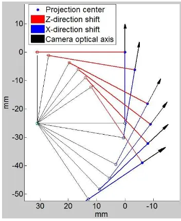
sub-images were solved using the calibration rig. T he result can be seen in F igures 6 and 7, in which blue filled circles present the
locations of the projection centres of images. A s can be seen,
projection centres form a circular path. T he second step is illustrated in F igures 6 and 7, in which we draw a line from each
projection centre facing the direction of the optical axis (blue arrows) and other line perpendicular to that and facing the direction obtained from camera orientation roll parameter ( red
lines) . T hen for each of those lines, a line is drawn from the yaw
axis, which was obtained as the centre point of the circle drawn through projection centre coordinates, perpendicularly to each
line drawn in the previous step. T hese are illustrated by thin black lines. T his gives us two sets of resections. T hese resections are
marked in F igures 6 and 7 as blue and red circles. T he translation needed to drive the camera into the yaw axis in the X direction
(ΔX in F igure 3) is the length of the blue arrows. In practice they are not all the same length and thus an average length is used.
S imilarly the Z direction translation ( ΔZ in F igure 3) can be ISPRS Annals of the Photogrammetry, Remote Sensing and Spatial Information Sciences, Volume III-5, 2016
obtained as the average length of the red lines. T his process was repeated for both the non-motorized and motorized mounts.
F igure 6. Geometry to determine the X and Z translations for
the concentric imaging in the case of the non-motorized mount.
F igure 7. Geometry to determine the X and Z translations for
the concentric imaging in the case of the motorized platform.
F igures 8 and 9 show geometry to determine the Y direction
translation needed to move the camera projection centre into pitch axis. F or the Y direction shift, only the radius of the circle
fitted to the projection centre coordinates needs to be considered because the first step of the calibration has already solved the Z
direction movement. T hus lines drawn from each projection
centre facing down should all resect at one point which is also the centre of the circle fitted to projection centres of the cameras and each line should have the same length than the radius of the fitted
circle.
A fter this step the concentricity calibration is complete. F igure 8 shows that the lines drawn from each camera do not intersect
precisely at one point which results in error in the calibration
while the motorized mount (F igure 9) results in more precise Y direction translational movements leading to a more precise
intersection.
F igure 8. Geometry to determine the Y translation for the concentric imaging in the case of the non-motorized mount.
F igure 9. Geometry to determine the Y translation for the concentric imaging in the case of the motorized mount.
Once we had properly placed the camera in the panoramic mount, we could test for the accuracy of the calibration by photographing
the calibration rig again while rotating the camera in the yaw and pitch directions. A ll the projection centres should locate at the
same place if the ideal calibration is achieved. In practice there is always some residual error. T he change of the projection centre
movements during the rotations are illustrated in F igures 10 and
11 (right images), in which red points are the projection centres due to pitch rotations and white points presents the projection
centres due to yaw rotations before the calibration. T he left images in F igures 10 and F igure 11 highlight how the projection
centres move along the arc of circles. A fter the calibration the projection centres of rotated sub-images ( yellow points) are close
to each other’s without any regular pattern, as expected. ISPRS Annals of the Photogrammetry, Remote Sensing and Spatial Information Sciences, Volume III-5, 2016
F igure 10. T he calibration of the non-motorized camera mount. T he sub-image locations before the mount calibration are
presented in the left image. In the right the image, yellow dots represent the sub-image locations after the mount calibration.
F igure 11. T he calibration of the motorized camera mount. T he sub-image locations before the mount calibration are presented
in the left image. In the right image, the yellow dots represent the sub-image locations after the mount calibration.
T he size of circles in F igures 10 and 11 depend on the initial
position of the camera with respect to the rotation centre of the mount. In T able 1, the shift values for each three correction
directions are presented. T he non-motorized and motorized mounts were corrected according to these values. T he
non-motorized mount required manual moving of the camera, but the motorized mount used motors to apply shifts.
non-motorized
mount
motorized mount
X (mm) 9.9440 23.9523
Z (mm) 29.3630 31.5232
Y (mm) 8.8553 32.6385
T able 1. T he correction shifts of the camera found by the calibration algorithm. T he X and Z shifts move the projection
centre of the camera at the top of the vertical rotation axis and the Y shift aligns it with the horizontal rotation axis.
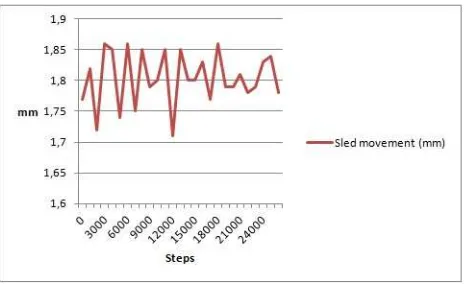
T o ensure that the motorized mount can reliably and consistently
perform given shifts, a test was conducted where the calibration sled was moved in 1000 step increments for a total of 27 times. T he total displacement resulted into a 48.6899 mm movement of
the sled. T he displacement of the sled was measured with a digital
caliper after each 1000 steps. D ata is represented in F igure 12. T he average movement of the sled was 1.8033 mm for every
1000 steps. S tandard deviation of movements was 0.0430 mm. T he average movement of 1.8 µ m per step was used when
translating the camera into correct position acquired from the
calibration algorithm.
F igure 12. T he repeatability test of the camera sled. T he camera
was moved 27 times for 1000 motor steps each resulting in an average movement of 1.8033 mm.
In our calibration method, we performed the shifts of the camera only once according to computed optimal shifting values. A fter
the correction we repeated the calibration measurements in order to verify if our correction had succeeded. T he yellow dots in
F igures 10 and 11 are the projection centres of sub-images after the calibration. E xpectedly, they are now very close to each other.
W e computed the mass centre from all sub-image locations. In
table 2, we present the average distances between the mass centre and all sub-images for both mounts and corresponding standard
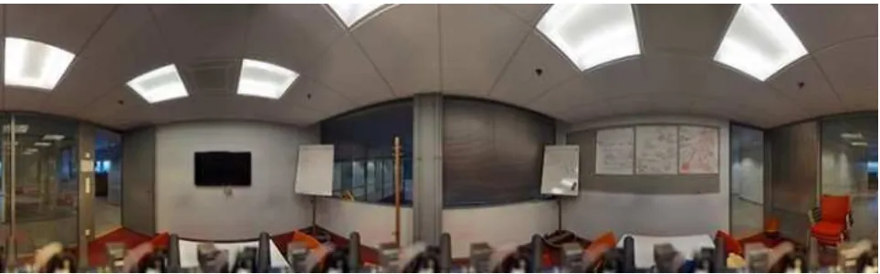
deviations. In addition, after the system calibration we captured an example of a panoramic i mage which is shown in F igure 13.
non-motorized
mount
motorized mount
average distance (mm)
0.253 0.549
standard deviation ( mm)
0.161 0.404
T able 2. A verage distances and standard deviations of the projection centres from the mass centre that was calculated from
all available camera centres after the mounts were calibrated. ISPRS Annals of the Photogrammetry, Remote Sensing and Spatial Information Sciences, Volume III-5, 2016
4. D I S C US S I ON
C alibrating the camera and the non-motorized mount is quite
time-consuming process leading to the reduced flexibility of the system. T he new calibrations are needed if aperture, zoom or
focus of the camera is changed. W ith the motorized mount it is possible to quickly calibrate the concentricity of the system, so
changing camera settings or even changing the camera becomes feasible. F or this we need to be able to find out the interior
orientation of the camera on site and then run our concentricity
calibration algorithm for driving the camera into the correct position in the panoramic mount. It is possible to use a similar
calibration rig than we used for the laboratory calibration of our system but also natural targets such as furniture, walls, ceiling,
floor, and doors could be used for the in-situ calibration. T here are also many commercial panoramic mounts ( for example
Gigapan E pic series, www.gigapan.com) that can achieve the same level of automatization in image capture than our prototype
but they lack the precise automated concentricity calibration possibilities.
T he results in T able 2 indicate that the final calibration accuracy
of the motorized mount was slightly worse than of the non-motorized mount even if F igure 8 reveals that the non-non-motorized
mount has more misalignment between rotation axes. T he reason for this is most likely dependent on two issues. F irstly, the
physical structure of the motorized mount is not as rigid as of the non-motorized mount. S econdly, the time interval of image
capture was set to a constant. T herefore, the system did not check if the movement of the mount was stabilized for sure. In the
future, we will examine how to strengthen the mount structure
and optimize the image acquisition algorithm more intelligent.
T he time it takes to capture a full spherical panorama with the
non-motorized mount using normal 45° lens with 50% overlap,
for example, can take up to an hour if lighting conditions require the use of long exposure time in the order of seconds. In that kind
of situations the platform needs to be stable and free of vibrations. T hus in manual operation, a remote trigger needs to be used
because the operator is not allowed to touch the mount when the exposure is about to start. T his increases significantly the ti me
required to take the photographs. In the motorized version, the image acquisition is automated making it fast. In addition, we
could read the accelerations of the platform from IMU and start the exposure as soon as the platform is deemed stable. W e could
also start to rotate to the next orientation as soon as the image has been captured.
W hen taking hundreds of images per panoramic station this saves
a large amount of time. T hese extensions, however, have not yet been implemented in our system.
In addition to improved speed of operation and versatility, our motorized mount also offers greatl y i mproved accuracy of translational calibration movements. A s can be seen from F igures
8 and 9, there is a clear improvement in the intersection accuracy of the Y direction calibration. T his is caused by much better
repeatability of the calibration movements offered by the stepper
motor drive approach. In practice this means that once the mechanical robustness of the motorized mount has been
improved, the system offers not only better speed of operation and versatility of quickly changi ng the camera system, but also
better geometrical accuracy than conventional manually calibrated panoramic mounts. W e discuss the eccentricity error
more elaborately in our previous publication (K auhanen and R önnholm, 2012) . In the example case of this paper, stitching of
images succeeded without visible discontinuities ( F igure 13).
In many photogrammetric applications there is a need to cover the area being measured from many different viewpoints. Using
the non-motorized panoramic camera this requires careful planning because the amount of panoramic stations one can
produce in a given time is limited. Our prototype offers stabilized
image capture while moving so if the platform was mounted on a rover for example, the camera could be used to aid the system to navigate to a proper place to take the panoramic i mage while
recording a video footage which could be used for S F M
reconstruction, for example. T hat way the same system would produce mobile mapping data as well as high resolution
panoramic images coupled with the versatility to change the optical configuration of the system thanks to field calibration
possibilities offered by the motorized concentricity calibration.
5. C ONC L US I O NS
W e introduced a novel calibration method to position the centre
of projection of the camera at the rotation centre of a panoramic camera mount. In addition, we designed and built a motorized
camera mount that allows both the use of the previous position calibration method, and an automatic image acquisition. Our
method can be applied to calibrate any panoramic mount having motorized or manual adjustment for camera placement provided
the mount has enough space to move the camera in all X Y Z directions in order of couple of centimetres from the correct
projection centre placement.
F igure 13. Panoramic i mage acquired with the motorized mount after the mount calibration. ISPRS Annals of the Photogrammetry, Remote Sensing and Spatial Information Sciences, Volume III-5, 2016
T he mount calibration process included the interior orientation of the camera, solving locations of projection centres of sub-images
after rotating camera, computing of necessary shifts of the
camera within the mount, applying the shifts, and verification of concentric imaging after the calibration. Our method corrects the
camera positioning in two image acquisition steps and there is no need to have further iterations. T he calibration process was
successfully applied to both non-motorized and motorized camera mounts.
A fter the calibration, we compared the distances from all
projection centres to the mass centre of them. In the case of non-motorized mount, the average distance was 0.253 mm and the
standard deviation was 0.161 mm. F or the motorized mount the corresponding average distance and standard deviation were
0.549 mm and 0.404 mm, respectively. S lightly worse results of the motorized mount can be explained with less robust structure
if compared with the non-motorized mount.
Our prototype of the motorized panoramic mount included three
motors for adjusting the internal camera location. A nother three motors were reserved for turning the camera around three axes with yaw, pitch and roll angles. However, we applied the roll
rotation only to keep the horizon levelled. In addition, the system
was able to trigger the camera. A ll the automation was handled by the programmable A rduino Uno control circuit. In practice,
the mount was automaticall y able to turn the camera horizontally and vertically and capture sub-images with the given time
interval.
F uture work includes replacing the calibration rig with a feature-based calibration procedure that can be used in arbitrary
environments.
A C K NO W L E D G E M E NT S
T his research was supported by the A cademy of F inland, the
C entre of E xcellence in L aser S canning R esearch ( C oE -L aS R , project number 272195), S trategic R esearch C ouncil project
C OMB A T (project number 293389), E UE project (project
number 2141226) and T UT L - V isiL ean-Innovative Production Management with 3D Imaging (project number 2115191).
R E F E R E NC E S
B arazzetti, L ., Previtali, M., S caioni, M., 2013. S titching and
processing gnomonic projections for close-range
photogrammetry. Photogrammetric E ngineering & Remote Sensing, 79(6) , 573–582.
C hen, L ., Z hang, M., W ang, B ., X iong, Z . and C heng, G., 2009. R eal-time F PGA -based panoramic unrolling of high-resolution
catadioptric omnidirectional images. Proc. Int. C onf. on Measuring T echnology and Mechatronics A utomation
(IC MT MA ) , A pril 2009, vol. 1, pp. 502–505.
C hernov, N., and L esort, C ., 2005. L east squares fitting of circles.
J ournal of Mathematical Imaging and V ision, 23(3), 239–252.
F angi, G., Nardinocchi, C ., 2013. Photogrammetric processing of spherical panoramas. T he P hotogrammetric Record, 28(143),
293–311.
Gluckman, J ., Nayar, S . K . and T horesz, K . J ., 1998. R eal-time omnidirectional and panoramic stereo. Proc. 1998 D A R PA
Image Understand.W orkshop, 1998, vol. 1, pp. 299–303.
Haggrén, H., Pöntinen, P. and Mononen, J ., 1998. C oncentric
image capture for photogrammetric triangulation and mapping and for panoramic visualization. IS & T /SPIE ’a 11th
A nnual
S ymposium on E lectronic Imaging: S cience and T echnology, 23 to 29 J anuary 1999, S an J ose, C alifornia, USA , Proc. SPIE 3641,
pp. 17–21.
Heikkilä, J ., 2005. T he circular imaging block in close-range photogrammetry. D issertation. T K K -Institute of
Photogram-metry and R emote S ensing 1/2005, 142 pages.
Huang, H.-C . and Hung, Y .-P., 1997. D isparity morphing and automatic generation of stereo panoramas for photo-realistic
virtual reality systems. T echnical R eport 002, A cademia S inica, T aipei, T aiwan, 28 pages.
K auhanen, H. and R önnholm, P., 2012. Image acquisition
constraints for panoramic frame camera imaging. International archives of Photogrammetry, R emote S ensing and S patial
Information S ciences, 39(B3), pp. 397–402.
K ukko, A ., 2004. A New M ethod for Perspective C entre A lignment for S pherical Panoramic Imaging. T he
Photogrammetric J ournal of F inland, 19(1) , 37–46.
Nalwa, V ., 1996. A true omnidirectional viewer. B ell
L aboratories T echnical R eport.
Parian, A ., Gruen, A ., 2005. Panoramic camera calibration using 3D straight lines Proceedings of 2nd Panoramic Photogrammetry
W orkshop. International archives of Photogrammetry, R emote S ensing and S patial Information S ciences, 36(5/W 8), 8 pages.
Pöntinen, P., 2004. On the geometrical quality of panoramic
images. International A rchives of Photogrammetry and R emote S ensing, 35( 5), pp. 82–87.
Quan, L ., and L an, Z ., 1999. L inear n-point camera pose
determination. IE E E T ransactions on Pattern Analysis and Machine Intelligence, 21(8) , 774–780.
S chneider D ., Maas H.-G., 2003. Geometric Modelling and
C alibration of High R esolution Panoramic C amera, Optical 3-D Measurement T echniques, V ol. II, A . Grün / H. K ahmen (E ds.),
pp. 122–129.
T an, K .-H., Hua, H., A huja, N., 2004. Multiview Panoramic
C ameras Using Mirror Pyramids. IE E E T ransactions on Pattern Analysis and Machine Intelligence, 26(7), 941–946.