Tiré à Part
N ew experimental procedure for analysis of rivets material mechanical properties
L. Patronelli, B. Langrand, E. Deletombe, E. Markièwicz*, P. Drazètic*
Crash questions (CEAS)
N aples (Italy), February 14-16, 2000
NB : Ce document comporte 12 pages
Ce Tiré à part fait référence au Document d’ Accompagnement de Publication DMSE0002
N ew experimental procedure for analysis of rivets material mechanical properties
N ouvelle procédure pour l'analyse des propriétés mécaniques du matériau constituant les rivets
par
L. Patronelli, B. Langrand, E. Deletombe, E. Markiewicz*, P. Drazétic*
* UMR CN RS 8530 (Mechanical Engineering Research Group) Université de Valenciennes (France)
Crash questions (CEAS)
N aples (Italy), February 14-16, 2000
Résum é
Résum é : L'analyse par élément finis de la tenue des assemblages rivetés nécessite la connaissance des lois de comportement. N éanmoins, la petite taille des rivets (8 mm de long) ne permet pas de procéder à des essais de traction classiques pour caractériser proprement la loi de comportement du matériau rivet.
NEW EXPERIMENTAL PROCEDURE FOR ANALYSIS
OF RIVETS MATERIAL MECHANICAL PROPERTIES
L. Patronelli, B. Langrand, E. Deletombe, E. Markièwicz¥, P. Drazètic¥ Department of solid and damage mechanics, Structural resistance and design section,
ONERA-Lille, 5 Bvd Paul Painlevé, 59045, Lille, France. Email : [email protected]. ¥ Industrial and human automatic control and mechanical engineering
laboratory, Mechanical engineering research group (UMR CNRS 8530), University of Valenciennes, Valenciennes, France
Abstract: The study of airframe crash behaviour becomes a necessary step in aircraft design (for possible future certification requirements). An airframe is composed of many parts (e.g. skin, frame, stringers, clippers) mainly assembled using riveting techniques. These complex assemblies lead to several basic non-linear rupture phenomena observed in case of crash events. Since 1995, the ONERA-Lille Research Centre and LAMIH from the University of Valenciennes have been leading numerical and experimental basic studies to analyse local material and global joints behaviours and improve the riveted joints design. The final objective is to model full scale crash events using accurate but macroscopic FE joints models.
Intrinsic material laws have to be characterised to perform numerical analyses of the joint strength. Nevertheless for the rivet materials, it is impossible to undertake uniaxial tensile test using classical specimens because of the small size of the rivet itself (8mm, long). To give access to the rivet material law, the ONERA-Lille Centre has developed an original micro-tensile test rig. In the first part of the paper, experiments are performed on a AU4G-T4 aluminium alloy. Results obtained with the new procedure and with the classical uniaxial tensile test are compared to validate the micro-tensile test concept. In the second part, the rivet material (7050 aluminium alloy) is then characterised with the new test rig.
The riveting process introduces residual stresses and plastic strains (> 5%) into the rivet (which comes from the compression loading). So the objective of the third part of the paper is to highlight the influence of compression residual plastic strains on the rivet material behaviour when tensile load is applied. First, rivets are crushed to introduce compression plastic strain (about 5%). Second, micro-tensile specimens are manufactured from the crushed specimens and micro-tensile experiments are undertaken. Results are then compared with the compression and tensile material laws of the 7050 aluminium alloy to highlight the influence of kinematic hardening on the mechanical properties of this material.
This experimental work would prove to be useful to accurately improve the design of new riveted joints techniques. An original experimental procedure has been developed to characterise material parameters and to analyse kinematic hardening effects on material laws. The ultimate aim of these studies is also to improve the joints F.E. models for airframe crashworthiness
Keywords : Tensile test - Riveted joints - Characterisation - Kinematic hardening Notation :
Latin
A,B,n power model parameters E Young modulus
Fmax maximum load
SN Gaussian standard deviation
Vimp loading velocity
f(zi) convergence criterion
fc critical void volume fraction at coalescence
fF critical void volume fraction at ductile fracture
fi initial void volume fraction
qi porous material parameter
zi parameter vector Greek.
εN nucleated effective plastic strain
σe. yield stress
σmax. maximum stress
δres residual displacement
1. INTRODUCTION
An airframe is composed of many parts (sheet metal plates, beam...), assembled by riveting techniques. The aim of crash studies is to improve the behaviour of airframe in term of energy absorption and cabin deformation. These studies are leaded with numerical tools which decrease cost compared to experimental procedure [1].
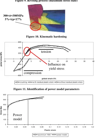
Before performing this kind of complex crash study it is necessary to characterised the rivets macroscopic behaviour (non-linear behaviour, failure criterion) [2]. Indeed, airframes are built with numerous rivets which influence the ruin mechanisms in case of crash [3], but it is impossible for obvious reasons of computing costs to refine the mesh at the rivet geometrical level in airframe models [4]. For this reason, thin simulations of rivets under mixed mode loading are previously undertaken and lead to the determination of different parameters for simplified link models (equivalent elements proposed by FE codes) [5]. To compute this kind of thin simulations, the behaviour of the crushed rivets material must be known up to failure (eg. Gürson damage model). Previous works have shown the high plastic strain level which develops in rivets during the forming process (εp from 5% up to 17% [6]). This is the
reason why it is proposed to characterise the effect of this first loading (riveting process) on rivet material, to be used in simulation (and more particularly the use on kinematic or isotropic hardening).
For that purpose, it is proposed to develop a new experimental characterisation technique which consists in doing micro-tension tests : indeed the size of rivets, which are about 8 mm long, raises problems considering classical characterisation techniques. First, it is impossible to use a normalised tension test specimen (l=5.65√S). Second, the geometry of the test specimen must be specifically designed for this kind of application. Third, it is necessary to use and adapt micro-gauge to measure the strains. As a first step, numerical tools help to select the geometry of the test specimen. Then the experimental investigation is divided in two steps. A first validation of the experimental procedure is presented by comparing test results with classical available ones on AU4G-T4 aluminium alloy. Then other tests are performed on “ on the shelf rivet ” extracted test specimens. Both results permit to undertake an identification of damage parameters of Gürson’s model with an inverse method (optimiser coupled to FE code Pam-solidTM [7]).
2. DESIGN OF TEST SPECIMENS GEOMETRY
2.1 GEOMETRICAL CONSTRAINTS
In the present case, the aim is to extract a test specimen from the rivet itself (small size of the rivet). The raw material available to manufacture the test specimen is a 4 mm diameter and 8.2 mm long cylinder. A test specimen is usually designed with two different parts. A working part where the material behaviour is captured (elasticity, plasticity, damage) during the loading phase. A second one which permits to attach the test specimen to the tensile machine. Considering the very small size of the specimens, we must consider a third one, which is the area between the two previous ones, in which geometrical effects may amplify and interact with the working part behaviour [8]. The objective is to take care about and minimise local embrittlement and stress concentration phenomena in that area if necessary.
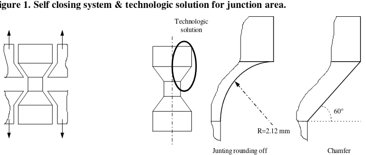
The final diameter of the working part of the specimen is chosen equal to 2 mm. Total length of test specimen is still 8.2 mm and it is proposed to use a working length of 1.5 mm. The final test specimen is shaped by turning process (better machined tolerance in this case). The grip system between the test facility and the specimen is a self-closing system (Figure 1).
Two shapes for the junction area are investigated (chamfer or junction rounding-off , see Figure 1). To check and choose between the two solutions, a F.E. code is used.
2.2 INFLUENCE OF THE JUNCTION AREA SHAPE
Both presented simulations are realised with an explicit FE code Pam-SolidTM. The nodal boundary conditions and the modelling simplifications are presented on Figure 2 (only 1/8th of the geometry is modelled). A rigid body is defined to model the massive parts (grip system). The master node of this rigid body is pulled by a rigid wall, the displacement of which is imposed by a velocity curve Vimp= f(t). The use of such a
rigid body gives access to the global load and displacement. In the first simulation, the junction area is a chamfer (α=60°). In the second, it is a junction rounding-off (r=2.12 mm).
The constitutive material law which is used is described as a power-model (hardening behaviour) coupled to the Gürson damage model (softening behaviour). Since the aim of this part of work is just to compare both specimen geometry response, Gürson damage parameters are taken from the literature [2].
Figure 3 shows the Von Mises stresses obtained in both simulations. Plastic strains are localised in the working part and no stress concentration phenomenon in the area of separation between working length and junction area is observed. Figure 4 gives the global load versus local strain. Finally the smallest deviation obtained between both curves shows that it is possible to take the simplest geometry for the specimens to be tested (chamfer instead of junction radius).
3. EXPERIMENTS
3.1 DESCRIPTION OF THE NEW PROCEDURE
Figure 5. Micro-gauges (L=0.5mm, h=0.38mm) are used and bonded in the working length area to measure directly the material deformation. This kind of micro-gauges can catch up to 20% strain levels before failure. The global load F is measured with a piezo-electric load cell (Kystler 9077). The displacement of the rigid rig is measured on the Schenck G-Nr 911 test facility sensor.
Quasi-static and dynamic tests performed on single lap riveted joint test specimens have highlighted no influence of strain rates on global behaviour and failure mode of the assembly (failure of 7050 aluminium rivet) [9]. As this step of the study, we will then consider for simplicity a quasi-static load velocity of Vimp =0.2mm/min.
To validate the experimental procedure and check if the specific geometry of the test specimens enables us to get intrinsic mechanical properties of the material, a first series of test specimens is realised in a well known aluminium AU4G-T4 [10].
3.2 TESTS RESULTS
3.2.1 AU4G-T4 aluminium alloy
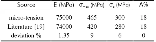
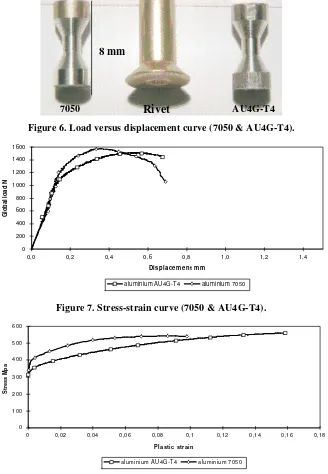
Results are presented in Table. 1 in terms of Young modulus, maximum and yield stress. Figure 6 shows the load versus displacement diagram for the AU4G-T4 aluminium alloy (the error linked to the setting of test specimens is corrected on the diagram). In fact the linear elastic behaviour is extrapolated on the basis of the measured behaviour between 0.07 and 0.1 mm of displacement). The obtained results show that AU4G-T4 aluminium alloy is slightly ductile. The local variables are presented on a stress-strain diagram in Figure 7 (real stress versus effective plastic strain). Global and local results show that the experimental procedure is validated in comparison with the literature for the AU4G-T4 aluminium alloy, except for the maximum stress which is known to be specimen sensitive.
Table. 1 Mechanical characteristics of AU4G-T4 aluminium alloy.
Source E (MPa) σmax (MPa) σe (MPa) Α%
micro-tension 75000 465 300 18
Literature [19] 74000 420 280 18
deviation % 1.35 9 6 0
3.2.2 7050 aluminium alloy
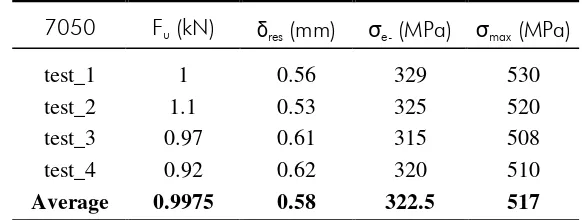
Results are presented in Table. 2 in terms of ultimate load and total displacement at failure (measured on test specimen after failure). The yield stress and the maximum stress σy and σmax are also reported in Table. 2. Figure 6 shows the load versus
Table. 2 Tests results (7050 aluminium alloy).
7050 Fu (kN) δres (mm) σe- (MPa) σmax (MPa)
test_1 1 0.56 329 530
test_2 1.1 0.53 325 520
test_3 0.97 0.61 315 508
test_4 0.92 0.62 320 510
Average 0.9975 0.58 322.5 517
3.3 SYNTHESIS
The micro-tension test has been used to characterise two aluminium alloys (7050 and AU4G-T4). The mechanical properties of the AU4G-T4 aluminium alloy obtained from the micro-tension tests enable to validate the experimental procedures. It proves its capacity to characterise constitutive material law for rivets in tension (or more generally small pieces).
The tests performed on 7050 aluminium alloy show the more ductile property of this aluminium. The obtained local results (stress-strain curve) permit to identify parameters of a power-model for εp<5% (with the assumption that no damage
develops for εp<5%). Only the load versus displacement diagram gives access to the
material behaviour up to failure (micro-gauges are limited to a 20 % deformation). Hence, the identification of Gürson’s model damage parameters is then undertaken on this response using an inverse method.
For a loading velocity of about 2mm/min the measured strain rates are in the order of magnitude of 0.02 s-1. So strain rates of about 600 s-1 (strain rate level interesting for crash scenarios) could be expected with this specimen geometry and loading velocities equal to 1m/s.
4. IDENTIFICATION OF GÜRSON MATERIAL MODEL
PARA-METERS [11-18]
4.1 OPTIMISATION TECHNIQUE
At a first run the optimisation procedure deals with the power-model parameters (σ = A+Bεp
n
). These parameters are computed for a range of deformation less than 5 % (no damage develops in this range). The identification is made with a direct method, taking 322.5 MPa as the yield stress A. The final values obtained for B and n are respectively 595 and 0.35 (Figure 11).
Where Np represents the number of experimental measurements of quantity ωexp. The load versus displacement response is used to perform the identification. The general identification method is based on physical considerations concerning the targeted parameters (chronology of events). So, at a first step, parameters εN, fN, SN
and fI are optimised. Then parameter fC, which is the critical void volume at
coalescence, and finally fF, which is the critical void fraction volume at ductile fracture,
are computed. Parameters qi concerns the micro-voids geometry. It proves to
influences the three steps of damage. The identification process is initialised by parameter vector z={q1, q2, fI, fN, SN, εN, fC, fF}={1.5, 1.5, 1E-17, 0.045, 0.075, 0.15,
0.045, 0.055} given in literature for the 7050 aluminium alloy [2]. Computing time is about 15 minutes on HP9000C100.
4.2 OPTIMISATION RESULTS
Finally, after 30 optimisation cycles, the parameter vector obtained is z={q1, q2, fI, fN,
SN, εN, fC, fF}={1.15, 1.5, 1 E-17
, 0.042, 0.075, 0.2, 0.165, 0.175}. Only the parameters q1, fN, εN, fC, and fF have changed. The reduction of q1 value means a more elliptic
micro-void geometry than initially.
The critical void volume at coalescence, fC, and the critical void fraction volume at
ductile fracture, fF, are more important than in the literature.
Figure 12 shows results in terms of loading versus displacement diagram and von Mises stress. Displacement at failure and maximum load are well predicted. Moreover the non linear behaviour is better apprehended with this newly identified model.
5. INFLUENCE OF RESIDUAL STRAINS ON GLOBAL LOAD
RESPONSE
5.1 EXPERIMENTAL PROCEDURE
To introduce residual strains of about 5% in the test specimen it is necessary to proceed in 3 steps :
• extract a cylinder (φ=4mm, h=8mm) of a 7050 aluminium rivet,
• crush the cylinder to reach εp=5%,
• machine a test specimen in the crushed cylinder.
The residual strain level of about 5 % corresponds to the mean level observed in 7050 aluminium rivet beam after being riveted, in respect with craft rules (see Figure 9) [20-21]. With this method, it is now possible to investigate the influence of residual strains on global material behaviour (F, δ). Results are given in a conventional diagram (A%,
σ=F/S0).
5.2 RIVETED MATERIAL DATA
Figure 10 compares results obtained with both experimental investigation (with and without residual stress in 7050 test specimens). In its natural state, the 7050 aluminium alloy has the same yield stress in tension and compression. The forming process modifies the tension characteristics of this aluminium as follows :
• mechanical characteristic decrease (σe0.2 = 200 MPa and σmax = 420 MPa),
• little influence on the hardening curve general shape,
The results as a whole prove that the hardening of the 7050 aluminium alloy is a kinematic one. This is mainly highlighted by the yield stress which decreases after one cycle of compression/tension. These results confirm the prediction made after ARCAN tests [5], for which the specimen strength was less than the simulated one (with an isotropic hardening model).
5.3 SYNTHESIS OF RESULTS
A residual plastic strain of about 5% is introduced in 7050 aluminium alloy test specimens. This strain level is the same as the one which can be measured in the core of rivets after the riveting process. The new test specimens (once crushed) present a yield stress of 200 MPa compared to 322.5 MPa for the natural rivet material state. The maximum stress decreases from 517 MPa down to 420 MPa. The experimental investigation shows the great influence of kinematic hardening on material behaviour and proves the need of kinematic hardening law in FE.codes.
6. CONCLUSION
An original micro-tension test technique is developed to give access to tensile constitutive material laws for small size pieces (eg. 8 mm long 7050 aluminium alloy rivets).
In a first step a validation of the experimental procedure is undertaken with well known AU4G-T4 aluminium alloy material based specimens. The obtained results (σy = 310 MPa, σmax = 477 MPa, A% = 18% et E = 75000 MPa) are compared with
the values available in the open literature. It shows no real influence of the test specimen geometry on the material law.
Micro-tension test specimens are then machined in the core of 7050 aluminium alloy rivets. Test results enable to find new parameters of the Gürson material law available in PAM-SOLIDTM F.E. code (elasto-plastic model coupled with damage model). In the one hand hardening parameters are computed with a direct method. In the other hand, parameters of Gürson’s damage model are reached using an inverse method (coupling an optimiser OPTB2L with Pam-SolidTM). The final vectors of parameter are :
• z = {A, B, n} = {310, 595, 0.35},
• z = {q1, q2, fI, fN, SN, εN, fC, fF} = {1.15, 1.5, 1E-17, 0.042, 0.075, 0.2, 0.165,
0.175}.
Other tests are then performed after having introduced a residual plastic strain state of about 5%. This strain level corresponds to the mean value measured in the core of 7050 aluminium alloy rivet after the riveting process. The new test specimens show a decrease of yield stress and maximum stress compared with material in natural neutral state. The experimental investigation proves that the hardening behaviour corresponds to a kinematic one which must be taken into account in F.E. material law used to simulate the riveted joints strength. The earlier development of damage may be the result of the natural embrittlement of material, due to irreversible evolution of microvoid geometrical characteristics (more elliptic).
It is then possible to describe the material behaviour as a coupled elasto-plastic damage model such as Gürson’s one. Before numerically characterising the static and dynamic strength of riveted joints (aluminium 7050) one should still :
• used a material law which takes into account kinematic hardening.
Under these two conditions, it will be possible to simulate correctly a riveted assembly and to evaluate the sensibility to the load velocity.
ACKNOWLEDGEMENT :
This research was carried out with an ONERA grant (operation number 99226). The authors are grateful to the ESI Group for the Pam-SolidTM FE code. The authors also wish to thanks the DASSAULT AVIATION Company.
BIBLIOGRAPHY :
[1] E. DELETOMBE,
"IMT CRASHWO RTHINESS FO R CO MMERCIAL AIRCRAFT - MO DÉLISATIO N PAR
ÉLÉMENTS FINIS DES ASSEMBLAG ES RO TULES PLASTIQ UES ET RUPTURE - RAPPO RT FINAL.", RAPPORT TECHNIQUE, ONERA - IMFL, N°96/25, MARS 1996.
[2] B. LANGRAND,
"CO NTRIBUTIO N A LA CARACTÉRISATIO N D’ASSEMBLAG ES RIVETÉS SO US SO LLICITATIO N
DYNAMIQ UE.",
THÈSE DE DOCTORAT, SEPTEMBRE 1998
[3] J. L. PETITNIOT, J. FABIS,
"CRASH SUR SITE - ETUDE DYNAMIQ UE D’UNE MAQ UETTE STRUCTURALEMENT
REPRÉSENTATIVE D’UN ÉLÉMENT DE FUSELAG E D’UN AVIO N DE TRANSPO RT.", NOTE TECHNIQUE, ONERA-IMFL N°84/48, NOVEMBRE 1983.
[4] E. DELETOMBE, B. MALHERBE,
"SIMPLIFICATIO N D’UN MO DÈLE DE CRASH D’AVIO N CO MPLET - RAPPO RT
FINAL.",
NOTE TECHNIQUE, ONERA-IMFL N°97/02, JANVIER 1997.
[5] L. PATRONELLI, E. MARKIEWICZ, B. LANGRAND, E. DELETOMBE, P.
DRAZETIC,
"ANALYSIS O F RIVET FAILURE UNDER MIXED MO DE LO ADING . ",
EJMEE, SOUMISE SEPTEMBRE 1999 ACCEPTÉE OCTOBRE 1999
[6] E. MARKIEWICZ, B. LANGRAND, E. DELETOMBE, P. DRAZETIC, L.
PATRONELLI,
"ANALYSIS O F RIVETING PRO CESS FO RMING MECHANISM. ",
INT. J. OF MATERIALS AND PRODUCT TECHNOLOGY, VOL .1313, NOS
[8] V. TVERGAARD AND A. NEEDLEMAN,
"ANALYSIS O F THE CUP-CO NE FRACTURE IN A RO UND TENSILE BAR.", ACTA METALLURGICA, 3232, PP. 157-169, 1984.
[9] B. LANGRAND,
"CARACTÉRISATIO N MATÉRIELLE D’UNE LIAISO N RIVETÉE.",
MÉCANIQUE INDUSTRIELLE ET MATÉRIAUX, VOL 51 N°2, PP. 76-79, 1998.
[10] PAR LES INGÉNIEURS DU GROUPE PÉCHINEY, "L’ALUMINIUM.",
[11] R. E. PETERSON,
"STRESS CO NCENTRATIO N FACTO R - CHARTS AND RELATIO NS USEFUL IN MAKING
STRENG TH CALCULATIO NS FO R MACHINE PARTS AND STRUCTURAL ELEMENTS.", A WILEY - INTERSCIENCE PUBLICATION, ISBN 0-471-68329-9.
[12] F. MONTHEILLET ET F. MOUSSY,
"PHYSIQ UE ET MÉCANIQ UE DE L'ENDO MMAG EMENT.", ÉDITIONS DE PHYSIQUE, 1988.
[13] F. MOUSSY,
"LES DIFFÉRENTES ÉCHELLES DU DÉVELO PPEMENT DE L'ENDO MMAG EMENT DANS LES
ACIERS, INFLUENCE SUR LA LO CALISATIO N DE LA DÉFO RMATIO N À L'ÉCHELLE MICRO SCO PIQ UE.",
PROC. CONSIDÈRE MEM. SYMP., SALENÇON J. ED., PRESSE DE L'ÉCOLE NATIONALE DES PONTS ET CHAUSSÉES, PP. 263-271, 1985.
[14] S. H. GOODS AND L. M. BROWN,
"THE NUCLEATIO N O F CAVITIES BY PLASTIC DEFO RMATIO N.", ACTA METALLURGICA, 2727, PP. 1-15, 1979.
[15] J. GURLAND,
"OBSERVATIO NS O N THE FRACTURE O F CEMENTITE PARTICLES IN A SPHERO IDIZED
1,05% C STEEL DEFO RMED AT RO O M TEMPERATURE.", ACTA METALLURGICA, 2020, PP. 735-741, 1972.
[16] A. S. ARGON AND J. IM,
"SEPARATIO N O F SECO ND PHASE PARTICLES IN SPHERO IDIZED 1045 STEEL, CU-0.6PCT
CR ALLO Y, AND MARAG ING STEEL IN PLASTIC STRAINING.", META. TRANS., 6A6A, PP. 839-851, 1975.
[17] G. ROUSSELIER, J. C. DEVAUX, G. MOTTET AND G. DEVESA,
"A METHO DO LO G Y FO R DUCTILE FRACTURE ANALYSIS BASED O N DAMAG E MECHANICS :
AN ILLUSTRATIO N O F A LO CAL APPRO ACH O F FRACTURE."
ASTM SPECIAL TECHNICAL PUBLICATION, 995995, PP. 332-354, 1988.
[18] J. C. DEVAUX, P. JOLY, AND J. B. LEBLOND,
"SIMULATIO N BY THE LO CAL APPRO ACH O F THE DUCTILE CRACK G RO WTH IN A PRESSURE
VESSEL STEEL USING AN IMPRO VED GURSO N TVERG AARD MO DEL.", 21ST MPA SEMINAR, 1995.
[19] F. LAURO,
"MÉTHO DO LO G IE PO UR LA PRISE EN CO MPTE DE L'ENDO MMAG EMENT
MICRO STRUCTURAL SO US CHARG EMENT DYNAMIQ UE.", THÈSE DE DOCTORAT, UNIVERSITÉ DE VALENCIENNES, 1996.
[20] MILTARY STANDARD,
"RIVETS, BUCK TYPE, PREPARATIO N FO R AND INSTALLATIO N O F.", US MILITARY STANDARD : MIL-R-47196A-NOTICE 1, 1986
[21] MILTARY STANDARD,
Figures
Figure 1. Self closing system & technologic solution for junction area.
Chamfer Junting rounding off
Technologic solution
R=2.12 mm
60°
Figure 2. Simplification and modelling (1/8th test specimen).
Rigid body Vimp Master node
Rigid wall
X Z
X Y
Figure 3. Influence of junction area on von Mises stress distribution.
rounding off
5 0 1 2 5 2 0 0 2 7 5 3 5 0 4 2 5 5 0 0 5 7 5 6 5 0
Chamfer Figure 4. Global load versus stress.
0 50 100 150 200 250 300 350 400
0.00 0.05 0.10 0.15 0.20 0.25 0.30 0.35
Strain
Global load N
Figure 5. Geometry of micro-tension test specimen.
Figure 6. Load versus displacement curve (7050 & AU4G-T4).
0 200 400 600 800 1000 1200 1400 1600
0,0 0,2 0,4 0,6 0,8 1,0 1,2 1,4
Dis p l a c e m e n t m m
Global load N
aluminium AU4G-T4 aluminium 7050
Figure 7. Stress-strain curve (7050 & AU4G-T4).
0 100 200 300 400 500 600
0 0,02 0,04 0,06 0,08 0,1 0,12 0,14 0,16 0,18
Plastic strain
Stress Mpa
aluminium AU4G-T4 aluminium 7050
Figure 8. Failure mode of 7050 aluminium alloy test specimen
7050 Rivet AU4G-T4
Figure 9. Riveting process (maximum stress state)
Figure 10. Kinematic hardening
-600 -400 -200 0 200 400 600
-10 -5 0 5 10 15 20 25 30 35 40
global strain A%
global stress MPa
crushing w ith residual plastic strain w ithout residual plastic strain
Figure 11. Identification of power model parameters
0 100 200 300 400 500 600
0 0,02 0,04 0,06 0,08 0,1 0,12 0,14 0,16 0,18 0,2
Plastic strain
Stress Mpa
aluminium 7050 power-model
Figure 12. Optimisation results (Load versus displacement and von Mises stress) Power
model
Influence on yield stress tension
compression 300<σσ<500MPa
0 200 400 600 800 1000 1200 1400 1600
0,0 0,2 0,4 0,6 0,8 1,0 1,2
displacement mm
Global loadt N
experiment open literature parameters new Gurson damage parameters