P
OWER FACTOR CORRECTION
1.INTRODUCTION
1.1 General ... 3
1.2 Power Factor ... 3
1.3 Reactive Power Demand ... 3
2.ECONOMIC EFFECT OF COMPENSATION
2.1 Procurement Cost of Compensation ... 3
2.1.1 Generation of Reactive Power by Means
of Rotating Machines ... 3
2.1.2 Procurement and Maintenance Cost
of Capacitors ... 3
2.2 Transmission of Reactive Power and
Design of the Network ... 4
2.3 Reactive Power and Transmission Losses ... 4
2.3.1
Active Power Losses ... 4
2.3.2 Reactive Power Losses ... 4
2.4 Reactive Power Transmission and
Voltage Drop ... 5
2.4.1 Parallel Compensation ... 5
2.4.2 Series Compensation ... 5
3.METHODS OF COMPENSATION
3.1 Individual Compensation ... 5
3.2 Group Compensation ... 6
3.3 Central Compensation at Low Voltage ... 6
3.4 High Voltage Compensation ... 7
3.5 Technical Consequences of Compensation ... 7
3.5.1 Voltage Rise ... 7
3.5.2 Influence of Harmonics ... 7
3.5.3 Ambient Conditions ... 8
4.COMPENSATION EQUIPMENT
4.1 Low Voltage Capacitors ... 8
4.1.1 Low Voltage Capacitor Units ... 8
4.1.2 Fixed Low Voltage Capacitor Banks ... 9
4.1.3 Automatically Controlled Low Voltage
Capacitor Banks ... 9
4.2 High Voltage Capacitors ... 9
4.2.1 High Voltage Capacitor Units ... 9
4.2.2 High Voltage Capacitor Banks ... 10
4.3 Protection of Capacitor Banks ... 10
4.3.1 Internal and External Fuses ... 10
4.3.2 Unbalance Protection ... 10
4.3.3 Overcurrent and overvoltage protection ... 10
4.4 Harmonic Filters ... 10
4.5 Fast Static Compensators ... 11
4.6 Thyristor Controlled Capacitors ... 11
2. ECONOMIC EFFECT OF COMPENSATION
1. INTRODUCTION
Fig. 1 The apparent power of a network can be reduced by means of power factor correction (PFC).
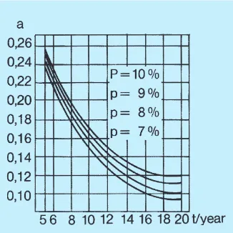
Fig. 2 Cost factor (a) derived from interest and depreciation.
1.1 General
In addition to active power most electrical devices also demand reactive power.
If this reactive power is not provided by capacitors in the immediate vicinity, it must be transmitted via the distribution system. In this case the influence of the reactive power on the total current must be taken into account when designing the system, and this can lead to a need for larger transformers and cables than would otherwise be necessary.
Moreover, transmission of reactive power causes additional energy losses. By means of reactive power compensation the amount of reactive power has only little significance in dimensioning the system and on transmission losses.
S1 = apparent power before PFC S2 = apparent power after PFC P = active power
Q1= reactive power before PFC Q2= reactive power after PFC
Qc= Q1–Q2 = compensation power of the capacitor
ϕ1 = phase angle before PFC
ϕ2 = phase angle after PFC
1.2 Power Factor
The total operating power, termed apparent power, can be expressed in terms of active and reactive power:
S = P2 + Q2 (1)
Power factor cos ϕ represents the following relationship between active and apparent power:
cos ϕ = P = active power
S apparent power (2)
Correspondingly
tan ϕ = Q = reactive power
P active power (3)
Power factor correction (PFC) means that capacitors (or synchronous machines) are used to reduce the amount of reactive power in electricity supplies to industrial and com-mercial consumers, thus improving the power factor to a higher value.
1.3 Reactive Power Demand
Induction motors need reactive power to main-tain the magnetic field essential for their op-eration. The average reactive power demand of asynchronous motors is approx. 1 kvar per 1 kW of active power.
Thyristor drives draw reactive current from the network and also generate harmonics which, among other things, tend to overload capacitors. In addition to the equipment men-tioned above, transformers, loaded cables, transmission lines and various electrical de-vices all need reactive power to some extent. Table 1. Examples of power factors
Load type Approximate
power factor (half ...full load) Induction motor <100 kW 0.6...0.8 250 kW 0.8...0.9
Thyristor drives 0.7
Incandescent lamp (glow) 1.0
Mercury arc lamp 0.5
Fluorescent lamp (hot cathode) 0.5...0.6
Neon tube lamp 0.4...0.5
Induction furnace 0.2...0.6
Arc furnace 0.6...0.8
Electric heater 1.0
AC arc or resistance welder 0.5...0.6
During recent years increasing attention has been paid to minimizing the energy costs and inefficiencies in electricity generation, trans-mission, distribution and consumption.
When designing a compensation scheme one should attempt to achieve the most eco-nomical solution, in which the savings achieved in equipment costs and transmission losses are significantly greater than the procurement cost of the reactive power.
When positioning capacitors note that unfavourable ambient conditions can shorten the life of the units, effectively incurring extra expense. The cost of installing capacitors, the effect of power factor correction on the volt-age level and the requirements of the electric-ity supply authorelectric-ity in regard to overcompen-sation, should also all be taken into account.
2.1 Procurement Cost of
Compensation
2.1.1 Generation of Reactive Power by Means of Rotating Machines
Traditionally, reactive power has usually been generated by rotating machines and trans-mitted through the system to consumers in the same way as active power. Large motors used in industry are often synchronous ma-chines which themselves generate the reac-tive power they need.
It is often possible to arrange for these machines to be overmagnetized and thus generate excess reactive power for compen-sation of other loads. The procurement cost of
the generators and synchronous machines depends on the desired extra amount of reac-tive power.
Generation of reactive power by synchro-nous machines incurs additional losses of 10...30 W/kvar, depending on the size and construction of the machine and the amount of reactive power generated. However, by raising the power factor, the additional losses can be reduced.
Reactive power produced by rotating machines must be transmitted through the distribution system. This leads to extra capital costs and additional transmission losses, which are especially significant at high volt-age transmission.
It is now generally accepted that it is not advantageous to install such generators and synchronous motors specifically for the pro-duction of large amounts of reactive power and also that it is often uneconomical to pro-duce reactive power from synchronous ma-chines that are already in the system.
This is a consequence of the rapid rise in energy prices in the 1970’s and from develop-ment in system capital costs when compared with the purchase and maintenance cost of capacitors.
2.1.2 Procurement and Maintenance Cost of Capacitors
The procurement cost of capacitors can, for economic comparisons, be expressed in an-nual costs as follows:
K = a . H (4)
K = annual cost
a = cost factor of interest and depreciation
H = procurement cost of capacitors including installation
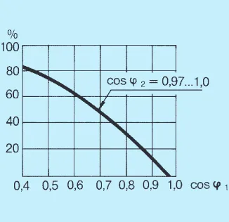
Fig. 3 Percentage degrease in design current of a network when the power factor (cosϕ2) is improved to near unity.
Fig. 4 Percentage decrease in total losses of a network with improvement in power factor.
Annual operating costs comprise losses, maintenance and repair costs. Power losses have now been drastically reduced since film has replaced paper as the dielectric material for capacitors.
Annual expenses for maintenance and repair are usually 1...2 % of the purchase price of the capacitor. Capacitor units have no moving or wearing parts. Contactors, regulat-ing relays in automatic capacitors banks and breakers in HV banks are the only compo-nents that require maintenance.
An investment in capacitors will normally be reimbursed in 0.5...2 years through lower losses and reactive power/energy charges. The annual savings for the whole depreciation period are 30...100 % of the purchase price.
2.2 Transmission of Reactive Power and Design of the Network
The total current in the network is, as a rule, the basic criteria for designing the system. At low voltage in particular, the thermal current of the network is the critical factor, whereas at high voltage other considerations, such as short circuit power, are also vital.
When parallel compensation is included in the system, less reactive power is transmitted. Hence the corresponding current component lq decreases, and consequently reduces the total current I which is expressed as follows: l = l2
p + l 2
q (5)
l = current having effect on the design of the network lp = current component caused by
active power transmission lq = current component caused by
reactive power transmission
Decreasing the current flowing in a new networks means that lower rated transform-ers, conductors and cables can be used. In an existing system more active power can be transmitted (lp increases) when the reactive power transmission is cut down (lq decreases) and the total load (l) remains constant.
By this means, replacement of the trans-former or cables can possibly be postponed for some years or to the end of working life. The power that can be transmitted through the same network can be calculated from: P2= P1 . cos ϕ2
cos ϕ1 (6)
P1 = transmission capability of active power of the network at power factor cos ϕ1
P2 = transmission capability of active power of the network at power factor cos ϕ2
2.3 Reactive Power and
Transmission Losses
Transmission of reactive power causes active power loss in network resistance and loss of reactive power in reactances.
Due to the former, such system compo-nents as cables and transformers experience a temperature rise, and the power loss (kW) and corresponding energy (kWh) have to be paid for.
2.3.1 Active Power Losses
Active power losses in a 3-phase network can be calculated from the following formula: Ph = 3 x l2 x R = 3 x l2
p x R + 3 x l 2
q x R (7) Ph = active power losses
R = resistance of the transmission network/phase
The above equation shows that power losses generated by the reactive current com-ponent (lq) are independent of the active power transmission and can be examined separately:
Phq = 3 x l2
q x R (8)
Note especially that power losses are in-curred in proportion to the square of lq, i.e. when the current rises 2-fold, losses will in-crease 4-fold. Correspondingly at a mean power factor of cosϕ = 0.7 for asynchronous motor load, half of the total transmission losses are due to the reactive power.
Resistance of cables can be roughly cal-culated from the formula:
R = k x 1
A (9)
R = cable resistance
k = 0.020 Ω x mm2/m for Cu-cables = 0.033 Ω x mm2/m for Al-cable l = cable length
A = cross section area of the cable Resistance of transformers may be calcu-lated as follows:
R = transformer resistance Sn = rated power of transformer U = supply voltage (by which the
resistance is calculated) rk = relative short-circuit resistance P1 = load losses at rated current (from
tables or rating plate)
When calculating losses, it is advisable to examine the various parts of the network sepa-rately. By this method the corresponding losses arising in cables, transformers etc. can be compared and the principal sources detected. This then becomes one criterion for the eco-nomical location of capacitors.
Annual costs of active power losses are: Ca = (Ph x a) + (Ph x ta x b) (12) Ca = annual cost of active power losses ta = time that active power losses are
being used a = power charge b = energy charge
If the power charge (or maximum demand charge) is not included in the tariff, the annual cost of loss energy is simply proportional to the length of time the equipment is used.
2.3.2 Reactive Power Losses
Losses caused by reactive power transmis-sion can be examined separately in the same way as active power losses. They are also independent of the active power transmis-sion.
3-phase reactive power losses can be calculated from the following formula: Qhq = 3 x l2
q x X (13)
Qhq = reactive power losses due to reactive current component X = network reactance
The reactance of an overhead line is calculated from its inductance:
X = 2 x π x f x L x l (14) X = line reactance
f = network frequency
L = specific inductance of the line l = length of the line
The reactance of overhead lines is generally of the order of 0.4 ohm/km which is consider-ably more than that of cables. Reactive power losses generated in cables are normally insig-nificant.
The transformer reactance is calculated as follows:
X = transformer reactance Sn = rated power of transformer U = supply voltage (at which reactance
is calculated)
zk = relative short-circuit impedance Xk = relative short-circuit reactance rk = relative short-circuit resistance
3. METHODS OF COMPENSATION
Fig. 5Parallel compensation reduces the voltage drop.
Fig. 6
Voltage may be raised to the desired level by means of a series capacitors.
2.4 Reactive Power
Transmission and Voltage Drop
2.4.1 Parallel CompensationTransmission of active power produces volt-age drop across the resistances in a network and reactive power transmission causes volt-age drop in the inductive reactances. The total voltage drop can be calculated approxi-mately from the following formula:
dU = lp x R + lq x X (17) dU = voltage drop (phase voltage) R = network resistance
X = network reactance
This shows that the voltage drop in the system reactances can be decreased by re-ducing the reactive current component, typi-cally by using parallel or, as it is also called, shunt compensation (Fig. 5).
With transformers, the voltage drop caused by transmission of reactive power is relatively high. This drop can be calculated from the following formula:
ud = l (rk x cosϕ + xk x sinϕ) (18) ln
ud = relative voltage drop in the transformer
cosϕ = power factor of load ln = rated current of transformer l = load current
2.4.2 Series Compensation
As previously stated, shunt compensation reduces the reactive component of the net-work current and, consequently, the voltage drop. With series compensation, the line re-actance is decreased by connecting capaci-tors in series with the line. The expression (17) for line voltage drop is then modified as follows:
dU = lp x R + lq x (Xl–Xc) (19) dU = voltage drop in the line
Xl = line reactance Xc = capacitor reactance
When Xc equals Xl, the network reactance is zero (Xl–Xc = 0) and the voltage drop caused by reactive power transmission is therefore also zero. By inclusion of a suitable series capacitor, Xc may be made greater than Xl, in which case the network reactance becomes negative. Thus, series compensation can also reduce the voltage drop caused by active power transmission (Fig. 6)
In addition, series capacitors provide the following advantages compared with uncom-pensated HV transmission systems: higher power transmission capability, better static and dynamic stability, fewer regulation requirements and reduced losses through optimizing load sharing in parallel lines. Series compensation is also a cost-saving alternative compared with building new, parallel lines.
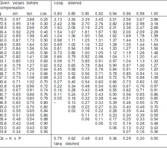
Table 2
Factor K for calculating the necessary compensation power for a given active power Given values before cosϕ desired
compensation
ϕ sin tan cos 0.80 0.85 0.90 0.92 0.94 0.96 0.98 1.00
75.5 0.97 3.88 0.25 3.13 3.26 3.39 3.45 3.51 3.58 3.67 3.88 72.5 0.95 3.18 0.30 2.42 2.56 2.70 2.76 2.82 2.89 2.98 3.18 69.5 0.94 2.68 0.35 1.93 2.06 2.19 2.25 2.31 2.38 2.47 2.68 66.4 0.92 2.29 0.40 1.54 1.67 1.81 1.87 1.93 2.00 2.09 2.29 63.2 0.89 1.98 0.45 1.24 1.36 1.50 1.56 1.62 1.69 1.78 1.99 60.0 0.87 1.73 0.50 0.98 1.11 1.25 1.31 1.37 1.44 1.53 1.73 58.6 0.85 1.64 0.52 0.89 1.02 1.16 1.22 1.28 1.35 1.44 1.64 57.3 0.84 1.56 0.54 0.81 0.94 1.08 1.14 1.20 1.27 1.36 1.56 56.0 0.83 1.45 0.56 0.73 0.86 1.00 1.05 1.12 1.19 1.28 1.48 54.7 0.82 1.41 0.58 0.66 0.79 0.92 0.98 1.04 1.11 1.20 1.41 53.1 0.80 1.33 0.60 0.58 0.71 0.85 0.91 0.97 1.04 1.13 1.33 51.8 0.79 1.27 0.62 0.52 0.65 0.78 0.84 0.90 0.97 1.06 1.27 50.2 0.77 1.20 0.64 0.45 0.58 0.72 0.78 0.84 0.91 1.00 1.20 48.7 0.75 1.14 0.66 0.39 0.52 0.56 0.71 0.78 0.85 0.94 1.14 47.3 0.73 1.08 0.68 0.33 0.46 0.60 0.65 0.72 0.79 0.88 1.08 45.6 0.71 1.02 0.70 0.27 0.40 0.54 0.60 0.66 0.73 0.82 1.02 43.8 0.69 0.96 0.72 0.22 0.34 0.48 0.54 0.60 0.67 0.76 0.97 42.3 0.67 0.91 0.74 0.16 0.28 0.43 0.48 0.55 0.62 0.71 0.91 40.7 0.65 0.86 0.76 0.11 0.24 0.37 0.43 0.50 0.56 0.65 0.86 38.7 0.63 0.80 0.78 0.05 0.18 0.32 0.38 0.44 0.51 0.60 0.80
36.9 0.60 0.75 0.80 – 0.13 0.27 0.33 0.39 0.46 0.55 0.75
35.0 0.57 0.70 0.82 0.08 0.22 0.27 0.33 0.40 0.49 0.70
33.0 0.55 0.65 0.84 0.03 0.16 0.22 0.28 0.35 0.44 0.65
30.5 0.51 0.59 0.86 0.11 0.17 0.23 0.30 0.39 0.59
28.4 0.48 0.54 0.88 0.06 0.11 0.17 0.25 0.33 0.54
25.6 0.43 0.48 0.90 0.06 0.12 0.19 0.28 0.48
23.0 0.40 0.43 0.92 0.06 0.13 0.22 0.43
19.8 0.34 0.36 0.94 0.07 0.16 0.36
Qc = K x P 0.75 0.62 0.48 0.43 0.36 0.29 0.20 0.00
tanϕ desired
Example: What is the capacitor power rating needed to improve the power factor from 0.66 to 0.98, if the active power requirement of the load is 750 kW?
From the above table the cross-reading gives K = 0.94.
The capacitor power rating should thus be 0.94 x 750 = 705 kvar. The nearest standard rating is 700 kvar, which can be selected.
When selecting the method of compensation required one should consider the location of the capacitors, the economic aspects re-ferred to above such as tariffs, the param-eters of the network, transmission losses and voltage drop, as well as the initial purchase cost and maintenance expenses of the equip-ment. In addition, there are factors such as system harmonics and the ambient condi-tions which may limit the effective utilization of capacitors.
Tables and nomograms are available to assist in calculating the capacitor rating re-quired. In table 2 the cross-reading of given and desired values of cosϕ or tanϕ gives the factor K, by which the active power P shall be multiplied. This yields the capacitor rating to be chosen.
There is no single method of compensa-tion to be recommended universally; various methods can be applicable in each case.
In the following three methods or parallel compensation will be discussed: individual, group and central compensation.
3.1 Individual Compensation
By connecting the capacitors to the termi-nals of the compensated equipment, one can best consider the influence of the ca-pacitors on the network dimensioning and on power and voltage losses.
Fig. 7 Principle of individual motor compensa-tion.
Fig. 8
Connection of a capacitor for a motor with a mechanical Y/D starter.
Fig. 9 Compensation of a group of motors. The motor M3 is always on whenever the mo-tor group is running.
Fig. 10 Connection scheme comprising fixed capacitors and automatically controlled ca-pacitor bank.
The necessary capacitor rating may be cal-culated from the formula:
Qc = P x (tanϕ1 – tanϕ2) (20) e
Qc = capacitor output P = rated power of motor e = efficiency of motor
ϕ1 = phase angle before PFC
ϕ2 = phase angle after PFC
A voltage rise caused by self-excitation can occur particularly when the motor is quickly re-connected immediately after switching off. It is therefore advisable to limit the compensa-tion power to:
Qc = 0.9 x l0 x U x 3 (21) l0 = no-load current of the motor
U = supply voltage
Because of self-excitation, it is not recom-mended to use individual motor compensa-tion if the machine driven by the motor can in turn rotate it at overspeed (cranes, carriers, etc.) or if the brake magnet voltage is derived from the poles of the motor.
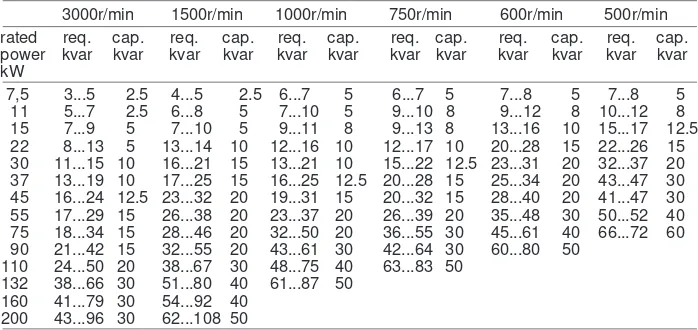
Table 3. Reactive power requirement of various squirrel-cage motors at no-load... rated power and the nearest standard capacitor rating, when the compensation power limitations have been taken into account.
3000r/min 1500r/min 1000r/min 750r/min 600r/min 500r/min rated req. cap. req. cap. req. cap. req. cap. req. cap. req. cap. power kvar kvar kvar kvar kvar kvar kvar kvar kvar kvar kvar kvar kW
7,5 3...5 2.5 4...5 2.5 6...7 5 6...7 5 7...8 5 7...8 5 11 5...7 2.5 6...8 5 7...10 5 9...10 8 9...12 8 10...12 8 15 7...9 5 7...10 5 9...11 8 9...13 8 13...16 10 15...17 12.5 22 8...13 5 13...14 10 12...16 10 12...17 10 20...28 15 22...26 15 30 11...15 10 16...21 15 13...21 10 15...22 12.5 23...31 20 32...37 20 37 13...19 10 17...25 15 16...25 12.5 20...28 15 25...34 20 43...47 30 45 16...24 12.5 23...32 20 19...31 15 20...32 15 28...40 20 41...47 30 55 17...29 15 26...38 20 23...37 20 26...39 20 35...48 30 50...52 40 75 18...34 15 28...46 20 32...50 20 36...55 30 45...61 40 66...72 60 90 21...42 15 32...55 20 43...61 30 42...64 30 60...80 50
110 24...50 20 38...67 30 48...75 40 63...83 50 132 38...66 30 51...80 40 61...87 50
160 41...79 30 54...92 40 200 43...96 30 62...108 50
When dimensioning the capacitor cable note that the fuses also protect the supply cable. Thus the capacitor cable shoud have the same cross-section as that of the main motor cable.
Also when setting any overcurrent relay, notice that the compensation reduces the current.
If the motor is equipped with an automatic star-delta starter where the motor is switched off directly from the delta configuration, a normally connected capacitor may be used for power factor correction.
However, if a mechanical star-delta starter is used as in Fig. 8, capacitors that are specifi-cally designed for this purpose must be fitted. Single-phase capacitors are connected in parallel with each winding of the motor.
3.2 Group Compensation
Sometimes it is possible to correct the power factor of several loads by means of a common capacitor. This kind of group compensation is particularly advantageous for discharge lamps controlled by 3-phase contactors. Group com-pensation of motors is also feasible where the motors are small or running simultaneously.
When a capacitor is connected into the network with a separate contactor, overvoltage due to self-excitation cannot occur. Thus the capacitor size can be chosen freely. The capacitor rating needed for cosϕ = 1 may be calculated from the following formula:
Q = P1 . tanϕ 1 +
P2
. tanϕ2 + ... (22) e1 e1
P1, P2... = rated power of the motors e1, e2... = efficiency of the motors
ϕ1, ϕ2... = phase angles before PFC Group compensation may often be advan-tageously applied when a standby motor is installed, thus avoiding duplication of capaci-tors.
3.3 Central Compensation at
Low Voltage
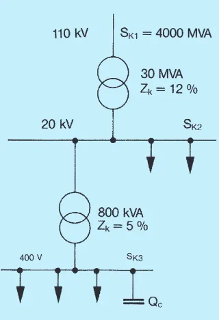
Fig. 11 Schematic diagram of the example.
Capacitors that are permanently connected to the system are continuously producing re-active power, even at periods of low load. Thus, any excess reactive power is trans-ferred into the main supply network.
Reactive power consumption of a distribu-tion transformer at no-load is 1...2 % and at full load 4...7 % of its rated power (see table 4).
To avoid the disadvantages of overcom-pensation, the total power of the fixed capaci-tors should be limited to 10...15 % of the transformer rating. A fuse switch or circuit breaker is generally fitted, so that the capaci-tor may be switched off if required.
Table 4. Approximate reactive power consumpiton of various 50 Hz distribution transformers (primary voltage 10...20 kV) Power Reactive power consumption
rating kvar
kVA no-load full load
16 0.3 1.0
In an automatic capacitor bank, a power factor controller controls the switching of the capacitor steps according to the varying re-active power requirements. Inductive and ca-pacitive operating limits for the power factor controller are set and the amount of reactive power in the network is maintained within these limits. Problems of overcompensation therefore do not arise.
The effects of central compensation on the dimensioning of a network and on the losses are mainly related to the distribution trans-former and the connecting cable. The elec-tricity board system can therefore benefit from low voltage power factor correction, and this is usually taken into account when connection charges and annual tariffs are determined.
3.4 High Voltage Compensation
Compensation may also be carried out on the high voltage side, in which case there are no cost savings related to the dimensioning and losses of the distribution transformers. Be-cause of the high reactance of transformers, considerable voltage drops and reactive power losses are also incurred by reactive power transmission. Thus, compared with LV com-pensation, more capacitors would be needed on the HV side of a transformer.
It is possible to compensate HV motors individually in the same way as with low volt-age. For this purpose enclosed capacitor banks are manufactured, which can then, if required, be installed adjacent to the motor.
Generally HV capacitor banks are used to compensate for the reactive power consumed by long transmission lines and power trans-formers. Sometimes it is economical to com-pensate for part of the reactive power of a large industrial plant by means of HV capaci-tor banks.
However, because of the relatively high c ost of the c onnec ting eq uip ment (viz: circuitbreaker, protection, cables, busbar), the total cost per kvar may seem unreason-ably high if compared with straightforward HV capacitor banks.
3.5 Technical Consequences of
Compensation
3.5.1 Voltage Rise
Fixed capacitors can cause the voltage to rise in an unloaded network. The rise in a trans-former on no-load may be calculated from the following formula:
du (%) = Qc . X k (%)
Sn (23)
du = percentage voltage rise Qc = rated power of capacitor bank Sn = rated power of transformer xk = percentage short circuit reactance
of transformer
In practice voltage rises of 1...2 % are experienced during no-load operation.
If, for example, the proportion of fixed capacitors is 20 % of the rated power of the transformer and xk = 6 %, the voltage of the transformer rises 1.2 % during no-load opera-tion.
3.5.2 Influence of Harmonics
Non-linear loads, such as thyristor drives, converters and arc furnaces produce exces-sive harmonic currents causing both current and voltage distortion. Capacitors offer a low impedance to any higher frequencies flowing through them, but they also may amplify the effect of harmonic currents flowing into other parts of the network.
The effect of harmonics on the phase voltage of a capacitor bank can be calculated from the following formula:
Up = ∑ lcn
n . 2 . π . f1 . C (24) Up = phase voltage of capacitor bank n = order of harmonic (the harmonic
frequency fn = n . basic frequency) lcn = ‘n’th harmonic current flowing
into capacitor bank
f1 = basic frequency (e.g. 50 Hz) C = capacitance of bank per phase
In other words, the voltage component of each harmonic is summed arithmetically at the basic frequency voltage. When designing a compensation scheme, the harmonics flow-ing into the bank must be calculated on the basis of the harmonic current imposed by the load. The harmonics in an existing capacitor bank can be measured by a harmonic ana-lyser.
The harmonics flowing into the capacitor bank can in some circumstances be very high. The worst situation arises when the ca-pacitors and the network inductance form a parallel or series resonant circuit under the following conditions:
n = Xc = Sk
Xl Qc (25) Xc = capacitive reactance of bank at
basic frequency
Xl = inductive short circuit reactance of network at basic frequency Qc = reactive power of capacitor bank Sk = short circuit power of network
Connecting a harmonic source and ca-pacitors to the same busbar could create a parallel resonant circuit. Similarly a capacitor bank connected to the LV side of a tranformer can form a series resonant circuit with the transformer for harmonics originating on the HV side. When carrying out reactive power compensation, one should avoid the danger
of resonance at any of the common orders of harmonics (viz: 3rd, 5th, 7th, 11th and 13th). The capacitor rating which could cause resonance if connected to the network, can be calculated for each harmonic as follows: Qc =
Sk
n2 (26)
For example, if the short-circuit power of the busbar is 15 MVA the equation (26) yields for n=3: Qc = 15 Mvar = 1.7 Mvar
For higher harmonics the possibility of resonance is generally slight but it must be taken into account if the harmonic content is very high.
The rated current of the thyristor drive system shown in Fig. 11 is calculated by using a power factor of 0.7, a diversity factor of 0.8 and motor efficiency of 95 % as follows: l = P = 0.8 . 3 . 100000
3 . U . e . cosϕ 3 . 380 . 0.95 . 0.7 = 550 A
The harmonics caused by thyristor drives are usually generated by 6-pulse rectifiers in the following percentages of rated current: 5th harmonic (30 %):
l5 = 0.3 . 550 A = 165 A 7th harmonic (12 %):
l7 = 0.12 . 550 A = 66 A 11th harmonic (6 %):
l11 = 0.06 . 550 A = 33 A 13th harmonic (5 %):
Fig. 12
Low voltage capacitor units
4.1 Low Voltage Capacitors
4.1.1 Low Voltage Capacitor UnitsA low voltage capacitor unit is built up of several elements connected in parallel. An element consists in principle of two electro-des and dielectric. The elements are made of metallized plastic film and inserted into a plastic cover.
Unlike capacitors made of aluminium foil or metallized paper, metallized-film capaci-tors are generally dry without impregnation liguid.
The elements of metallized-film capaci-tors are self-healing. After a disruptive discharge, a thin metallized layer will vapori-ze off from the surface around the breakdown point, and no permanent short-circuit will be left there. Elements are internally protected to ensure a reliable disconnecting at the end of the lifecycle.
Elements are set into a steel container and connected to the terminals of the capaci-tor by means of copper busbars and cables. Capacitor losses are very low, less than 0.5 watt per kvar.
Most low voltage capacitors are equip-ped with external discharge resistors so as to decrease the residual voltage of the capaci-tor from an initial value of √2 times the rated voltage Un to below the level of ≤ 50 V within 1 minute.
Low voltage capacitors are normally three-phase with three bushings on the cover and star or delta connected internally.
Among the unit sizes available for the most common voltage range 400...690 V are 2.5, 5, 7.5, 10, 12.5, 15, 20, 25, 30, 40, 50, 60, 75, 90 and 100 kvar, and the capacitance tolerance is -5...+10 %.
3.5.3 Ambient Conditions
Unfavourable conditions will shorten the life of a capacitor and thus incur extra repair and maintenance costs.
The temperature categories according to the new IEC standards for power capaci-tors cover the temperature range of -50 °C to +55 °C. For example, the highest permissible mean ambient temperature according to cate-gory A is +40 °C for a short period but only +30 °C for 24 h and +20 °C for 1 year. Higher temperatures accelerate ageing of the die-lectric, thus shortening the life of the capaci-tor. Power factor controllers for automatically controlled capacitor banks are usually made for an ambient temperature range of 0 °C to +50 °C.
In high humidity conditions outdoor type capacitor units should be used since they are suitably protected against corrosion.
4. COMPENSATION EQUIPMENT
The capacitance and reactance (at power frequency) of a 200 kvar capacitor bank are C = Qc = 200000 = 3.98 . 10-3 F
If the network impedance is simplified, consisting of only inductive reactance, it can be expressed as
Xk = U2 = 4002 = 0.01067 Ω Sk 15 . 106
At ’n’th harmonic frequency the reactances of the capacitor bank and network are
Xcn = Xc (27)
n
Xkn = n . Xk (28)
Xcn = capacitive reactance of the bank at ’n’th harmonic frequency Xc = capacitive reactive of the bank
at basic frequency Xkn = inductive reactance of the
network at ’n’th harmonic Xk = inductive reactance of the
network at basic frequency
The harmonic currents flowing into the bank (lcn) and into the network (lkn) are calcu-lated simply by using the current division rule when the currents of the harmonic source (ln) are known:
For the 5th harmonic the following har-monic currents are produced:
Xk5 = 5 . 0.01067 = 0.0533
The harmonic voltages across the capaci-tor bank are
Un = lcn . Xcn (=lkn . Xkn) (31) For n = 5: U5 = 82 A . 0.16 Ω = 13 V The total voltage stress is:
U = 400V + 3 . U5 + 3 . U7 + 3 . U11 + 3 . U13
Excess current caused by harmonics in a capacitor bank is calculated in terms of the effective value of the current:
lc = lc12 + ...l
cn2 (32)
lc = total current in capacitor bank lc1 = current in capacitor bank at
basic frequency (50 Hz)
lc1 = Qc = 200 A = 289 A 3 . U 3 . 0.4
Table 5. Current and voltage values due to the example. The corresponding values are also given for other capacitor ratings.
Cap. lc1 lc5 lc7 lc11 lc13 lc
Table 5 shows, at all the chosen ratings, that the capacitors will operate at a
consider-able overvoltage. Note that a 100 kvar bank would be nearly in resonance at the 13th har-monic. The effective value of current in almost 2.5 times the rated value. The capacitors could not withstand this degree of extra stress. When the rating of capacitors in a system increases in proportion to the load, the danger of resonance is shifted toward the lower fre-quencies which generally have higher har-monic currents.
It is also noteworthy that the currents flow-ing into the network are considerably higher compared with those generated by the thyristor drives. However, in practice the above as-sumption that the impedance would be purely inductive is not valid. At higher frequencies harmonics are damped by the network resist-ance and resonresist-ances are not as likely as in this example.
The problems arising with harmonics are solved by using a harmonic filter as described later.
Fig. 13
Cubicle type automatic capacitor bank
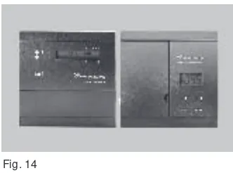
Fig. 14
Power factor controllers
Fig. 15
Automatic capacitor bank with blocking reactors
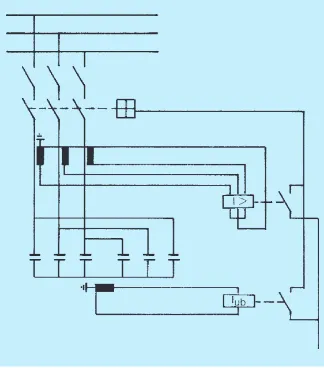
Fig. 16
Schematic diagram of an automatically controlled capacitor bank with power factor controller
Fig. 17
One-phase high voltage capacitor units
4.2 High Voltage Capacitors
4.2.1 High Voltage Capacitor UnitsOne-phase high voltage capacitor units are equipped with two bushings or one bushing with live case. Three-phase units are inter-nally either delta or star connected.
A capacitor unit consists of parallel and series connected elements. Series coupling is needed to keep the element voltage at a suitable level (about 2000 V).
The elements of modern HV capacitors are made of aluminium foil, separated by two or more layers of polypropylene film dielec-tric. Units with paper or mixed dielectric, commonly used before, have higher losses.
4.1.2 Fixed Low Voltage Capacitor Banks
Fixed capacitor banks consist of parallel con-nected units installed in a rack. The bank is fitted with a cable connection box. The ca-pacitance tolerance of a bank is –0...+10 %. Due to the large inrush current of a fixed bank, slow acting fuses dimensioned for 1.7 times the rated current must be used. Ac-cording to general standards, the connection cable must be able to carry a continuous load of 1.43 times rated current.
4.1.3 Automatically Controlled Low Voltage Capacitor Banks
Automatically controlled capacitor banks are equipped with fuses and contactors con-trolled by a power factor controller, on which a desired target value of power factor (cosϕ) and inductive and capacitive operating limits can be set.
The level of reactive power is monitored by means of current transformers and the power factor controller switches capacitors on and off according to demand.
A single step may comprise either one or several capacitor units; in the latter case the second unit is controlled via an auxiliary con-tact on the concon-tactor of the first unit and so on. In this way a time lag equal to the operating time of the contactor is introduced and the overall inrush current is thus reduced.
Steps can be equal or of different sizes, but if they are unequal the first (i.e. the small-est) determines the increment. The ratio of steps with respect to the first can be any of the following:
1:1:1:1:..., 1:2:2:2:..., 1:2:3:3:..., 1:2:3:4:... or 1:2:4:4:...
It is generally advisable to use standard banks with steps of, say, 50 kvar. With smaller banks, units of 25...30 kvar may be used for the first steps and with the smallest, units of even smaller power rating. Such arrange-ments are obviously more expensive per kvar than those comprising larger units.
Very large banks are usually divided into smaller subgroups, each with an individual connection cable and main fuses but with a common power factor controller.
The main fuses should be slow acting and dimensioned for 1.38 times rated current.
The capacitor elements are inserted into a steel container. The unit is then filled with a suitable, environmentally safe impregnation oil, and the containers are hermetically closed. HV units equipped with internal element fuses are manufactured up to 9000 V of rated voltage. Internal discharge resistors decrease the residual voltage from √2 x rated value to below 75 V within 10 minutes, according to IEC standards.
Fig. 18 Internally Externally
fused unit fused unit
Fig. 19
Schematic diagram of an HV capacitor bank connected in star with unbalance protection.
Fig. 20
Schematic diagram of an HV capacitor bank connected in double star with overload, short-circuit and unbalance protection.
Fig. 21
Typical filter construction.
4.2.2 High Voltage Capacitor Banks
High voltage capacitor banks are used at substations and in industry, on long transmis-sion lines, and at points in HV networks suit-able for maintaining reactive power balance. High voltage capacitor banks are usually built up of single-phase HV units, the required number in series depending on the voltage and the number in parallel, on the power.
In order to divide the voltage evenly, an equal number of units are connected in paral-lel in each series group. Series groups are separated from each other by support insula-tors mounted between the racks. Capacitor banks attached to a busbar are equipped with a breaker. If necessary, current limiting reac-tors can be supplied to reduce the inrush current to a value suitable for the breaker.
The main purpose of shunt capacitor banks is to produce reactive power near enough to point of consumption in order to reduce losses, cut the price of reactive power, increase the voltage, and improve the power transmission capacity of the line section.
4.3 Protection of Capacitor
Banks
In electricity networks the purpose of all protection is to protect the equipment against overcurrents and overvoltages and to mini-mize the effect of these, considering the eco-nomical and technical restrictions and safety regulations.
Internal protection of a bank comprises either internal or external fuses and unbalance protection, whereas externally the bank is protected against overload, overvoltage and short-circuit.
4.3.1 Internal and External Fuses
There are two types of fuses used for capaci-tors, internal or external. When the reactive power of a capacitor unit was only a few kvar, the most natural method to protect the capaci-tor was with an external fuse, since in the case of a breakdown the lost reactive power was small. However, now that one capacitor ele-ment has a capacity of about the same value as a unit had previously it is reasonable to protect each separate element with an inter-nal fuse.
If the capacitor unit is protected with inter-nal fuses the lost reactive power in the case of a blown fuse is very low (approximately 2 % of a unit). Because of the low percentage power loss there is no need to replace the entire capacitor unit, hence preserving continuity of operation and saving replacement costs.
If the unit is protected with an external fuse the whole unit is lost and it is nearly always necessary to replace the faulty unit immedi-ately. It is, therefore, obvious that by using
internally fused units the need for spare units is much lower than by using external fuses.
4.3.2 Unbalance Protection
HV banks are usually wired in either single or double star. If the impedance of one phase changes with respect to the other two phases, the star point of the bank shifts. This occurs when element fuses in a capacitor are blown as a result of a disruptive discharge.
At the same time the voltage division within the bank is also changed. Hence, the bank must be switched off before the operation of the fuses would cause a voltage rise consid-erably above the permitted 10 % overvoltage.
Double pole insulated voltage transform-ers are used for unbalance protection of sin-gle star connected banks. The transformer primaries are connected in parallel with the phase banks and the secondaries form an open delta. The unbalance voltage gener-ated in the open delta operates the breaker through a voltage relay.
Where there is a sufficient number of par-allel connected units, it is advisable to con-nect the bank in double star. Unbalance pro-tection is then carried out by a current trans-former connected between the two star points, and an overcurrent relay (Fig. 20). The time settings are 5 s for alarm and 0.1 s for tripping.
By using internal fuses, a reliab le unbalance protection can be performed, pro-tecting the banks against any major damages during a fault operation of the network or the banks.
4.3.3 Overcurrent and overvoltage protection
Overload and short-circuit protection of an HV bank is normally carried out by means of current transformers and a two-step overcur-rent relay.
The capacitor bank is characteristically self-protective against switching and light-ning overvoltages because of its low imped-ance at high frequencies.
Overvoltage protection is therefore usu-ally included in the protection of other equip-ment. If separate overvoltage protection is required, the discharge capacity of the pro-tective device is of great significance. Some-times a tripping overvoltage protection is needed at power frequency during low-load periods.
4.4 Harmonic Filters
Harmonic filters provide another source of compensation. In a filter, a reactor is con-nected in series with a capacitor bank. With a suitable reactor inductance, the series circuit of capacitor and reactor forms a low imped-ance at a desired harmonic frequency. Thus, the major part of the harmonic current flows into the filter and not into the network.
At the same time the filter provides capaci-tive reaccapaci-tive power at the base frequency.
Among the problems caused by harmon-ics are interference to telecommunications, disturbances to the control and protection system of the network, malfunctioning of re-lays and dangerous overvoltages due to reso-nance. The extra losses that occur in cables, transformers, motors and generators are also of significance: they cause loss of energy and excess temperature rise in the equipment. The most frequently encountered and poten-tially harmful harmonics are the 5th and 7th, which are generated by 6-pulse rectifiers.
Harmonic filters can be connected to ei-ther LV or HV circuits. Where ei-there are several harmonic generating loads, each fed by a distribution transformer, it is often more eco-nomical to eliminate the harmonics by install-ing filters centrally at the HV busbar, rather than to have separate filter on the LV side of each transformer.
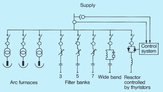
4.5 Fast Static Compensators
In some cases, for example arc furnaces and welding machines, there are very rapid fluctu-ations in reactive power within a short period – i.e. a few cycles. Traditional methods of re-active power control are not suitable since they are too slow for such variations.
The fast static compensator has been de-veloped to deal with this problem.
The Nokian Fast Static Compensator con-sist of a fixed shunt capacitor bank, normally tuned as a filter, and a thyristor-controlled shunt reactor. By controlling the reactor cur-rent, the total reactive power supplied by the f.s.c. into the network is correspondingly ad-justed.
Thus the harmonics generated both by the load and the thyristors are eliminated. Hence the disadvantages of fluctuations in reactive power and the harmonics are both minimized.
5. SUMMARY
Fig. 22Equivalent circuit of the harmonic filter and the network in accordance with Fig. 21.
Fig. 23
Impedance curves of the harmonic filter and other network in accordance with figures 21 and 22.
Fig. 24
Fast static compensator for arc furnaces.
The most economical way of producing reac-tive power required by most electrical devices is by the use of capacitors.
Capacitors reduce network losses and voltage drop, and the transmission of reactive power is avoided. This means considerable annual savings.
The circuit in Fig. 22 can be simplified further-more, consisting of parallel coupled network impedance Znw and filter impedance Zf. The impedance vary according to frequency as shown in Fig. 23 (absolute values). The cur-rents drawn consequently depend on them, and can be expressed as follows:
ln = Zf . l
n (33 a)
Znw + Zf
lf = Znw . l
n (33 b)
Znw + Zf
Static compensators are also used to re-duce voltage variations caused by power changes in transmission lines.
4.6 Thyristor Controlled
Capacitors
Thyristor controlled capacitors, which are more simple in construction than the fast static compensators described above, are very suitable for fast reactive power compensa-tion. The capacitor is equipped with a thyristor switch, which replaces the traditional contac-tor. Regulator operations are combined with the automatic thyristor controls. This equip-ment can rapidly compensate for fast reactive power fluctuations in welding machines and the consequent voltage variations.
By series capacitor bank, voltage may be raised to a desired level. Parallel capacitor banks can be used for individual, group or central compensation.
Harmonic Filters For High Voltage Detuned Filters
High Voltage Capacitor Banks
P
ri
n
te
d
i
n
F
in
la
n
d
b
y
H
e
rm
e
s
T
a
m
p
e
re
2
0
0
2
EN-TH01-11/2002 In line with our policy of on-going product development we reserve the right to
alter specifications
Kaapelikatu 3, P.O. Box 4, FIN-33331 Tampere, Finland Telephone +358 3 388 311, Telefax +358 3 3883 360
www.nokiancapacitors.com
Air-Core Reactors
Low Voltage Power Capacitors High Voltage Capacitors
Static Var Compensators (SVC) Series Capacitors