University of Zagreb
FACULTY OF MECHANICAL ENGINEERING AND NAVAL
ARCHITECTURE
Filip Putar
NUMERICAL MODELING OF DAMAGE
IN HETEROGENEOUS MATERIALS
USING STRAIN GRADIENT THEORY
DOCTORAL THESIS
University of Zagreb
FACULTY OF MECHANICAL ENGINEERING AND NAVAL
ARCHITECTURE
Filip Putar
NUMERICAL MODELING OF DAMAGE
IN HETEROGENEOUS MATERIALS
USING STRAIN GRADIENT THEORY
DOCTORAL THESIS
Supervisor:
Sveučilište u Zagrebu
FAKULTET STROJARSTVA I BRODOGRADNJE
Filip Putar
NUMERIČKO MODELIRANJE OŠTEĆENJA
U HETEROGENIM MATERIJALIMA
PRIMJENOM GRADIJENTNE
DEFORMACIJSKE TEORIJE
DOKTORSKI RAD
Mentor:
Prof. dr. sc. Jurica Sorić
Bibliography data
Bibliography data
UDC: 519.6 : 539.214 519.6 : 539.3 519.6 : 624.044
Keywords: quasi-brittle damage, C1 continuity finite element, strain gradient theory, multiscale analysis, RVE, heterogeneous material Scientific area: Technical Sciences
Scientific field: Mechanical Engineering
Institution: Faculty of Mechanical Engineering and Naval Architecture (FAMENA), University of Zagreb
Supervisor: Dr. sc. Jurica Sorić, Professor, University of Zagreb, Croatia Number of pages: 132
Number of pages (in total): 164 Number of pictures: 86
Number of tables: 6 Number of references: 148
Date of oral examination: 28 January 2019
Committee members: Dr. sc. Zdenko Tonković, Professor, University of Zagreb, Croatia
Dr. sc. Lovre Krstulović-Opara, Professor, University of Split, Croatia
Dr. sc. Marko Čanađija, Professor, University of Rijeka, Croatia
Archive: Faculty of Mechanical Engineering and Naval Architecture (FAMENA)
Acknowledgements
Acknowledgements
First of all, I would like to express my gratitude to my thesis advisor, prof. Jurica Sorić, for having accepted me as his PhD student and for the constant support, encouragement and guidance throughout the last four years. I would also like to thank prof. Zdenko Tonković for many valuable discussions and suggestions he generously offered during the research phase.
Furthermore, I would like to thank committee members profs. Lovre-Krstulović Opara and Marko Čanađija, for finding time to read and review this thesis, and for providing the valuable suggestions and comments that ultimately led to its improved version.
A special thanks to Tomislav Lesičar, who was basically my second advisor and a compass for scientific matters. Fruitful and stimulating discussions with him always got me back on track when I encountered challenges in the research.
I would like to express my gratitude to all my friends at the Faculty of Mechanical Engineering and Naval Architecture, particularly to my colleagues from the Institute of Applied Mechanics. I would like to thank the staff members of Laboratory of Numerical Mechanics, prof. Igor Karšaj and assist. profs. Tomislav Jarak and Ivica Skozrit, for all interesting polemics both related and unrelated to science. The pleasant and friendly work atmosphere made my office hours very enjoyable, and the best part of it were definitely cheerful meetings during the coffee and tea breaks which always managed to lift my spirits. A special thanks for that to my dear colleagues Lana Virag, Daria Ćurko, Marija Smoljkić, Boris Jalušić, Karlo Seleš, Ivan Trapić, Joško Frančeski, Matija Novak, Nino Horvat, Ante Jurčević, Josip Živić and Bruno Dogančić (no preferred order).
Finally, my deepest gratitude goes to my parents Jasna and Branko. Thank you for all your patience, understanding, unconditional support and believing in me when I needed it the most.
Thank you! Filip
Special acknowledgement
Special acknowledgement
I wish to express my sincere gratitude to the Croatian Science Foundation, which financed the research conducted in this thesis through the project “Multiscale numerical Modeling of Material Deformation Responses from Macro- to Nanolevel (2516)”.
Filip Putar Zagreb, November 2018
Contents
Contents
BIBLIOGRAPHY DATA ... I ACKNOWLEDGEMENTS ... II SPECIAL ACKNOWLEDGEMENT ... III CONTENTS ... IV LIST OF FIGURES ... VII LIST OF TABLES ... XIII NOMENCLATURE ... XIV ABSTRACT ... XVIII KEY WORDS ... XX KLJUČNE RIJEČI ... XX PROŠIRENI SAŽETAK ... XXI
1 INTRODUCTION ... 1
1.1 BACKGROUND AND MOTIVATION ... 1
1.2 OVERVIEW OF DAMAGE MODELING IN CONTINUUM ... 3
1.3 MULTISCALE MODELING OF DAMAGE ... 6
1.4 SCOPE AND OBJECTIVE ... 9
1.5 OUTLINE OF THE THESIS ... 11
2 DAMAGE MODELING IN LINEAR-ELASTIC MATERIALS ... 13
2.1 BASIC THEORY OF CONTINUUM DAMAGE MECHANICS ... 14
2.2 DAMAGE IN QUASI-BRITTLE MATERIALS ... 16
2.3 LOCAL APPROACH TO DAMAGE ... 20
Contents
3.1.1 Higher-order continuum theory ... 29
3.1.2 Formulation of the basic C1 continuity finite element ... 32
3.2 C1 CONTINUITY FINITE ELEMENT FOR SOFTENING ANALYSIS ... 34
3.2.1 Weak formulation ... 34
3.2.2 Calculation of constitutive stiffness matrices ... 37
3.2.3 Analysis procedure ... 40
3.3 NUMERICAL EXAMPLES ... 42
3.3.1 Plate with an imperfect zone subjected to tensile load, homogeneous microstructure ... 42
3.3.2 Plate with an imperfect zone subjected to tensile load, heterogeneous microstructure ... 50
3.3.3 Shear band problem ... 57
3.3.4 Compact tension specimen ... 64
3.3.5 Gear tooth damage ... 69
3.3.6 Discussion ... 71
4 MULTISCALE ANALYSIS OF QUASI-BRITTLE HETEROGENEOUS MATERIALS UNDERGOING DAMAGE ... 73
4.1 C1 CONTINUITY FINITE ELEMENT FOR SOFTENING ANALYSIS OF MICROSTRUCTURE ... 76
4.1.1 Weak formulation ... 76
4.1.2 Numerical test ... 78
4.2 C0-C1 MULTISCALE SCHEME ... 84
4.2.1 C0-C1 macro-micro scale transition relations ... 84
4.2.2 Numerical example ... 92
4.3 C1-C1 MULTISCALE SCHEME ... 96
4.3.1 C1-C1 macro-micro scale transition relations ... 96
4.3.2 RVE failure conditions ... 101
4.3.3 Numerical example ... 102
4.4 NUMERICAL EXAMPLES ... 103
4.4.1 Rectangular plate subjected to tensile load ... 103
4.4.2 Plate with an imperfect zone subjected to tensile load ... 110
4.4.3 Shear band problem ... 112
Contents
5 CONCLUSIONS ... 119
ŽIVOTOPIS ... 123
BIOGRAPHY ... 124
List of figures
List of figures
Figure 1.1 Homogenization of a heterogeneous material. Based on [60]. ... 8
Figure 2.1 Damaged body and RVE of the point M ... 15
Figure 2.2 Distribution of damage in a continuum. Based on [21]. ... 15
Figure 2.3 Evolution of the failure process in quasi-brittle materials. Based on [34]. ... 16
Figure 2.4 Damage growth and corresponding uniaxial stress-strain response for (a) linear softening and (b) exponential softening. Based on [6]. ... 18
Figure 2.5 Equivalent strain measurements in principal strain space for (a) Mazars’ definition (2.8) and (b) modified von Mises’ definition (2.9). Based on [6]. ... 19
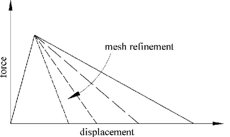
Figure 2.6 Qualitative softening responses for different finite element discretizations in the framework of classical continuum mechanics... 21
Figure 2.7 Representation of the nonlocal material behavior (top) and weighted averaging for an irregular microstructure (bottom). Based on [104]. ... 25
Figure 3.1C1 continuity triangular finite element. Based on [11]. ... 33
Figure 3.2 Scheme of the damage algorithm ... 42
Figure 3.3 Geometry and boundary conditions of the plate subjected to tensile load. Based on [45]. ... 43
Figure 3.4 Comparison of damage profiles along the horizontal central axis of the plate obtained using the presented FEM damage model to the EFG results from the literature... 44
Figure 3.5 The coarsest finite element mesh of the plate under tension ... 44
Figure 3.6 Comparison of damage profiles along horizontal central axis of the plate under tension for three different mesh densities ... 45
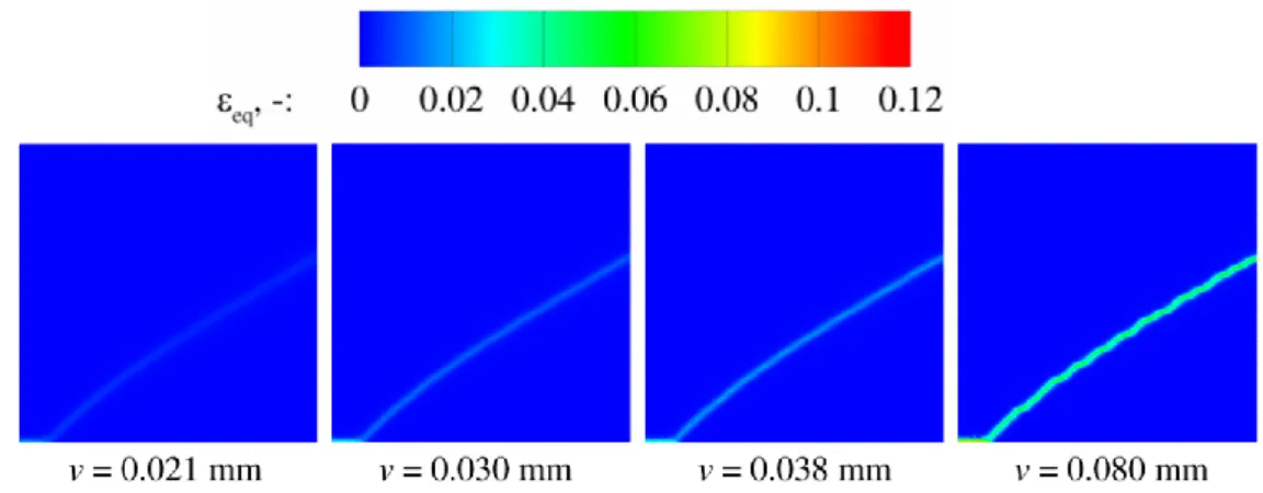
Figure 3.7 Evolution of the equivalent elastic strain eq along horizontal central axis of the plate for different loading levels ... 46
Figure 3.8 Evolution of the damage variable D along horizontal central axis of the plate for different loading levels ... 46
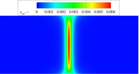
Figure 3.9 Distribution of the equivalent elastic strain eq for homogeneous material at failure stage ... 47
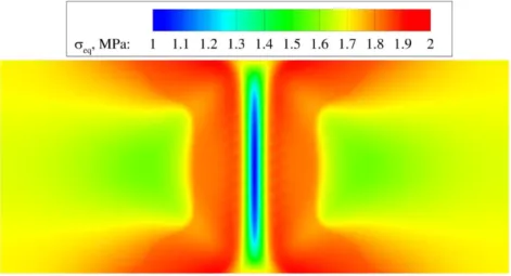
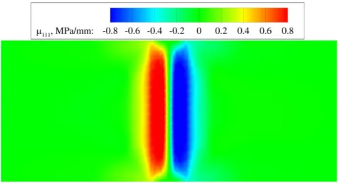
List of figures Figure 3.11 Distribution of the equivalent stress eq for homogeneous material at failure stage ... 48 Figure 3.12 Distribution of the strain gradient component 111 for homogeneous material at failure stage ... 49 Figure 3.13 Distribution of the double stress component 111 for homogeneous material at failure stage ... 49 Figure 3.14 Deformed shape with the distribution of strain component 11 for homogeneous material with the internal length scale l = 1.5 mm ... 50 Figure 3.15 RVE_0 described by the size L = 5.2 mm (l = 1.5 mm), average hole radius
ave 1.118
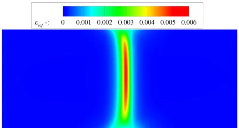
r mm and porosity e = 0.13 ... 51 Figure 3.16 Evolution of the equivalent elastic strain eq along horizontal central axis of the
heterogeneous plate for different loading levels ... 52 Figure 3.17 Evolution of the damage variable D along horizontal central axis of the heterogeneous plate for different loading levels ... 52 Figure 3.18 Distribution of the equivalent elastic strain eq for heterogeneous material
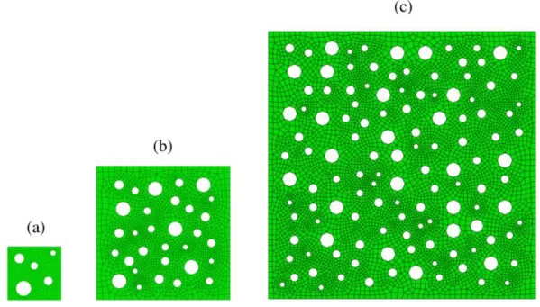
represented by RVE_0 at failure stage ... 53 Figure 3.19 Distribution of the damage D for heterogeneous material represented by RVE_0 at failure stage ... 53 Figure 3.20 Three different-sized samples of the same heterogeneous material: (a) RVE_1 with the size L = 3 mm (l = 0.87 mm), (b) RVE_2 with the size L = 7.5 mm (l = 2.16 mm) and (c) RVE_3 with the size L = 15 mm (l = 4.33 mm) ... 54 Figure 3.21 Comparison of damage profiles along horizontal central axis of the plate for heterogeneous material represented by three different-sized RVEs and homogenous material of the corresponding internal length scales ... 54 Figure 3.22 Comparison of damage profiles along horizontal central axis of the plate for two heterogeneous materials of the same porosity and corresponding homogenous material ... 55 Figure 3.23 RVE_4 described by the size L = 1.73 mm (l = 0.5 mm), average hole radius
ave 0.075
r mm and porosity e = 0.27 ... 56 Figure 3.24 Comparison of structural responses of the plate under tension for heterogeneous
List of figures Figure 3.25 (a) Geometry and boundary conditions of the plate with an imperfect zone subjected to compressive load (h = 60 mm) and (b) computational model consisting of upper half of the plate and appropriate boundary conditions, with a depicted mesh detail ... 58 Figure 3.26 Distribution of the equivalent elastic strain eq through several loading stages for homogeneous material ... 59 Figure 3.27 Distribution of the equivalent elastic strain e through several loading stages obtained by conventional implicit gradient formulation [33] ... 59 Figure 3.28 Distribution of the damage D through several loading stages for homogeneous material ... 60 Figure 3.29 Distribution of the damage through several loading stages obtained by conventional implicit gradient formulation [33] ... 60 Figure 3.30 Comparison of damage distribution D for homogeneous material for two different disretizations consisting of 800 (left) and 3200 (right) triangular finite elements ... 61 Figure 3.31 Comparison of damage distribution D for homogeneous material defined with the internal length scales l = 1 mm (left) and l = 2 mm (right) ... 61 Figure 3.32 Deformed shape with damage distribution D for homogeneous material with the internal length scale l = 2 mm ... 62 Figure 3.33 Distribution of the equivalent elastic strain eq through several loading stages for heterogeneous material ... 63 Figure 3.34 Comparison of structural responses of the plate under compression for heterogeneous material and homogeneous material of the same internal length scale ... 63 Figure 3.35 (a) Geometry and boundary conditions of the compact tension specimen (h = 100 mm) and (b) computational model consisting of upper half of the plate and appropriate boundary conditions ... 64 Figure 3.36 Damage evolution ahead of the notch tip through several loading stages obtained by (a) conventional implicit gradient damage formulation and (b) localizing gradient damage model with decreasing interactions [34] ... 65 Figure 3.37 Damage profiles at different loading stages obtained by conventional implicit gradient damage formulation [34] ... 66 Figure 3.38 Damage evolution ahead of the notch tip through several loading stages for homogeneous material ... 66 Figure 3.39 Comparison of damage distribution D for homogeneous material for two different disretizations consisting of 800 (left) and 3200 (right) triangular finite elements ... 67
List of figures Figure 3.40 Comparison of damage distribution D for homogeneous material defined with the
internal length scales l = 8 mm (left) and l = 20 mm (right) ... 67
Figure 3.41 Deformed shape with damage distribution D for homogeneous material with the internal length scale l = 8 mm ... 68
Figure 3.42 Comparison of structural responses of the compact tension specimen for heterogeneous material and homogeneous material of the same internal length scale ... 69
Figure 3.43 Computational model of the spur gear with: (a) notch and (b) pre-existing crack ... 70
Figure 3.44 Distribution of the equivalent elastic strain eq over the gear model with notch 71 Figure 3.45 Deformed shape with the distribution of the damage variable D over the gear model with pre-existing crack ... 71
Figure 4.1 Homogenization of the localized deformation ... 75
Figure 4.2 RVE of the side length of 0.5 mm discretized by 2205 C1 triangular finite elements ... 79
Figure 4.3 Tensile loading case: (a) computational model and (b) deformed shape with distribution of damage D in failure stage ... 80
Figure 4.4 Compressive loading case: (a) computational model and (b) deformed shape with distribution of damage D in failure stage ... 80
Figure 4.5 Shear loading case: (a) computational model and (b) deformed shape with distribution of damage D in failure stage ... 81
Figure 4.6 Structural responses for three different RVE loading cases ... 81
Figure 4.7 Structural responses for two tensile RVE loading cases with different internal length scale parameters ... 82
Figure 4.8 Distribution of the damage D through several loading stages for internal length scale parameter l = 0.01 mm ... 82
Figure 4.9 Distribution of the damage D through several loading stages for internal length scale parameter l = 0.02 mm ... 83
Figure 4.10 Scheme of C0-C1 multiscale algorithm ... 85
Figure 4.11 Representative volume element [17] ... 86
Figure 4.12 Geometry and boundary conditions of the plate subjected to tensile load... 93 0
List of figures Figure 4.15 Load-displacement diagrams obtained by three different macrolevel discretizations used in C0-C1 multiscale scheme and by one-scale damage model ... 96 Figure 4.16 Scheme of C1-C1 multiscale algorithm ... 97 Figure 4.17 Localization zone inside an RVE ... 101 Figure 4.18 Macrolevel discretization consisting of: (a) 48 and (b) 96 C1 continuity triangular finite elements ... 102 Figure 4.19 Load-displacement diagrams obtained by two different macrolevel discretizations used in C1-C1 multiscale scheme and by one-scale damage model ... 103 Figure 4.20 Computational model of rectangular plate subjected to tensile load with h = 10 mm ... 104 Figure 4.21 RVE described by the size L = 2.6 mm, average hole radius rave 0.559 mm and porosity e = 0.13 ... 105 Figure 4.22 Load-displacement diagram obtained by C1-C1 multiscale analysis for heterogeneous microstructure of internal length scale lmicro 0.6608 mm ... 105 Figure 4.23 Distribution of damage variable D over some characteristic RVEs for
micro 0.6608
l mm at failure stage ... 106 Figure 4.24 Load-displacement diagram obtained by C1-C1 multiscale analysis for heterogeneous microstructure of internal length scale lmicro 0.025 mm ... 107 Figure 4.25 Distribution of damage variable D over some characteristic RVEs for lmicro 0.025
mm at failure stage ... 108 Figure 4.26 Load-displacement diagrams obtained by one-scale damage models and C1-C1 multiscale scheme for materials consisting of homogeneous and heterogeneous microstructures ... 109 Figure 4.27 Structural responses of the plate subjected to tensile load obtained by the C1-C1 multiscale scheme for homogeneous and heterogeneous microstructure ... 111 Figure 4.28. Deformed shape with the distribution of strain component 11 for heterogeneous microstructure with the internal length scale lmicro 0.025 mm at final stage of the analysis ... 111 Figure 4.29 Distribution of damage variable D over some characteristic RVEs for lmicro 0.025
List of figures Figure 4.30 (a) Geometry and boundary conditions of the plate with an imperfect zone subjected to compressive load (h = 60 mm) and (b) discretization consisting of 96 C1 continuous triangular finite elements ... 113 Figure 4.31 Structural responses of the plate subjected to compressive load obtained by the C1 -C1 multiscale scheme for homogeneous and heterogeneous microstructure ... 114 Figure 4.32 Distribution of the equivalent elastic strain eq for heterogeneous microstructure with the internal length scale lmicro 0.025 mm at the onset of softening ... 115 Figure 4.33 Distribution of damage variable D over some characteristic RVEs for lmicro 0.025
List of tables
List of tables
Table 3.1 Basic relations of the strain gradient continuum [17] ... 31
Table 3.2 Basic relations of the second-order homogenization [17] ... 38
Table 3.3 Stiffness calculation for microstructurally homogeneous and heterogeneous materials ... 40
Table 4.1 Solving algorithm of C0-C1 macro-micro scheme ... 92
Table 4.2 Macro-to-micro scale transition relations in C1-C1 multiscale scheme [11] ... 98
Nomenclature
Nomenclature
Greek symbols
,
exponential softening law parameters
local variable nonlocal variable ε strain tensor 1, 2, 3 principal strains eq
equivalent elastic strain
eq
local equivalent elastic strain
eq
nonlocal equivalent elastic strain
1, 2
x x
ε ε strain gradient tensor
ε iterative correction of strain tensor
1, 2
x x
ε ε iterative correction of strain gradient tensor
δε strain tensor variation
3η second-order strain tensor
3
η iterative correction of second-order strain tensor
3
δ η second-order strain tensor variation
weight function
history parameter
0
initial history parameter
u
ultimate history parameter
first Lamé's elastic constant
1 2
3 3 3
, x, x
Nomenclature
second Lamé's elastic constant
gradient operator 2 Laplacian operator Poisson’s ratio , isoparametric coordinates
σ Cauchy stress tensor
1 i
σ Cauchy stress tensor at the last converged equilibrium state
σ iterative correction of Cauchy stress tensor
σ effective stress tensor
eq
equivalent stress
τ double surface traction tensor
Latin symbols
A surface of the body
d A localization area 1, ..., 21 a a displacement coefficients 1 2 , , ,
B B B B derivatives of the shape functions
eff
C effective stiffness tensor
C elastic stiffness tensor
4
,
C C material matrix relating stress to strain
5
,
C C material matrix relating stress to second-order strain
5
,
C C material matrix relating double stress to strain
6
,
C C material matrix relating double stress to second-order strain
1 2
4 5 5
, ,
x x
C C C generalized Aifantis material matrices
1 1 1 1 2
5 6 6
, ,
x x x x x
C C C generalized Aifantis material matrices
2 2 1 2 2
4 5 5
, ,
x x x x x
Nomenclature 1 2 , , c c c gradient coefficients D coordinate matrix D damage variable 1 i
D damage variable at the last converged equilibrium state
1 d d i D ε
derivative of damage variable over the strain tensor at the last converged equilibrium state
D
iterative correction of damage variable
D normal gradient operator
d phase-field parameter
e porosity
E Young’s modulus
e, i
F F external and internal nodal force vectors
b
f RVE boundary nodal force vector
c
G fracture energy
1, 2
H H coordinate matrices
h degradation function
I second-order unit tensor
1
I first invariant of strain tensor
2
J second invariant of deviatoric strain tensor
K finite element stiffness matrix
bb
K condensed RVE stiffness matrix
aa, ab, ba, bb
K K K K RVE stiffness submatrices
, , , K K K K stiffness submatrices 1 2 , , x x K K K stiffness submatrices
k ratio between uniaxial compressive and tensile strength
L RVE side length
Nomenclature
N, n unit outward normal vector
r microfluctuation field
s boundary line
T double traction tensor
t surface traction vector
u displacement vector
b
u RVE boundary displacement vector
1 i
u displacement vector at the last converged equilibrium state
u displacement vector variation
u iterative correction of displacement vector
u displacement field
V volume of body
V global vector of nodal degrees of freedom
V iterative correction of global vector of nodal degrees of freedom
v vector of nodal degrees of freedom
v variation of nodal degrees of freedom
v iterative correction of nodal degrees of freedom
W strain energy density function, work
x, y position vector
x, y Cartesian coordinates
1, 2
Abstract
Abstract
Prevention of the damage phenomenon in the structural components has always been a major criterion for keeping the longest possible working lifetime of the engineering systems and thus the minimization of the financial expenses due to maintenance, as well as for the safety of the people who benefit from such systems. In recent times, the need for keeping the track of the damage is even higher as a demand towards lighter, thinner and smaller designing solutions is rapidly increasing, where the very rigorous reliability and safety requirements need to be satisfied. In addition, new production technologies enable the manufacturing of the novel material solutions that provide exceptional exploitation characteristics, but can be very susceptible to failure due to very complex microstructures, where, from the engineering point of view, the initiation of the damage takes place. In order to reduce the amount of classical experiments to assess the structural integrity, various numerical models for the description of the material degradation are developed to this end. Due to importance of the microstructure in the damage development, multiscale models capable of consideration of such phenomena present an important modeling tool, but still need to be developed more for the commercial use. Regarding the modeling of damage at one scale only, classical continuum theory cannot be employed due to inconsistencies in the mathematical model that eventually lead to incorrect numerical results. Most of the available damage models take into account the influence of the microstructure by enhancing the constitutive relations with the measurement of the internal length scale, which serves as a strain localization limiter and prevents the dependency of the numerical results on the discretization. Although most of the models based on this, so called nonlocal continuum, can prevent the aforementioned numerical artefacts when damage is considered, there are still some difficulties that can arise when the internal length scale is kept constant, leading to nonphysical or spurious growth of the damage.
Herein, a damage model for quasi-brittle materials embedded into the two dimensional C1 continuity triangular finite element formulation based on the strain gradient continuum theory is considered. The isotropic damage law is applied to the higher-order stress-strain constitutive model, which enables the analysis of both homogeneous and heterogeneous
Abstract second-order homogenization procedure is applied to the various representative volume elements in the frame of a multiscale approach. The derived finite element formulation is implemented into the finite element program ABAQUS by means of UEL subroutine. The superior regularization capabilities, as well as the accuracy and efficiency of the proposed higher-order gradient damage model are demonstrated by the standard benchmark examples.
In the multiscale modeling of damage several obstacles are present of which still some have to be resolved, especially when computational homogenization is applied as a method for scale transitioning. Namely, generally a higher-order continuum has to be used at the macrolevel, while in the presence of the sharp localization zones at the microstructural level, macrostructural response is dependent on the size of the RVEs used. Physically, inconsistencies can arise in such conditions between the strain fields of two structural levels, which is known as the violation of the scale separation.
In the thesis, previously developed multiscale scheme which utilizes the higher-order continuum at both structural levels is modified for the consideration of the damage at the microlevel. Effects of the microlevel damage formation can be observed through the degradation of the homogenized tangent stiffness tensors, which then govern the localization at the larger structural level. Finite element based on the Aifantis theory of gradient elasticity is adapted for the softening analysis and its capabilities are tested on the random RVE for several different loading cases. Additionally, in order to prove the necessity for the higher-order continuum at the macroscale, which is in this case generalized Aifantis theory, scale transition methodology where classical continuum is employed at the macrolevel is developed. Therein, rather than strains and strain gradients, only the strain tensors contribute to the formation of the RVE boundary displacements, while the stiffness tensors that carry the nonlocal characteristics cannot be transferred at the macrolevel. Both multiscale schemes are tested on a standard benchmark example and compared with the one-scale damage model solution for the case of the homogenous microstructure, when only a mild and diffused localization is observed. In order to capture the loss of structural integrity of the macrostructural integration point when sharp localization is formed across an RVE, a specific conditions which detect the completely formed localization zone are developed. Finally, the capabilities of the presented C1-C1 multiscale scheme to capture the effects of the sharp localization at microlevel are demonstrated by few benchmark numerical examples.
Key words / Ključne riječi
Key words
quasi-brittle damage
C1 continuity finite element strain gradient theory multiscale analysis RVE
heterogeneous material
Ključne riječi
kvazi-krhko oštećenje
konačni element C1 kontinuiteta gradijentna deformacijska teorija višerazinska analiza
RVE
Prošireni sažetak
Prošireni sažetak
Uvod
Novi i sve stroži zahtjevi na pouzdanost i sigurnost konstrukcija, zajedno s primjenom novih materijala i novih proizvodnih tehnologija, mogu jedino biti ostvareni korištenjem naprednih metoda numeričke strukturne analize i što realnijim opisom ponašanja materijala. Budući da u radnom vijeku određene konstrukcijske komponente može doći do pojave oštećenja, potrebno je znati opisati njeno ponašanje sve do potpunog gubitka mehaničkog integriteta, odnosno loma. Većina inženjerskih materijala nakon određene deformacije počinje pokazivati postepeno smanjenje krutosti ili takozvano popuštanje što je direktna posljedica degradacijskih procesa na razini atomske rešetke. Kako je numeričko modeliranje procesa koji se zbivaju na toj razini još uvijek neprikladno sa stajališta računalnog vremena, oštećenje se u odgovarajući numerički algoritam najčešće uvodi kao set kontinuiranih makroskopskih varijabli koje nose informaciju o stanju materijala na nižim prostornim skalama, odnosno u njima je implicitno sadržano stanje mikrostrukture. Popuštanje se može istovremeno odvijati s pojavom plastičnosti što je slučaj kod duktilnih materijala kao što su razni čelici, a u slučaju izostanka plastičnosti govori se o popuštanju kvazi-krhkih materijala poput perlitne matrice u nodularnom lijevu koji se često javlja u mehaničkim konstrukcijama, betona, keramike i nekih vrsta ojačanih kompozita.
Oštećenje je u inženjerskim materijalima izrazito nehomogeno i lokalizirano. Mikropukotine se stvaraju na mjestima koncentracije naprezanja i njihov je naknadni rast u ograničenom području koje je malo u usporedbi sa cijelom konstrukcijskom komponentom. Pojava popuštanja koja nastaje kao posljedica oštećenja uvijek je popraćena velikim gradijentima deformacije na način da se deformacija lokalizira u području gdje se popuštanje odvija. U teoriji klasičnog kontinuuma popuštanje može dovesti do lokalnog gubitka eliptičnosti diferencijalnih jednadžbi koje opisuju proces deformiranja. Matematički gledano, modul materijalne tangentne krutosti pri ulasku u fazu popuštanju prestaje biti pozitivno definitan što rezultira lošom uvjetovanošću cjelokupnog problema, posljedica čega je nemogućnost konvergencije numeričkih rješenja prema fizikalno smislenom rješenju. Pritom se deformacija, promatrano u okviru metode konačnih elemenata, lokalizira u samo jedan konačni element ili najtanji sloj konačnih elemenata, a disipacijska energija teži k nuli.
Prošireni sažetak
Postojeći modeli oštećenja
Očuvanje eliptičnosti diferencijalnih jednadžbi koje opisuju proces deformiranja u fazi popuštanja, ili takozvana regularizacija problema lokalizacije deformacije, moguća je primjenom mehanike kontinuuma višeg reda. Njome se, za razliku od klasične mehanike kontinuuma, preko parametra unutarnje duljinske skale u obzir uzimaju i mikrostrukturne interakcije koje se mogu opisati na više različitih načina. Primjenom mikropolarne teorije ili poznatije Cosseratove teorije, materijalne čestice dobivaju dodatan rotacijski stupanj slobode neovisan o polju pomaka. Time se veoma uspješno rješavaju problemi gdje je smik dominantan način deformiranja tako da pri čistom vlaku pristup ne funkcionira. Viskoplastična teorija u konstitutivni model uključuje ovisnost brzine promjene deformacije, odnosno viskozne efekte, no ona daje dobre rezultate samo ako je lokalizacijska zona unaprijed poznata.
U novije vrijeme sve se češće primjenjuju metode temeljene na nelokalnom ponašanju materijala, tako da naprezanje u nekoj točki kontinuuma ne ovisi samo o deformaciji i ostalim varijablama stanja u toj točki, već i o deformacijama i ostalim varijablama stanja točaka koje ju okružuju. U osnovi razlikuju se dva različita pristupa pri opisivanju nelokalnog modela, integralni i gradijentni pristup. Integralni pristup temeljen je na prostornom osrednjavanju varijabli stanja, najčešće deformacija, u konačnoj blizini određene točke, što naposljetku dovodi do veoma složenih konstitutivnih relacija sastavljenih od integrala konvolucijskog tipa. Gradijentni pristup proširuje konstitutivnu relaciju ili samo gradijentima deformacije ili gradijentima deformacije i njihovim konjugiranim veličinama, što se odnosi na takozvanu punu gradijentnu teoriju. U slučaju proširenja samo gradijentima deformacije, do sada su kod proučavanja lokalizacije i popuštanja najčešće korištene implicitne i nešto rjeđe eksplicitne gradijentne formulacije. Problemi razmatrani u literaturi vezani su za elastično ponašanje materijala, plastično ponašanje materijala, ili se dotiču analize širenja elastičnih valova. Mišljenja su da eksplicitna gradijentna formulacija u model unosi takozvanu slabu nelokalnost budući da je ekvivalentna nelokalna deformacija izražena najčešće samo preko ekvivalentne lokalne deformacije i njenog drugog gradijenta, što proizlazi odbacivanjem viših članova razvoja lokalne ekvivalentne deformacije u Taylorov red. Implicitna formulacija s druge strane unosi takozvanu jaku nelokalnost jer kod nje nelokalna deformacija nije eksplicitno izražena
Prošireni sažetak implementaciji, pa tako korištenje eksplicitne formulacije zahtijeva uporabu konačnih elemenata C1 kontinuiteta, dok se implicitna formulacija najčešće rješava konačnim elementima C0kontinuiteta temeljenim na mješovitoj formulaciji. Iako su C0konačni elementi u osnovi jednostavniji od konačnih elemenata C1 kontinuiteta, upitno je postiže li se uvođenjem mješovite formulacije bolja numerička učinkovitost.
Usprkos tome što se implicitnom gradijentnom formulacijom mogu dobiti rješenja neovisna o gustoći i usmjerenju mreže, u literaturi je prijavljeno nekolika slučajeva u kojima dolazi do nefizikalnog širenja oštećenja po računalnom modelu. Opisana pojava karakteristična je i za integralne i za gradijentne pristupe klasičnog tipa, u kojima područje mikrostrukturnog međudjelovanja ostaje konstantno tijekom cijelog procesa opterećivanja. Kao što je objašnjeno u literaturi, navedena pretpostavka ima za posljedicu prijenos energije iz područja u kojoj se oštećenje odvija u susjedno područje koje elastično popušta. Na taj način dolazi do rasta oštećenja u područjima gdje ga fizikalno ne bi trebalo biti, te je onemogućeno stvaranje uskog pojasa lokalizacije deformacije. Problem je riješen uvođenjem modificiranih nelokalnih formulacija u kojima je veličina područja mikrostrukturnog djelovanja podložna promijeni tijekom procesa opterećivanja. Međutim, većina takvih formulacija opisuje povećanje navedenog područja s porastom oštećenja, što nije u skladu s fizikalnim procesom stvaranja makropukotine, gdje je situacija upravo suprotna, pogotovo u slučaju kvazi-krhkih materijala. Od nedavno sve više se razvija modeliranje putem takozvanog faznog polja, koje dijeli mnogo sličnosti s gradijentnim formulacijama po pitanju matematičke strukture. Iako se navedenim pristupom mogu dobiti u potpunosti regularizirana rješenja, kako bi se dobio točan razvoj faznog polja, odnosno oštećenja, potrebno je značajno povećati broj konačnih elemenata u području gdje se očekuje pojava pukotine, što naposljetku dovodi i do značajnog povećanja računalnog vremena.
Drugi tip gradijentnog pristupa gdje u funkciju energije deformiranja ulaze i gradijenti deformacije zajedno s njihovim konjugiranim veličinama do sada je nešto rjeđe korišten, prvenstveno zato jer je složeniji za numeričku implementaciju. Prednost pune gradijentne teorije je jednostavnije opisivanje proizvoljne materijalne heterogenosti uvodeći u konstitutivne relacije vandijagonalne tangentne krutosti višeg reda, koje se mogu dobiti procesom homogenizacije na odgovarajućem reprezentativnom volumnom elementu (RVE-u). RVE predstavlja statistički reprezentativan uzorak materijala. Razmatranja problema oštećenja putem pune gradijentne teorije na jednodimenzijskim primjerima dovela su do zaključka kako dodatak naprezanja višeg reda doprinosi stabilizaciji pozitivne definitnosti tangentne krutosti
Prošireni sažetak problem procesa lokalizacije i popuštanja provedena su primjenom bezmrežne EFG metode, gdje je formulacija ograničena samo na homogene materijale.
Višerazinsko modeliranje oštećenja
U modeliranju procesa popuštanja heterogenih materijala važnu ulogu zauzimaju višerazinske metode kojima se omogućuje eksplicitno modeliranje mikrostrukture putem RVE-a, što je značajno budući da makrostrukturno ponašanje izravno proizlazi iz deformacijskih procesa na mikrorazini. Glavni izazov u višerazinskim metodama gdje se razmatra oštećenje na razini RVE-a je povezivanje razvoja mikroskopske lokalizacije deformacije ka stvaranju makroskopske pukotine. Taj je problem u literaturi tek djelomično riješen putem takozvanih tehnika lokalnog progušćivanja mreže konačnih elemenata. Primjerice, kod višemrežnih metoda ili metoda temeljenih na superpoziciji koristi se hijerarhijska podjela na makro- i mikostrukturne efekte na način da se makrostrukturna mreža lokalno prekrije diskretizacijom detaljno opisane mikrostrukture. Slično, metode dekompozicije domene temelje se na podijeli makrorazine materijala na nekoliko područja od kojih svako može imati različitu prostornu diskretizaciju s prikladnim unutarnjim duljinskim skalama, što omogućuje rješavanje problema lokalizacije uz smanjivanje računalnog vremena. Bitno je spomenuti kako su navedene tehnike lokalnog progušćivanja mreže efikasne jedino u slučaju blažih i manjih lokalizacijskih zona čiji se položaj mora znati unaprijed.
Najveći napredak u višerazinskom modeliranju mikroskopske lokalizacije deformacije postignut je primjenom metoda računalne homogenizacije. Njihova velika prednost je u tome što na zahtijevaju poznavanje konstitutivnih pretpostavki na makrorazini, već se odaziv homogenog materijala određuje u toku analize rješavanjem problema rubnih uvjeta na RVE-ovima, od kojih je svaki povezan s odgovarajućom točkom integracije na makrorazini. Klasične tehnike homogenizacije temelje se na principu separacije skala, koji nalaže da bi veličina RVE-a trebRVE-alRVE-a biti mnogo mRVE-anjRVE-a, nego kRVE-arRVE-akterističnRVE-a duljinRVE-a preko koje se mRVE-akroskopsko opterećenje mijenja u prostoru. Homogenizacijom prvog reda ne može se modelirati lokalizacija i popuštanje bez gubitka eliptičnosti osnovnih jednadžbi, dok je homogenizacija drugog reda pogodna tek za opisivanje umjerene lokalizacije koja nije u proturječju s principom
Prošireni sažetak proširuje diskontinuitetom čime se omogućuje prijenos lokalizacije deformacije s mikrorazine u pukotinu na makrorazini. U sklopu tog pristupa u literaturi se može naći više različitih tehnika kojima se izračunava ekvivalentni diskontinuitet i odgovarajuća konstitutivna relacija odziva mikrostrukture. Sljedeći problem koji se javlja kod homogenizacijskih metoda gdje dolazi do oštre lokalizacije na mikrorazini je ovisnost makrostrukturnog odaziva modela o veličini RVE-a, na način da s povećanjem RVE-a dolazi do sve krućeg ponašanja materijala na makrorazini. U tom slučaju RVE gubi svoju reprezentativnost za odgovarajuću makroskopsku točku, te je stoga u literaturi prozvan mikrostrukturnim volumnim elementom (MVE). Postojanje RVE-a u kojem dolazi do primjetne lokalizacije deformacije potvrđeno je u literaturi putem tehnike temeljene na homogenizaciji konstitutivne relacije samo iz lokalizacijskog pojasa, što je naknadno ugrađeno i u shemu računalne homogenizacije za modeliranje diskretne makroskopske pukotine. Usprkos trenutnom intenzivnom istraživanju u navedenom području, još uvijek je ostalo mnoštvo otvorenih pitanja pri prijenosu varijabli stanja s mikrorazine na makrorazinu. Potrebno je povećati točnost i numeričku učinkovitost predloženih postupaka.
Ciljevi i hipoteze istraživanja
Cilj istraživanja u prvom dijelu disertacije je razvoj modela oštećenja temeljenog na teoriji gradijentnih deformacija, u kojoj u energiji deformiranja gradijenti deformacije sudjeluju zajedno s njihovim energijski konjugiranim veličinama. Očekuje se da će se primjenom teorije kontinuuma višeg reda uspjeti eliminirati nefizikalan razvoj oštećenja, tipično povezan s klasičnom implicitnom gradijentnom formulacijom koja je još uvijek jedna od najčešće primjenjivanih metoda za modeliranje oštećenja. Također, konstitutivno ponašanje materijala modelirat će se na način koji uključuje smanjivanje unutarnje duljinske skale s porastom oštećenja, čime će se numerički opisati stvaran proces koji prethodi stvaranju makropukotine. Budući da konstitutivne relacije koji proizlaze iz teorije gradijentnih deformacija omogućuju razmatranje mikrostrukturnih heterogenosti, razmotrit će se i mogućnosti modeliranja oštećenja heterogenih materijala. Pritom će se inicijalni, elastični konstitutivni tenzori izračunavati primjenom računalne homogenizacije drugog reda na odgovarajućem RVE-u, a analiza popuštanja će se potom odvijati isključivo na makrorazinskom modelu.
Drugi dio istraživanja usmjeren je na razvoj nove metode za numeričko modeliranje oštećenja u heterogenim materijalima primjenom višerazinskih algoritama temeljenih na teoriji gradijentnih deformacija. Razmotrit će se mogućnosti modeliranja oštećenja putem
Prošireni sažetak višerazinskog algoritma pri kojem su obje materijalne razine opisane kontinuumom višeg reda, koji uključuje primjenu diskretizacije C1kontinuiteta i podrazumijeva nelokalno ponašanje materijala. Očekuje se da će se na taj način eliminirati problemi u opisivanju lokalizacije povezani s diskretizacijom i na makro- i na mikrorazini. Za homogenizaciju varijabli s mikrorazine koristit će se klasična homogenizacija drugog reda, pri čemu će doprinos biti sadržan u formulaciji pomoćnog algoritma za prepoznavanje gubitka strukturnog integriteta RVE-a.
Hipoteze istraživanja su sljedeće:
1. Moguće je modelirati pojavu oštećenja u materijalu primjenom prostorne diskretizacije temeljene na metodi pomaka. Predložena nova formulacija pokazat će prednosti u odnosu na dosadašnju primjenu diskretizacije temeljene na mješovitoj formulaciji.
2. Primjenom postupka homogenizacije u okviru višerazinskih algoritama moguće je postići veću točnost pri modeliranju oštećenja u heterogenim materijalima od one koja se postiže dosadašnjim formulacijama koje se nalaze u literaturi.
Zaključak i doprinos rada
Poznato je kako klasična mehanika kontinuuma ne može objektivno opisati problem lokalizacije deformacije zbog matematičke nekonzistentnosti modela koja se počinje javljati s popuštanjem materijala. Razvojem materijalnih nestabilnosti dolazi do pojave gubitka pozitivne definitnosti tangentne krutosti, što za posljedicu ima gubitak eliptičnosti jednadžbi ravnoteže te stvaranje loše uvjetovanog problema rubnih vrijednosti. U takvim okolnostima može doći do nestabilnog razvoja oštećenja što naposljetku dovodi do nefizikalnog ponašanja materijala, što se kod diskretizacije konačnim elementima očituje u ovisnosti numeričkih rezultata o gustoći i usmjerenju mreže. Također, oštećenje u takvom razvoju situacije lokalizira u najmanji mogući konačni element ili najtanji sloj konačnih elemenata. U ovome radu izveden je matematički konzistentan kontinuumski model oštećenja koji može realistično opisati iniciranje i naknadni razvoj oštećenja.
Prošireni sažetak nelokalnog ponašanja materijala putem kontinuuma višeg reda. U nelokalnim modelima važnu ulogu ima parametar unutarnje duljinske skale, koji opisuje veličinu područja mikrostrukturnih međudjelovanja i koji služi za ograničavanje lokalizacije deformacije, i to na način da sprječava pojavu diskontinuiteta pomaka i osigurava neometan razvoj oštećenja. Kontinuum višeg reda opisan je pomoću teorije gradijentnih deformacija, pri čemu je unutarnja duljinska skala uključena u model preko konstitutivnih tenzora višeg reda, a nelokalno ponašanje uvedeno je gradijentnim članovima što proizlaze iz polja pomaka. Iako su gradijenti s matematičke perspektive lokalne veličine, u mogućnosti su opisati deformiranje okolnog materijala.
Predložen je novi računalni pristup modeliranju oštećenja u kvazi-krhkim materijalima, temeljen na teoriji gradijentnih deformacija. Model je izveden uz primjenu izotropnog zakona oštećenja na način da je desna strana konstitutivnih relacija pomnožena s istim članom koji opisuje degradaciju materijala. Porastom oštećenja navedeni se član smanjuje, a njegovo djelovanje na konstitutivne tenzore očituje se u mogućnošću opisivanja popuštanja materijala. Smanjivanjem vrijednosti konstitutivnih tenzora također je osigurano i smanjenje veličine zone mikrostrukturnog utjecaja, čime je omogućeno točno opisivanje završnog pojasa lokalizacije deformacije koji zapravo predstavlja makropukotinu. U početku formiranja oštećenja, veličina područja mikrostrukturnog međudjelovanja je najveća što se fizikalno očituje u široko raspršenoj mreži mikropukotina, od kojih tek manji dio naposljetku sraste u makropukotinu. Iako se modelom ne razmatra fizikalno otvaranje pukotine, ono je virtualno opisano preko integracijskih točaka u kojima je oštećenje dostiglo kritičnu vrijednost, a krutost shodno tome pala na nulu. Opisani nelinearni model za opisivanje popuštanja materijala ugrađen je u trokutni konačni element C1 kontinuiteta putem komercijalnog softverskog paketa ABAQUS/Standard i korisničke rutine UEL. Mogućnosti predloženog računalnog pristupa u problemima lokalizacije deformacije ispitane su na nekoliko tipičnih testnih primjera, a verifikacija rezultata izvršena je usporedbom s raspoloživim rješenjima iz literature. U usporedbi s rezultatima dobivenih standardnom implicitnom gradijentnom formulacijom, ovdje dobiveni rezultati pokazuju u potpunosti lokaliziran deformacijski pojas uz točno širenje oštećenja. Provedena analiza pokazuje da se predloženim modelom oštećenja temeljenim na teoriji gradijentnih deformacija može uspješno predvidjeti područje iniciranja rasta oštećenja, kao i naknadna lokalizacija deformacije prema makroskopskoj pukotini. Uzimajući u obzir da rezultati ne ovise o gustoći ni o rasporedi konačnih elemenata, može se reći kako je postignuta potpuna regularizacija matematičkog modela koji opisuje proces oštećivanja materijala. Trenutni nedostatak modela očituje se u nemogućnošću opisivanja pada reaktivnih sila na vrijednosti
Prošireni sažetak formiranja makropukotine. Zaključeno je kako je takav strukturni odaziv posljedica ovisnosti varijable oštećenja samo o tenzoru deformacije, a unaprjeđenje modela izvedivo je proširenjem navedene ovisnosti i na tenzor deformacija drugog reda.
Drugi dio disertacije usmjeren je na ispitivanje mogućnosti već postojećeg C1-C1 višerazinskog algoritma u modeliranju lokalizacije deformacije, pri čemu se analiza oštećenja promatra na mikrorazini materijala opisanoj putem RVE-a. Budući da je mikrostruktura u navedenom višerazinskom algoritmu opisana preko Aifantisove teorije linearne elastičnosti, postojeći konačni element proširen je na mogućnost opisivanja oštećenja uvođenjem izotropnog zakona, na sličan način kao što je već urađeno u slučaju teorije gradijentnih deformacija. Izvedeni element testiran je u simulacijama popuštanja mikrostrukture materijala, pri čemu se utvrdilo kako je element pogodan za opisivanje oštećenja unutar RVE-a. Kako bi se ustanovili nedostaci upotrebe klasičnog kontinuuma na makrorazini, razvijena je C0-C1 shema prijenosa varijabli između dviju strukturnih razina. Višerazinski algoritam implementiran je u softverski paket ABAQUS/Standard putem UMAT korisničke rutine za makrorazinu, te UEL korisničke rutine za mikrorazinu. Na primjeru mikrostrukturno homogenog materijala utvrđeno je kako se lokalnim pristupom na makrorazini ne može objektivno opisati problem lokalizacije deformacije, što je omogućeno primjenom nelokalnog kontinuuma u slučaju C1-C1 višerazinskog algoritma. Za slučaj snažne lokalizacije unutar RVE-a, što efektivno označava gubitak mehaničkog integriteta makrorazinske točke integracije, razvijen je algoritam koji u takvom slučaju uklanja konstitutivni utjecaj te točke. Mogućnosti predložene višerazinske strategije najprije su ispitane na jednostavnom numeričkom primjeru koji ne uključuje pojavu makrorazinske lokalizacije deformacije, a rezultati pokazuju ovisnost strukturnog odaziva heterogene mikrostrukture o veličini mikrostrukturnog parametra unutarnje duljinske skale. U slučaju većeg parametra dolazi do puno blaže lokalizacije te su rezultati tada usporedivi s rješenjima dobivenima putem jednorazinskog modela oštećenja kojim se ne razmatra kontinuirani razvoj mikrostrukture. U primjerima koji obuhvaćaju pojavu makrorazinske lokalizacije deformacije, pokazano je kako je putem predloženog C1-C1 višerazinskog algoritma moguće opisati fizikalno iniciranje popuštanja materijala na makrorazini uz razmatranje širenja oštećenja po heterogenoj mikrostrukturi materijala.
Introduction
1
Introduction
1.1
Background and motivation
In recent times, an application of novel structural materials, such as advanced high-strength steels or composites, has significantly increased due to the efficiency, reliability and multi-functionality they offer. These materials often have a complex and heterogeneous microstructure, which can be engineered to take advantage of the required properties of each constituent. By doing so, the final system or product that exhibits the desired overall characteristics can be fabricated more efficiently. Since there is always a strong demand for production of cheaper and lighter material solutions, a special attention has to be paid in the designing process on the prevention of formation and growth of the damage, since this phenomenon can very easily lead to the complete failure of the mechanical systems. In the conventional engineering yield limit of the material is usually used as a failure criterion, meaning that the component will always stay in the elastic deformation domain. However, in more delicate production situations where the safety and reliability are of utmost importance, e.g. nuclear and aircraft industry, more precise evaluations of damage initiation and subsequent evolution up to and beyond forming of fracture are necessary. After the fracture has been formed, traditionally the fracture mechanics was employed for the prediction of crack growth, where necessarily a large degree of simplification has to be used. Review of fracture mechanics techniques can be found in [1]. However, with the advancement of the computational technology, possibilities for more accurate prediction of damage and cracking process have extended remarkably. Herein, the most important contribution is made in the field of continuum damage mechanics, where the introduction of the set of field variables, or so-called damage variables, explicitly describes the material degradation [2-4]. This theory can also be used for the description of the growth of the macroscopic cracks, which are then represented by the material domain where damage variable becomes critical [5-7]. Generally, the formation of cracks in most engineering applications is tried to be avoided, and the most important part for the assessment of the working lifespan is done by keeping track of the damage, i.e. material degradation, which precedes the formation of crack.
Introduction Physically, formation of damage and macroscopic cracks is a direct result of the cascade of events happening at the microstructural level [3, 4]. Due to this strong interconnection, numerical calculation of the macroscopic damage is in the most efficient damage mechanics models usually based on the employment of the so-called nonlocal parameter [8], which takes into account all of the microstructural heterogeneities and interactions. Assessment of this parameter can be especially difficult for the materials with complex and heterogeneous microstructures, which, e.g., consist of multiple constituents embedded in the matrix material. Therefore, a more accurate evolution of damage at the macrostructural level could be made if the assessment of damage is firstly done at the microstructural level, where the material can be modeled more precisely. This is where multiscale modeling can help significantly, a method which aims to consistently bridge the material behavior at different length scales, usually macro- and microscale [9-11]. Essentially, multiscale techniques are homogenization techniques where the certain properties are averaged over a representative volume element (RVE), which is assumed to be statistically representative for the macroscopic material point [12-14]. The RVE is a bounded segment of the microstructural material, where the all relevant microstructural properties needed for the analysis are modeled explicitly. Within homogenization techniques, the computational homogenization (CH) scheme is shown to be most accurate and versatile, mainly due to the reason that it does not require an explicit a priori constitutive relation at the macrolevel. Constitutive behavior is being determined during the course of simulation and it is dependent on the RVE homogenization results. This allows the modeling of nonlinear behavior of complex and evolving microstructures in a rather straightforward manner. Two boundary value problems (BVPs) have to be solved simultaneously during the calculation, one for the macroscale and the other for the underlying microstructure, where the transfer of the solution variables between two BVPs represents a crucial and most challenging part of the multiscale modeling. This is particularly relevant when damage modeling is included at the RVE level, where the efficient and accurate upscaling of the variables is still a very delicate research topic. For example, a second-order CH technique is demonstrated as superior when it comes to multiscale modeling of majority non-linear problems [15-18], except in case when localization of the deformation occurs at the microscale. Transfer of the variables from micro- to macroscale then becomes questionable due to loss of the representative character of the RVE [19, 20].
Introduction
1.2
Overview of damage modeling in continuum
The damage phenomenon, macroscopically characterized by decrease in the elastic material stiffness or so-called strain softening, is common in all engineering materials and can significantly decrease structural load-carrying capacity and eventually lead to a complete loss of mechanical integrity. When there is no plasticity involved before or after initiation of damage, materials soften immediately after reaching the critical elastic deformation and can be then classified as quasi-brittle. Materials like these include, among others, high-strength steels, polymers, composites and various geo-materials such as concrete and rock.
Concerning the numerical simulations, it is well-known that the strain softening cannot be properly resolved with the application of the classical continuum mechanics. This approach leads to the local loss of positive definiteness of the material tangent stiffness, which may cause the local loss of ellipticity of the governing differential equations. The mathematical description of the model than becomes ill-posed and numerical solutions do not converge to a physically meaningful solution [21]. If the finite elements are applied as a discretization technique, the solutions are then completely dependent on both mesh refinement and mesh alignment. In other words, the energy dissipated in the fracture process tends to zero when the size of the elements involved in the softening process is reduced, and the localization zone exhibits an extreme tendency to propagate along the mesh lines [22].
Various regularization techniques have been developed in the past few decades to overcome this problem. Many of them are based on the improvement of the classical continuum model, precisely on its enrichment with the internal length scale parameter in several different ways. Some of the known methods include the micropolar theory [23], viscoplastic theory [24], fracture energy approach [25] and crack band model [26] but all off them suffer from the lack of generality since the preservation of ellipticity is possible only in some specific cases. On the other hand, the theories related to the nonlocal material behavior have been shown to be the most versatile. In the case of the nonlocal models, the stress at a material point does not depend only on the strain and other state variables at this point, as it is the case with the classical continuum theory, but also on the strains and other state variables of the points in the surrounding area. Physically, the nonlocality represents the heterogeneities and interactions taking place at the microscale, which cannot be neglected in the damage analysis, where the scale of the macrostructural fluctuations of the constitutive variables approaches the scale of the microstructure [27]. The intensity of these interactions is described by the aforementioned
Introduction internal length scale parameter, which in this way introduces a microstructural contribution in the model [6].
Basically, there are two different approaches regarding the implementation of the material nonlocality in the model, the integral and the gradient approach. The integral approach, introduced in [28], accounts for the influence of previously mentioned microstructural interactions through the weighted average of a variable driving the damage process, typically strain. This leads to very complicated constitutive relations made of convolution-type integrals, making the numerical implementation very demanding. In the case of the gradient approach, either the classical constitutive relation is enhanced with the strain gradients, or both the strain gradients and their stress conjugates are introduced in the model via the higher-order continuum. In the case when only strain-gradients are used as an enhancement of the constitutive relation, the explicit and especially the implicit gradient formulations are usually used when dealing with softening, either in elasticity context [29], plasticity context [30, 31] or in the analysis of the elastic wave propagation [32]. Although the structural responses are mesh objective, the mentioned formulations suffer from the spurious damage growth reported in [33], where the damage process zone evolves incorrectly after initiation in the mode-I and the shear band problems. The described phenomenon occurs if the conventional integral and gradient enhancements are used, which assume a constant interaction domain throughout the entire load history. Because of this assumption, the energy is transferred from the damage process zone to a neighboring elastically unloading region, resulting in a smeared damage zone instead in a localized deformation band [34]. This problem can be more or less successfully avoided by using the modified nonlocal formulations which assume the evolving internal length scale parameter. Most of these formulations employ the increasing length scale parameter with the rising deformation level [35-37]. By doing so, it is presumed that the intensity of microstructural interactions also increases, which does not have a correct physical background. This is explained in more detail in [34], where a new model based on the decreasing microstructural interactions is presented, recognizing that the width of the fracture process zone localizes towards a macroscopic crack in the quasi-brittle fracture. Recently, a phase-field model is commonly employed in the problems including damage and localization [38-41]. The model shares a lot of similarities with gradient-damage formulation in terms of the mathematical structure, with the main difference in the interpretation of the governing Helmholtz equations.
Introduction accurately capture the evolution of the phase-field, i.e. damage, the mesh has to be substantially refined along the anticipated crack path, which significantly contributes to the increased computational costs.
The strain gradient continuum theory, where both the strain gradients and their stress conjugates contribute to the internal energy [43] is employed less often, mainly because it is numerically more complex. In the recent developments, this higher-order stress-strain theory is employed in the context of a damage modeling of an infinitely long bar [44], where it is concluded that the addition of the higher-order stress terms results in stabilizing the positive definiteness of the tangent stiffness moduli when entering the strain softening regime. In such a way the physically consistent solutions leading to a realistic reproduction of the softening phenomenon can be ensured. Further development from one-dimensional to multi-dimensional simulation of a localized failure process is made in [45]. In both [44] and [45] element-free Galerkin (EFG) meshless method is used for finding the approximate solutions to the corresponding boundary value problems. Another advantage of the higher-order stress-strain theory is that material heterogeneity in the constitutive relations can be easily introduced through the non-diagonal higher order material stiffness tangents [46]. The stiffness tangents can be obtained by applying the second-order homogenization technique on the RVE. The constitutive relations emerging from the second-order homogenization are dependent on the choice of the RVE size, or in other words, the size effect can be studied by changing the RVE sizes rather than changing the model dimensions. On the other hand, as suggested in [47] and [48], the gradient constitutive behavior is a material property, and as such it should not be influenced by the choice of the RVE size, but only by a stochastic aspect of the heterogeneities included in the RVE. For this purpose, a correction that is to be applied on the strain gradient modulus of the sixth order is derived in [47], making the overall constitutive relations more consistent and intrinsic. Although the previously mentioned gradient feature of the constitutive law resulting from the standard homogenization procedure is not as physically as appropriate, when a real engineering material is considered, the necessary RVE size can be determined and the unique and consistent strain gradient constitutive relations can be obtained. Another limitation of the standard second-order homogenization is concerned with the microfluctuation field inside the RVE, as it is recognized in [49]. Here the authors suggest another approach for its resolution by treating the microfluctuation term in the extended Hill-Mandel condition different from zero, which is exactly the opposite from what is generally used in the standard approach, e.g. as described in [17, 50]. Beside the second-order CH, which can be used for an
Introduction materials with a simple microstructure can be established using an analytical approach, e.g. as described in [51].
Concerning the numerical implementation of the strain gradient continuum theory using the finite element method, both C0 and C1 continuous elements have already been employed. In [52] a superior robustness of the C1 displacement based finite elements over the C0 elements used with a penalty function approach is shown. In [53], the C1 formulation is used for the crack analysis in the context of the linear elastic fracture mechanics. Authors in [54] presented an in-depth analysis of the performance of three different C1 continuous finite elements and additionally made a comparison with the C1 natural element method. In [17] a triangular displacement based C1 finite element and used it in the scope of the multiscale modeling of heterogeneous materials is developed. Regarding the damage mechanics, the C0 finite elements based on the mixed formulation are mostly used due to their lower complexity, either when the implicit gradient enhancement [21] or the micromorphic approach [34] is used as a regularization technique. To the authors’ knowledge, the two-dimensional C1 displacement based finite elements have not yet been employed for the analysis of softening materials. Although the C1 formulation is considered more complex owing to a relatively high polynomial used for the displacement field approximation, there is no need for the introduction of the additional variables representing the link to the microstructure, e.g. the non-local equivalent strain or the micromorphic variable, which are specific for the C0 formulations. In that sense, the C1 displacement based finite elements can be considered more intrinsic as all state variables are calculated in terms of the displacements and their derivatives. Besides, due to the mentioned displacement field approximation using a high polynomial, a much coarser discretization is generally sufficient, compared to the C0 finite elements.
1.3
Multiscale modeling of damage
The mechanical response of heterogeneous materials, observed from a macrostructural level, is highly dependent on the microstructural characteristics, such as size, shape, spatial distribution, volume fraction and properties of the individual constituents. Modeling of the microstructure of such materials can be used to assess the overall or effective material properties, and also to
![Figure 2.3 Evolution of the failure process in quasi-brittle materials. Based on [34]](https://thumb-ap.123doks.com/thumbv2/123dok/2019376.2686441/48.892.172.725.669.956/figure-evolution-failure-process-quasi-brittle-materials-based.webp)
![Figure 3.3 Geometry and boundary conditions of the plate subjected to tensile load. Based on [45]](https://thumb-ap.123doks.com/thumbv2/123dok/2019376.2686441/75.892.237.668.353.573/figure-geometry-boundary-conditions-plate-subjected-tensile-based.webp)