i
Perancangan dan Realisasi Auto Parking Pada Robot Mobil Menggunakan Modul Mikrokontroler Arduino Uno
Disusun oleh : Heryanto Joyosono
0822021
Jurusan Teknik Elektro, Fakultas Teknik, Universitas Kristen Maranatha, Jl.Prof.Drg.Suria Sumantri, MPH no.65, Bandung, Indonesia,
Email : [email protected]
ABSTRAK
Akhir-akhir ini, telah dikembangkan teknologi berupa kendaraan yang dapat mengendalikan dirinya secara otomatis yang lebih dikenal dengan Unmanned Aerial
Vehicle (UAV). Salah satu kelebihan dari UAV diantaranya adalah kemampuan
kendaraan untuk bergerak secara otomatis. Contohnya kendaraan dapat mengatur posisi parkir secara otomatis.
Dalam Tugas Akhir ini, dibuat sebuah robot mobil yang dapat mencari lahan parkir kosong dan melakukan parkir secara otomatis. Lahan parkir kosong yang dicari adalah lahan parkir paralel di sebelah kiri robot mobil disertai dinding pembatas dan memiliki ukuran lahan parkir kosong (space) 2 kali ukuran panjang robot mobil. Lahan parkir kosong dideteksi dengan menggunakan sensor ultrasonik. Sedangkan space diukur menggunakan sensor rotary encoder. Sensor-sensor ini dikendalikan oleh sebuah modul Mikrokontroler Arduino Uno. Selain mendapat masukan dari sensor, modul Mikrokontroler Arduino Uno menghasilkan keluaran ke motor DC melaui IC L298 sebagai motor driver. Motor DC pada robot mobil ini tediri dari dua bagian, yaitu bagian depan dan belakang. Motor DC bagian depan berfungsi sebagai kemudi robot mobil. Sedangkan motor DC bagian belakang berfungsi sebagai penggerak roda belakang robot mobil.
Robot mobil dapat mencari lahan parkir kosong (di mulai pada kondisi diam) pada
space 2 kali ukuran panjang robot mobil dengan jarak start awal maksimal 50 cm
sebelum lahan parkir kosong. Selain itu, robot mobil ini juga memiliki keberhasilan dalam melakukan parkir sebesar 21 kali dari 30 kali percobaan untuk space yang berbeda.
ii
Universitas Kristen Maranatha The Designing and Realization Auto Parking At Robot Car
Using Arduino Uno Microcontroller module
Composed by :
Heryanto Joyosono 0822021
Department of Electrical Engineering, Faculty of enginerring, Maranatha Christian University
Jl.Prof.Drg.Suria Sumantri, MPH no.65, Bandung, Indonesia, Email : [email protected]
ABSTRACT
Recently, technology of a vehicle that can control itself automatically better known as Unmanned Aerial Vehicle (UAV) has been developed. One of the advantages of UAV is the ability of a vehicle to move automatically. For example a vehicle can adjust the parking position automatically .
In this final project, was made a robot car that can finsd an empty parking area and parking automatically. An empty parking area that robot car searched is a parallel parking area on the left side of the robot car with the wall barrier and has length empty parking area (space) 2 timesof the robot car’s length. An empty parking area detected using ultrasonic sensors. Whereas the space is measured using a rotary encoder sensor. All these sensor controlled by an Arduino Uno microcontroller module. In addition to getting input from sensors, Arduino Uno's microcontroller modules generate output to a DC motor through IC L298 as a motor driver. DC motor in this robot car consists of two parts, that is the front and rear. The front DC motors serves as the steering of the robot car. Whereas the rear DC motor serves as rear-wheel drive car robot.
Robot car can find an empty parking area (begin at stop condition) on space 2 times the length ofthe robot car’s length with maximum start distance of 50 cm before the empty parking area. Additionally, robot car also success in parking by 21 times out of 30 attempts for a different space.
iii
DAFTAR ISI
Abstrak...i
Abstract... ii
Kata Pengantar... iii
Daftar Isi ... v
Daftar Tabel...viii
Daftar Gambar... ix
Daftar Lampiran...x
BAB I PENDAHULUAN 1.1. Latar Belakang ...………...1
1.2. Identifikasi Masalah... 2
1.3. Perumusan Masalah... 2
1.4. Maksud dan Tujuan………....………......2
1.5. Batasan Masalah………..…..... 2
1.6. Sistematika Penulisan... 3
BAB II LANDASAN TEORI 2.1. Sensor Jarak... 4
2.1.1 Sensor Ultrasonik...4
2.2. Sensor rotary encoder...6
2.3. Motor Driver... 7
iv
Universitas Kristen Maranatha
2.4. Motor DC... 8
2.5. PWM... 9
2.6. Modul Mikrokontroler Arduino Uno...11
2.6.1. Mikrokontroler...…..……….11
2.6.2.Mikrokontroler ATMega 328...………...………...11
2.6.3. Arduino ...………...13
2.6.4.Arduino Uno...………...………14
BAB III PERANCANGAN DAN REALISASI 3.1. Perancangan Sistem...21
3.2. Cara Kerja Sistem………....22
3.3. Perangkat Keras...24
3.4. Perhitungan Jarak Tempuh Mobil...27
3.5. FlowChart... 28
3.5.1. FlowChart Utama... 28
3.5.2. FlowChart SubProgram Setup & Baca Sensor...29
3.5.3. FlowChart SubProgram Baca Sensor Ultrasonik...30
3.5.4. FlowChart SubProgram Tahap 1... 31
3.5.5. FlowChart SubProgram Tahap 2... 32
3.5.6.FlowChart SubProgram Pendukung...33
v
BAB IV DATA PENGAMATAN DAN ANALISIS
4.1. Pengujian Sensor Jarak……….38
4.2. Pengujian Sensor Hall Effect...………..39
4.3. Pengujian Mencari Lahan Parkir……...………..40
4.4.Pengujian Mengatur Posisi Parkir...………..43
BAB V KESIMPULAN DAN SARAN
5.1. Kesimpulan... 46
2.2. Saran... 47
vi
Universitas Kristen Maranatha DAFTAR TABEL
Tabel 2.1 Spesifikasi Sensor Hall Effect...………......7
Tabel 2.2 Fungsi pin-pin IC L298...………......8
Tabel 2.3 Pin-pin ATMega 328...……….………….13
Tabel 2.4 Spesifikasi Arduino Uno...………. 14
Tabel 2.5 Pemetaan pin ATMega 328-Modul Arduino Uno……….15
Tabel 4.1 Pengujian Sensor Jarak...……….38
Tabel 4.2Pengujian putaran roda dengan motor DC tanpa beban.……….... 39
Tabel 4.3 Pengujian putaran roda dengan motor DC berbeban……….... 39
Tabel 4.4.a Pengujian dengan start awal 0cm sebelum lahan parkir kosong……….40
Tabel 4.4.b Pengujian dengan start awal 20cm sebelum lahan parkir kosong……. 41
Tabel 4.4.c Pengujian dengan start awal 40cm sebelum lahan parkir kosong……. 41
Tabel 4.4.d Pengujian dengan start awal 50cm sebelum lahan parkir kosong……. 41
Tabel 4.4.e Pengujian dengan start awal 60cm sebelum lahan parkir kosong……. 42
Tabel 4.5 Pengujian pada space 70 cm...………. 43
Tabel 4.6 Pengujian pada space 80cm...………... 44
vii
DAFTAR GAMBAR
Gambar 2.1 Prinsip Kerja Sensor Jarak...………...…...…4
Gambar 2.2 Sensor Ultrasonik PING...………...….5
Gambar 2.3 Dimensi Sensor PING...….…...5
Gambar 2.4 Tampilan sensor A 1302………...…….6
Gambar 2.5 Tampilan Fisik dan Informasi Pin IC L298……...………......7
Gambar 2.6 Motor DC...………......9
Gambar 2.7 Pengaturan arah putaran motor DC………...……….....9
Gambar 2.8 Duty Cycle pada PWM………...10
Gambar 2.9 Konfigurasi ATMega 328...………....12
Gambar 2.10Arduino Uno...……….14
Gambar 2.11Pemetaan pin ATMega 328-Modul Arduino……….…...15
Gambar 2.12 Arduino IDE 0022………....18
Gambar 3.1 Diagram Blok Sistem……….....21
Gambar 3.2 Mencari Lahan Parkir……….....22
Gambar 3.3 Mengatur Posisi Parkir...………..………..……..23
Gambar 3.4 Posisi Akhir Robot Mobil………..……...24
viii
Universitas Kristen Maranatha DAFTAR LAMPIRAN
LAMPIRAN A
List Program Pada Arduino... A-1 LAMPIRAN B
Datasheet... B-1 LAMPIRAN C
LAMPIRAN A
long microsecondsToCentimeters(long microseconds)
{return microseconds / 29 / 2; }
const int pingPin = 10;
const int pingPin1 = 12; const int pingPin2 = A2;
const int pingPin3 = A1;
long duration,cm,duration1,cm1,duration2,cm2,duration3,cm3; int c,s1,s2,s3,i;
volatile int x,k;
void mundur(){
digitalWrite(11,HIGH);
digitalWrite(4,LOW);
analogWrite(3,90);
}
void kiri(){
c = analogRead(A3);
Serial.println(c, DEC); if (c<650){
digitalWrite(7,LOW);
digitalWrite(8,HIGH);
analogWrite(5,175); }
}
void kanan(){
c = analogRead(A3);
A1
if (c>150){
digitalWrite(7,HIGH); digitalWrite(8,LOW);
analogWrite(5,185);
}
}void maju(){
digitalWrite(11,LOW);
digitalWrite(4,HIGH); analogWrite(3,80);
}
void berhenti(){ digitalWrite(7,LOW);
digitalWrite(8,LOW);
analogWrite(5,0);
digitalWrite(11,LOW); digitalWrite(4,LOW);
analogWrite(3,0);
}
void hitung(){
for (k=0;k<1000;k++);
x++;
for (k=0;k<1000;k++); }
void setup() {
s1=0;s2=1;s3=1;
attachInterrupt(0,hitung,CHANGE);
x=0;
Serial.begin(9600);
}
void loop() { for(i=0;i<=10;i++);
pinMode(pingPin, OUTPUT);
digitalWrite(pingPin, LOW); delayMicroseconds(2);
digitalWrite(pingPin, HIGH);
delayMicroseconds(5); digitalWrite(pingPin, LOW);
pinMode(pingPin, INPUT);
duration = pulseIn(pingPin, HIGH);
cm = microsecondsToCentimeters(duration); Serial.print(cm);Serial.print("cm2");Serial.println();
pinMode(pingPin1, OUTPUT);
digitalWrite(pingPin1, LOW); delayMicroseconds(2);
digitalWrite(pingPin1, HIGH);
delayMicroseconds(5);
digitalWrite(pingPin1, LOW); pinMode(pingPin1, INPUT);
duration1 = pulseIn(pingPin1, HIGH);
cm1= microsecondsToCentimeters(duration1); Serial.print(cm1);Serial.print("cm3");Serial.println();
A3
digitalWrite(pingPin2, LOW);
delayMicroseconds(2);
digitalWrite(pingPin2, HIGH);
delayMicroseconds(5);
digitalWrite(pingPin2, LOW); pinMode(pingPin2, INPUT);
duration2 = pulseIn(pingPin2, HIGH);
cm2= microsecondsToCentimeters(duration2); Serial.print(cm2);Serial.print("cm4");Serial.println();
pinMode(pingPin3, OUTPUT);
digitalWrite(pingPin3, LOW); delayMicroseconds(2);
digitalWrite(pingPin3, HIGH);
delayMicroseconds(5);
digitalWrite(pingPin3, LOW); pinMode(pingPin3, INPUT);
duration3 = pulseIn(pingPin3, HIGH);
cm3= microsecondsToCentimeters(duration3); Serial.print(cm3);Serial.print("cm5");Serial.println();
if (s1==0){
if (cm<15){
x=0;
digitalWrite(11,LOW);
digitalWrite(4,HIGH);
analogWrite(3,100);
delayMicroseconds(90);
}
else if (cm>15){
digitalWrite(A0,HIGH);
if (x<12){
digitalWrite(11,LOW);
digitalWrite(4,HIGH);
analogWrite(3,120); delayMicroseconds(100);
}
else{
digitalWrite(11,LOW);
digitalWrite(4,LOW);
analogWrite(3,0);
digitalWrite(A0,LOW); delayMicroseconds(100);
s1=1;s2=0;s3=1;
x=0; }
}
}
if (s2==0){
digitalWrite(A4,HIGH);
if (x<4){
digitalWrite(11,LOW); digitalWrite(4,HIGH);
analogWrite(3,120);
delayMicroseconds(100); }
else {
digitalWrite(11,LOW); digitalWrite(4,LOW);
analogWrite(3,0);
s1=1;s2=1;s3=0;
digitalWrite(A4,LOW);
delayMicroseconds(100);
detachInterrupt; }
}
if (s3==0){
digitalWrite(A5,HIGH);
if ((cm>3&&cm<5)&&(cm1>3&&cm1<5)&&cm2<20){
berhenti();
digitalWrite(A5,LOW); while(1);}
if (cm2>25){
kiri();
if (c>650){
digitalWrite(7,LOW);
digitalWrite(8,LOW);
analogWrite(5,0);
digitalWrite(11,HIGH);
digitalWrite(4,LOW); analogWrite(3,85);
}
}
if (cm2>12&&cm2<25){
kanan();
if (c<150){
digitalWrite(7,LOW);
digitalWrite(8,LOW);
analogWrite(5,0); digitalWrite(11,HIGH);
digitalWrite(4,LOW);
analogWrite(3,91);}
}
if (cm<5&&cm1>5&&cm3>4&&cm3<20&&cm2>5&&cm2<20){
kanan();
if (c<150){
digitalWrite(7,LOW);
digitalWrite(8,LOW);
analogWrite(5,0);
maju(); }
}
if (cm<3&&cm1<3&&cm3>10&&cm3<20&&cm2>10&&cm2<20){ kanan();
if (c<150){
digitalWrite(7,LOW); digitalWrite(8,LOW);
analogWrite(5,0);
maju(); }
}
if (cm>5&&cm1<5&&cm3>13&&cm3<25&&cm2>2&&cm2<10){ kiri();
if (c>650){
digitalWrite(7,LOW); digitalWrite(8,LOW);
analogWrite(5,0);
maju();
} }
if (cm>5&&cm1>5&&cm3>3&&cm3<25&&cm2>2&&cm2<15){
kiri(); if (c>650){
digitalWrite(7,LOW);
digitalWrite(8,LOW);
analogWrite(5,0); maju();
}
}
if (cm<5&&cm1>5&&cm2>5&&cm2<10&&cm3>3&&cm3<15){
kiri();
if (c>650){
digitalWrite(7,LOW);
digitalWrite(8,LOW);
analogWrite(5,0); mundur();
}}
if (cm<3&&cm1<3&&cm2>8&&cm2<25&&cm3>3&&cm3<15){ mundur();
}
if (cm>5&&cm1<5&&cm3>3&&cm3<10&&cm2>10&&cm2<25){ kanan();
if (c<150){
digitalWrite(7,LOW);
digitalWrite(8,LOW); analogWrite(5,0);
mundur();
}}
if (cm>5&&cm1>5&&cm3>3&&cm3<15&&cm2>10&&cm2<25){
kiri();
if (c>650){
digitalWrite(7,LOW); digitalWrite(8,LOW);
analogWrite(5,0);
mundur(); }}}}
LAMPIRAN B
L298...B 1
PING...B 6
.
.
LOW SATURATION VOLTAGE®
L298
OPERATING SUPPLY VOLTAGE UP TO 46 V TOTAL DC CURRENT UP TO 4 A
OVERTEMPERATURE PROTECTION
LOGICAL "0" INPUT VOLTAGE UP TO 1.5 V (HIGH NOISE IMMUNITY)
DUAL FULL-BRIDGE DRIVER
DESCRIPTION
The L298 is an integrated monolithic circuit in a 15-lead Multiwatt and PowerSO20 packages. It is a high voltage, high current dual full-bridge driver
de-Multiwatt15 PowerSO20
signed to accept standard TTL logic levels and drive inductive loads such as relays, solenoids, DC and stepping motors. Two enable inputs are provided to enable or disable the device independently of the in-put signals. The emitters of the lower transistors of each bridge are connected together and the corre-sponding external terminal can be used for the
con-ORDERING NUMBERS :L298N (Multiwatt Vert.) L298HN (Multiwatt Horiz.) L298P (PowerSO20)
nection of an external sensing resistor. An additional supply input is provided so that the logic works at a lower voltage.
ABSOLUTE MAXIMUM RATINGS
Symbol Parameter Value Unit
VS Power Supply 50 V
VSS Logic Supply Voltage 7 V
VI,Ven Input and Enable Voltage –0.3 to 7 V
IO Peak Output Current (each Channel)
– Non Repetitive (t = 100 s)
Vsens Sensing Voltage –1 to 2.3 V
Ptot Total Power Dissipation (Tcase= 75 C) 25 W
Top Junction Operating Temperature –25 to 130 C
Tstg, Tj Storage and Junction Temperature –40 to 150 C
PIN CONNECTIONS(top view)
15
CURRENT SENSING B OUTPUT 4
OUTPUT 3 INPUT 4 ENABLE B INPUT 3
LOGIC SUPPLY VOLTAGE VSS GND
INPUT 2 ENABLE A INPUT 1
SUPPLY VOLTAGE VS OUTPUT 2 OUTPUT 1
CURRENT SENSING A
TAB CONNECTED TO PIN 8 D95IN240A
GND 1 20 GND
Symbol Parameter PowerSO20 Multiwatt15 Unit
Rth j-case Thermal Resistance Junction-case Max. – 3 C/W
Rth j-amb Thermal Resistance Junction-ambient Max. 13 (*) 35 C/W
L298
B3 PIN FUNCTIONS(refer to the block diagram)
MW.15 PowerSO Name Function
1;15 2;19 Sense A; Sense B Between this pin and ground is connected the sense resistor to control the current of the load.
2;3 4;5 Out 1; Out 2 Outputs of the Bridge A; the current that flows through the load connected between these two pins is monitored at pin 1.
4 6 VS Supply Voltage for the Power Output Stages.
A non-inductive 100nF capacitor must be connected between this pin and ground.
5;7 7;9 Input 1; Input 2 TTL Compatible Inputs of the Bridge A.
6;11 8;14 Enable A; Enable B TTL Compatible Enable Input: the L state disables the bridge A (enable A) and/or the bridge B (enable B).
8 1,10,11,20 GND Ground.
9 12 VSS Supply Voltage for the Logic Blocks. A100nF capacitor must be
connected between this pin and ground. 10; 12 13;15 Input 3; Input 4 TTL Compatible Inputs of the Bridge B.
13; 14 16;17 Out 3; Out 4 Outputs of the Bridge B. The current that flows through the load connected between these two pins is monitored at pin 15.
– 3;18 N.C. Not Connected
ELECTRICAL CHARACTERISTICS(VS= 42V; VSS= 5V, Tj= 25 C; unless otherwise specified)
Symbol Parameter Test Conditions Min. Typ. Max. Unit
VS Supply Voltage (pin 4) Operative Condition VIH+2.5 46 V
VSS Logic Supply Voltage (pin 9) 4.5 5 7 V
ViL Input Low Voltage
(pins 5, 7, 10, 12)
–0.3 1.5 V
ViH Input High Voltage
(pins 5, 7, 10, 12)
2.3 VSS V
IiL Low Voltage Input Current
(pins 5, 7, 10, 12)
Vi= L –10 A
IiH High Voltage Input Current
(pins 5, 7, 10, 12)
Vi = H VSS–0.6V 30 100 A
Ven= L Enable Low Voltage (pins 6, 11) –0.3 1.5 V
Ven= H Enable High Voltage (pins 6, 11) 2.3 VSS V
Ien= L Low Voltage Enable Current
(pins 6, 11)
Ven= L –10 A
Ien= H High Voltage Enable Current
(pins 6, 11)
Ven= H VSS–0.6V 30 100 A
VCEsat (H) Source Saturation Voltage IL= 1A
IL= 2A VCEsat (L) Sink Saturation Voltage IL= 1A (5)
L298
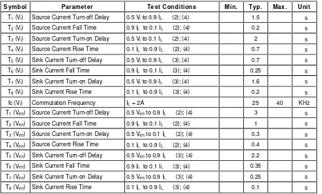
ELECTRICAL CHARACTERISTICS(continued)
Symbol Parameter Test Conditions Min. Typ. Max. Unit
T1(Vi) Source Current Turn-off Delay 0.5 Vito 0.9 IL (2); (4) 1.5 s
T2(Vi) Source Current Fall Time 0.9 IL to 0.1 IL (2); (4) 0.2 s
T3(Vi) Source Current Turn-on Delay 0.5 Vito 0.1 IL (2); (4) 2 s
T4(Vi) Source Current Rise Time 0.1 IL to 0.9 IL (2); (4) 0.7 s
T5(Vi) Sink Current Turn-off Delay 0.5 Vito 0.9 IL (3); (4) 0.7 s
T6(Vi) Sink Current Fall Time 0.9 IL to 0.1 IL (3); (4) 0.25 s
T7(Vi) Sink Current Turn-on Delay 0.5 Vito 0.9 IL (3); (4) 1.6 s
T8(Vi) Sink Current Rise Time 0.1 IL to 0.9 IL (3); (4) 0.2 s
fc (Vi) Commutation Frequency IL= 2A 25 40 KHz
T1(Ven) Source Current Turn-off Delay 0.5 Vento 0.9 IL (2); (4) 3 s
T2(Ven) Source Current Fall Time 0.9 IL to 0.1 IL (2); (4) 1 s
T3(Ven) Source Current Turn-on Delay 0.5 Vento 0.1 IL (2); (4) 0.3 s
T4(Ven) Source Current Rise Time 0.1 IL to 0.9 IL (2); (4) 0.4 s
T5(Ven) Sink Current Turn-off Delay 0.5 Vento 0.9 IL (3); (4) 2.2 s
T6(Ven) Sink Current Fall Time 0.9 IL to 0.1 IL (3); (4) 0.35 s
T7(Ven) Sink Current Turn-on Delay 0.5 Vento 0.9 IL (3); (4) 0.25 s
T8(Ven) Sink Current Rise Time 0.1 IL to 0.9 IL (3); (4) 0.1 s
1) 1)Sensing voltage can be –1 V for t 50 sec; in steady state Vsensmin – 0.5 V.
2) See fig. 2. 3) See fig. 4.
4) The load must be a pure resistor.
Figure 1 :Typical Saturation Voltage vs. Output Current.
Figure 2 :Switching Times Test Circuits.
L298
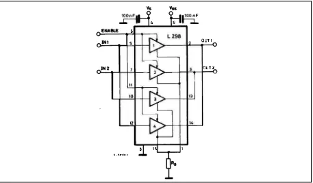
Figure 7 :For higher currents, outputs can be paralleled. Take care to parallel channel 1 with channel 4 and channel 2 with channel 3.
APPLICATION INFORMATION (Refer to the block diagram)
1.1. POWER OUTPUT STAGE
The L298 integrates two power output stages (A ; B). The power output stage is a bridge configuration and its outputs can drive an inductive load in com-mon or differenzial mode, depending on the state of the inputs. The current that flows through the load comes out from the bridge at the sense output : an external resistor (RSA; RSB.) allows to detect the
in-tensity of this current. 1.2. INPUT STAGE
Each bridge is driven by means of four gates the in-put of which are In1 ; In2 ; EnA and In3 ; In4 ; EnB. The In inputs set the bridge state when The En input is high ; a low state of the En input inhibits the bridge. All the inputs are TTL compatible.
2. SUGGESTIONS
A non inductive capacitor, usually of 100 nF, must be foreseen between both Vs and Vss, to ground, as near as possible to GND pin. When the large ca-pacitor of the power supply is too far from the IC, a second smaller one must be foreseen near the L298.
The sense resistor, not of a wire wound type, must be grounded near the negative pole of Vs that must be near the GND pin of the I.C.
Each input must be connected to the source of the driving signals by means of a very short path. Turn-On and Turn-Off : Before to Turn-ON the Sup-ply Voltage and before to Turn it OFF, the Enable in-put must be driven to the Low state.
3. APPLICATIONS
Fig 6 shows a bidirectional DC motor control Sche-matic Diagram for which only one bridge is needed. The external bridge of diodes D1 to D4 is made by four fast recovery elements (trr 200 nsec) that must be chosen of a VF as low as possible at the worst case of the load current.
The sense output voltage can be used to control the current amplitude by chopping the inputs, or to pro-vide overcurrent protection by switching low the en-able input.
The brake function (Fast motor stop) requires that the Absolute Maximum Rating of 2 Amps must never be overcome.
When the repetitive peak current needed from the load is higher than 2 Amps, a paralleled configura-tion can be chosen (See Fig.7).
An external bridge of diodes are required when in-ductive loads are driven and when the inputs of the IC are chopped ; Shottky diodes would be preferred.
T
1
PING)))™ Ultraso
The Parallax PI NG))) ultrasonic dis from about 2 cm (0.8 inches) to 3 Javelin Stamp microcontrollers, requ
The PI NG))) sensor works by trans providing an output pulse that cor sensor. By measuring the echo puls
Features
• Supply Voltage – 5 VDC • Supply Current – 30 mA typ; • Range – 2 cm to 3 m (0.8 in • I nput Trigger – positive TTL • Echo Pulse – positive TTL pu • Echo Hold-off – 750 µs from • Burst Frequency – 40 kHz fo • Burst I ndicator LED shows s • Delay before next measurem • Size – 22 mm H x 46 mm W
Dimensions
E3
10
599 Menlo Drive, Suite 100 Rocklin, California 95765, USA
Office:(916) 624-8333
Fax:(916) 624-8003
General:[email protected]
Technical:support@parall
Web Site:www.parallax.co
Educational:www.stamps
sonic Distance Sensor (#28
distance sensor provides precise, non-contact distan 3 meters (3.3 yards). I t is very easy to connect to quiring only one I / O pin.
ansmitting an ultrasonic (well above human hearing corresponds to the time required for the burst echo
ulse width the distance to target can easily be calculate
yp; 35 mA max in to 3.3 yrds)
TL pulse, 2 uS min, 5 µs typ. pulse, 115 uS to 18.5 ms om fall of Trigger pulse
for 200 µs s sensor activity
Pin Definitions
GND Ground (Vss) 5 V 5 VDC (Vdd) SIG Signal (I/O pin)
The PI NG))) sensor has a male 3-pi (5 VDC), ground, and signal. The plugged into a solderless breadboa through the use of a standard serv # 805-00002). Standard connection the right.
Quick-Start Circuit
This circuit allows you to quickly c Education® breadboard area. The Vdd, and the SI G pin connects to
Ping_Demo.BS2listed on page 7.
Servo Cable and Port Cautio
I f you want to connect your PI NG))) using a servo extension cable, follow
1. When plugging the cable on Black to GND, Red to 5 V, an 2. Check to see if your Board
jumper, as shown at right. 3. I f your Board of Education s
to Vdd as shown.
4. I f your Board of Educatio jumper, do not use them w ports only provide Vin, not PI NG))) sensor. Go to the ne 5. Connect the servo cable dir
3-pin header. Then, use jum Vss, Red to Vdd, and White
-pin header used to supply power e header allows the sensor to be oard, or to be located remotely rvo extender cable (Parallax part tions are show in the diagram to
connect your PI NG))) sensor to a BASI C Stamp® 2 e PI NG))) module’ s GND pin connects to Vss, the 5
to I / O pin P15. This circuit will work with the 7.
tions
))) sensor to a Board of Education low these steps:
onto the PI NG))) sensor, connect , and White to SI G.
rd of Education servo ports have a .
n servo ports have a jumper, set it
tion servo ports do not have a with the PI NG))) sensor. These t Vdd, and this may damage your next step.
directly to the breadboard with a jumper wires to connect Black to te to I / O pin P15.
B 7
Board of Educat Jumper,
2 via the Board of 5 V pin connects to e example program
Theory of Operation
The PI NG))) sensor detects objects by emitting a short ultrasonic burst and then "listening" for the echo. Under control of a host microcontroller (trigger pulse), the sensor emits a short 40 kHz (ultrasonic) burst. This burst travels through the air at about 1130 feet per second, hits an object and then bounces back to the sensor. The PI NG))) sensor provides an output pulse to the host that will terminate when the echo is detected, hence the width of this pulse corresponds to the distance to the target.
Test Data
A1301 and A1302
Continuous-Time Ratiometric Linear Hall Effect Sensor ICs
Features and Benefits
▪ Low-noise output
▪ Fast power-on time
▪ Ratiometric rail-to-rail output
▪ 4.5 to 6.0 V operation
▪ Solid-state reliability
▪ Factory-programmed at end-of-line for optimum performance
▪ Robust ESD performance
Packages: 3-pin SOT23W (suffix LH), and 3-pin SIP (suffix UA)
Not to scale
Description
The A1301 and A1302 are continuous-time, ratiometric, linear Hall-effect sensor ICs. They are optimized to accurately provide a voltage output that is proportional to an applied magnetic field. These devices have a quiescent output voltage that is 50% of the supply voltage. Two output sensitivity options are provided: 2.5 mV/G typical for the A1301, and 1.3 mV/G typical for the A1302.
The Hall-effect integrated circuit included in each device includes a Hall circuit, a linear amplifier, and a CMOS Class A output structure. Integrating the Hall circuit and the amplifier on a single chip minimizes many of the problems normally associated with low voltage level analog signals.
High precision in output levels is obtained by internal gain and offset trim adjustments made at end-of-line during the manufacturing process.
These features make the A1301 and A1302 ideal for use in position sensing systems, for both linear target motion and rotational target motion. They are well-suited for industrial applications over extended temperature ranges, from–40°C to 125°C.
Two device package types are available: LH, a 3-pin SOT23W type for surface mount, and UA, a 3-pin ultramini SIP for through-hole mount. They are lead (Pb) free (suffix,–T) with
100% matte tin plated leadframes.
Selection Guide
Part Number Packing* Package Ambient, TA Sensitivity (Typical)
A1301EUA-T Bulk, 500 pieces/bag SIP –40ºC to 85ºC
2.5 mV/G A1301KLHLT-T 7-in. tape and reel, 3000 pieces/reel Surface Mount
–40ºC to 125ºC
A1301KUA-T Bulk, 500 pieces/bag SIP
A1302ELHLT-T 7-in. tape and reel, 3000 pieces/reel Surface Mount –40ºC to 85ºC
1.3 mV/G A1302KLHLT-T 7-in. tape and reel, 3000 pieces/reel Surface Mount
–40ºC to 125ºC
A1302KUA-T Bulk, 500 pieces/bag SIP
*Contact Allegro™ for additional packing options.
Absolute Maximum Ratings
Characteristic Symbol Notes Rating Units
Supply Voltage VCC 8 V
Output Voltage VOUT 8 V
Reverse Supply Voltage VRCC –0.1 V
Reverse Output Voltage VROUT –0.1 V
Output Sink Current IOUT 10 mA
Operating Ambient Temperature TA
Range E –40 to 85 ºC
Range K –40 to 125 ºC
Maximum Junction Temperature TJ(max) 165 ºC
Symbol Number Description Package LH Package UA
VCC 1 1 Connects power supply to chip
VOUT 2 3 Output from circuit
GND 3 2 Ground
Pin-out Drawings
Package LH Package UA
3
1 2 1 2 3
Terminal List
DEVICE CHARACTERISTICSover operating temperature range, TA, and VCC= 5 V, unless otherwise noted
Characteristic Symbol Test Conditions Min. Typ. Max. Units
Electrical Characteristics
Supply Voltage VCC Running, TJ< 165°C 4.5 – 6 V
Supply Current ICC Output open – – 11 mA
Output Voltage VOUT(High) ISOURCE= –1 mA, Sens = nominal 4.65 4.7 – V
VOUT(Low) ISINK= 1 mA, Sens = nominal – 0.2 0.25 V
Output Bandwidth BW – 20 – kHz
Power-On Time tPO
VCC(min)to 0.95 VOUT;B = ±1400 G;
Slew rate = 4.5 V/μ s to 4.5 V/100 ns – 3 5 μ s
Output Resistance ROUT ISINK≤ 1 mA, ISOURCE ≥ –1 mA – 2 5 Ω
Wide Band Output Noise, rms VOUTN
External output low pass filter ≤ 10 kHz;
Sens = nominal – 150 – μ V
Ratiometry
Quiescent Output Voltage Error with respect to ∆V 1
CC
Δ VOUTQ(V) TA= 25°C – – ±3.0 %
Magnetic Sensitivity Error with respect to ∆V 2
Quiescent Output Voltage over
Operating Temperature Range VOUTQ(TA) B = 0 G 2.2 – 2.8 V
Magnetic Sensitivity Sens A1301; TA= 25°C 2.0 2.5 3.0 mV/G
A1302; TA= 25°C 1.0 1.3 1.6 mV/G
Magnetic Sensitivity over
Operating Temperature Range Sens(TA)
A1301 1.8 – 3.2 mV/G
A1302 0.85 – 1.75 mV/G
LAMPIRAN C
GAMBAR REALISASI ROBOT MOBIL
Realisasi Robot Mobil...C-1 Realisasi Pengujian Mencari Parkir dan mengatur posisi parkir pada jarak 70cm...C-2 Realisasi Pengujian Mencari parkir dan mengatur
BAGIAN KIRI ROBOT MOBIL
BAGIAN DEPAN DAN BELAKANG ROBOT MOBIL
C-1
Realisasi Pengujian Mencari parkir dan mengatur posisi parkir pada jarak 70 cm
1
Universitas Kristen Maranatha
BAB I PENDAHULUAN
Pada bab ini akan dibahas mengenai latar belakang, identifikasi masalah, perumusan masalah, tujuan, pembatasan masalah, metodologi, dan sistematika penulisan.
1.1 Latar Belakang
Akhir-akhir ini telah dikembangkan teknologi berupa kendaraan yang dapat mengendalikan dirinya secara otomatis yang lebih dikenal dengan Unmanned
Aerial Vehicle (UAV). Definisi UAV adalah wahana yang dapat mengendalikan dirinya secara otomatis tanpa interferensi dari luar. Contoh aplikasinya dalam bidang militer misalnya untuk keperluan pengintaian musuh, daerah berbahaya, perbatasan, pengamatan dan penelitian keadaan atmosfer, hutan, laut, dan lain-lain.
Salah satu kelebihan dari UAV diantaranya adalah kemampuan kendaraan untuk mengatur posisi secara otomatis. Contohnya kendaraan dapat mengatur posisi parkir secara otomatis. Dalam Tugas Akhir yang berjudul “Perancangan dan Realisasi Auto Parking Pada Robot Mobil Menggunakan modul Mikrokontroler Arduino Uno”diharapkan dapat mendukung kelebihan dari UAV tersebut.
Dalam Tugas Akhir ini, dibuat sebuah robot mobil yang dapat mencari lahan parkir kosong dan mengatur posisi parkir secara otomatis. Lahan parkir yang digunakan adalah lahan parkir paralel datar yang berada disebelah kiri. Lahan parkir kosong dideteksi dengan menggunakan sensor ultrasonik. Setelah lahan parkir kosong ditemukan, ukuran lahan pakir kosong (space) diukur menggunakan
sensor rotary encoder(hall effect). Kedua sensor ini dikendalikan oleh sebuah
2
robot mobil. Sedangkan, motor DC bagian belakang berfungsi sebagai penggerak roda belakang robot mobil.
1.2 Identifikasi Masalah
Berdasarkan latar belakang diatas, masalah utama yang diangkat pada tugas akhir ini adalah merancang sebuah robot mobil yang dapat mendeteksi lahan parkir dan melakukan parkir secara otomatis.
1.3 Perumusan Masalah
Berdasarkan uraian yang telah dijelaskan diatas maka rumusan masalah adalah sebagai berikut:
• Bagaimana robot mobil dapat mencari lahan secara otomatis yang cukup untuk digunakan parkir paralel?
• Bagaimana robot mobil dapat melakukan parkir paralel dengan otomatis?
1.4 Maksud dan Tujuan
Tujuan yang ingin dicapai yaitu:
• Membuat robot mobil yang dapat mencari lahan parkir paralel secara otomatis.
• Membuat robot mobil yang dapat mengatur posisi parkir paralel secara otomatis.
1.5 Batasan Masalah
Untuk mencapai sasaran dan tujuan yang diinginkan ,maka permasalahan akan dibatasi sebagai berikut:
• Membuat robot mobil yang dapat mendeteksi lahan parkir paralel datar disebelah kiri dengan space minimum 2 kali ukuran panjang robot mobil dan mengatur posisi parkir dengan batasan dinding pembatas.
• Memanfaatkan modul Mikrokontroler Arduino Uno sebagai pengontrol utama
3
Universitas Kristen Maranatha
1. Pendeteksi lahan parkir paralel disebelah kiri robot mobil. 2. Mengatur posisi parkir dari robot mobil
• Menggunakan sensor rotary encoder (hall effect) sebagai penghitung jarak tempuh robot mobil.
• Start awal robot mobil dilakukan pada saat diam. 1.6 Sistematika Penulisan
• BAB I : PENDAHULUAN
Pada bab ini akan dibahas mengenai latar belakang, perumusan masalah, identifikasi masalah, tujuan, pembatasan masalah, metodologi dan sistematika penulisan.
• BAB II : LANDASAN TEORI
Bab ini akan membahas teori-teori yang akan digunakan untuk merancang dan merealisasikan “Perancangandan Realisasi Auto Parking Pada Robot Mobil Menggunakan modul Mikrokontroler Arduino Uno” yang meliputi pembahasan Mikrokontroler Arduino Uno, Sensor Jarak, Sensor hall
effect, Motor Driver, Motor DC.
• BAB III :PERANCANGAN DAN REALISASI
Pembahasan bab ini meliputi perancangan dan realisasi auto parking pada robot mobil menggunakan modul Mikrokontroler Arduino Uno. Perancangan meliputi masukan-proses-keluaran yang dikendalikan oleh modul Mikrokontroler Arduino Uno.
• BAB IV :DATA PENGAMATAN DAN ANALISIS
Pada bab ini,dilakukan pengujian pada robot mobil. Pengujian ini terdiri dari pengujian sensor jarak, pengujian sensor rotary encoder, pengujian untuk mencari lahan parkir dan pengujian untuk mengatur posisi parkir.
• BAB V : KESIMPULAN DAN SARAN
Bab ini merupakan bab penutup yang berisi kesimpulan dari hasil penelitian dan analisis dari Tugas Akhir ini serta saran bagi pihak yang terkait berkenaan dengan pembuatan “Perancangan dan Realisasi Auto Parking Pada Robot Mobil Menggunakan modul Mikrokontroler Arduino
46 BAB V
KESIMPULAN DAN SARAN
Bab ini merupakan bab penutup yang berisi kesimpulan dari hasil penelitian dan analisis dari Tugas Akhir ini serta saran bagi pihak yang terkait berkenaan dengan pembuatan “Perancangan Auto Parking Pada Robot Mobil Menggunakan Mikrokontroler Arduino Uno dan Sensor Jarak”
5.1 Kesimpulan
1. Perancangan dan realisasi Auto Parking pada Tugas Akhir ini berhasil mencari lahan parkir dan melakukan parkir secara otomatis sesuai dengan yang diharapkan.
2. Robot mobil dapat mencari lahan parkir kosong (di mulai pada kondisi diam) pada space 2 kali ukuran panjang robot mobil dengan jarak start awal maksimal 50 cm sebelum lahan kosong.
3. Keberhasilan robot mobil dapat melakukan parkir secara otomatis adalah sebesar 70% (berhasil sebanyak 21 kali dari 30 kali percobaan untuk space yang berbeda), hasil ini dinilai masih kurang memuaskan.
4. Kegagalan pengukuran jarak tempuh robot mobil yang disebabkan oleh sensor
Hall Effect mungkin diakibatkan adanya induksi magnet yang ditimbulkan
motor DC terhadap sensor Hall Effect.
5.2 Saran
1. Agar posisi roda kemudi robot mobil dalam kondisi lurus, disarankan ditambahkan sensor untuk mendeteksi kelurusan dari roda kemudi robot mobil.
2. Agar dapat mengatasi kegagalan pengukuran jarak tempuh robot mobil yang disebabkan oleh sensor Hall Effect, disarankan untuk menggunakan sensor
rotary encoder. Hal ini bertujuan agar sensor pembaca jumlah putaran tidak
47
48
DAFTAR PUSTAKA
1. Andrianto, H., Buku Panduan : Pelatihan Mikrokontroler AVR ATmega16, 2008.
2. A1301 and A1302 continuous-Time Ratiometric Linear Hall Effect Sensor Ics.Allegro
3. Budiharto, W., Membuat Robot Cerdas, Jakarta : Gramedia, 2006. 4. L 298 DUAL FULL-BRIDGE DRIVER.STMicroelectronics 5. PING)))Ultrasonic Distance Sensor(#28015).Parralax
6. 8-bit AVR Microcontroller with 4/8/16/32K Bytes In-Systm Programmable Flash.Atmel
7. http://en.wikipedia.org/wiki/pulse-width-modulation(diakses 12 Januari 2013) 8. http://id.wikipedia.org/wiki/parkir