Geoff Varrall
Roger Belcher
3G Handset and
Developmental Editor: Kathryn A. Malm Managing Editor: Micheline Frederick
Text Design & Composition: Wiley Composition Services
Designations used by companies to distinguish their products are often claimed as trademarks. In all instances where Wiley Publishing, Inc., is aware of a claim, the product names appear in initial capital or ALL CAPITAL LETTERS. Readers, however, should contact the appropriate compa-nies for more complete information regarding trademarks and registration.
This book is printed on acid-free paper. ∞
Copyright © 2003 by Geoff Varrall and Roger Belcher. All rights reserved. Published by Wiley Publishing, Inc., Indianapolis, Indiana
Published simultaneously in Canada
No part of this publication may be reproduced, stored in a retrieval system, or transmitted in any form or by any means, electronic, mechanical, photocopying, recording, scanning, or otherwise, except as permitted under Section 107 or 108 of the 1976 United States Copyright Act, without either the prior written permission of the Publisher, or authorization through payment of the appropriate per-copy fee to the Copyright Clearance Center, Inc., 222 Rose-wood Drive, Danvers, MA 01923, (978) 750-8400, fax (978) 750-4470. Requests to the Pub-lisher for permission should be addressed to the Legal Department, Wiley Publishing, Inc., 10475 Crosspoint Blvd., Indianapolis, IN 46256, (317) 572-3447, fax (317) 572-4447, E-mail: [email protected].
Limit of Liability/Disclaimer of Warranty: While the publisher and author have used their best efforts in preparing this book, they make no representations or warranties with respect to the accuracy or completeness of the contents of this book and specifically disclaim any implied warranties of merchantability or fitness for a particular purpose. No warranty may be created or extended by sales representatives or written sales materials. The advice and strategies contained herein may not be suitable for your situation. You should consult with a professional where appropriate. Neither the publisher nor author shall be liable for any loss of profit or any other commercial damages, including but not limited to special, inci-dental, consequential, or other damages.
For general information on our other products and services please contact our Customer Care Department within the United States at (800) 762-2974, outside the United States at (317) 572-3993 or fax (317) 572-4002.
Wiley also publishes its books in a variety of electronic formats. Some content that appears in print may not be available in electronic books.
ISBN: 0-471-22936-9
for his gift of curiosity; to my mother Winifred for her gift of confidence;
and to my wife Deborah for her gift of our marriage.
Acknowledgments xix
Introduction xxi
Part One
3G Hardware
1
Chapter 1 Spectral Allocations—Impact on Handset Hardware Design 3
Setting the Stage 3
Duplex Spacing for Cellular (Wide Area) Networks 7 Multiplexing Standards: Impact on Handset Design 11
FDMA 11
TDMA 11
CDMA 13
Difference between CDMA and TDMA 14
Modulation: Impact on Handset Design 15
Future Modulation Schemes 17
TDMA Evolution 19
5 MHz CDMA: IMT2000DS 21
Advantages of 5 MHz RF Channel Spacing 24
Impact of Increasing Processor Power on Bandwidth Quality 24 Multiplexing 24
Source Coding 25
Channel Coding 27
Convolution and Correlation 29
Summary 30
A Note about Radio Channel Quality 31
A Note about Radio Bandwidth Quality 32
Contents
Chapter 2 GPRS/EDGE Handset Hardware 33
Design Issues for a Multislot Phone 33
Design Issues for a Multiband Phone 37
Design Issues for a Multimode Phone 39
The Design Brief for a Multislot, Multiband, Multimode Phone 39 Receiver Architectures for Multiband/Multimode 40
Direct Conversion Receivers 43
To Sum Up 47
Transmitter Architectures: Present Options 47
Issues to Resolve 48
GPRS RF PA 51
Manage Power-Level Difference Slot to Slot 52
Power Amplifier Summary 54
Multiband Frequency Generation 54
Summary 56
Chapter 3 3G Handset Hardware 57
Getting Started 57
Code Properties 59
Code Properties—Orthogonality and Distance 60 Code Capacity—Impact of the Code Tree and
Non-Orthogonality 63
Common Channels 64
Synchronization 64
Dedicated Channels 66
Code Generation 68
Root Raised Cosine Filtering 70
Modulation and Upconversion 72
Power Control 74
The Receiver 74
The Digital Receiver 74
The RAKE Receive Process 77
Correlation 79
Receiver Link Budget Analysis 80
IMT2000DS Carrier-to-Noise Ratio 83
Receiver Front-End Processing 85
Received Signal Strength 87
IMT2000TC 88 GPS 89
Bluetooth/IEEE802 Integration 90
Infrared 91 Radio Bandwidth Quality/Frequency Domain Issues 91 Radio Bandwidth Quality/Time Domain Issues 94
IMT2000 Channel Coding 95
Reed-Solomon, Viterbi, and Turbo Codes in IMT2000 95
Future Modulation Options 95
Characterizing Delay Spread 96
Conformance/Performance Tests 98 Impact of Technology Maturation on Handset and
Network Performance 100
3GPP2 Evolution 100
CDMA2000 Downlink and Uplink Comparison 103
Implementation Options 103
Linearity and Modulation Quality 103
Frequency Tolerance 104
Frequency Power Profile 105
Summary 109 Chapter 4 3G Handset Hardware Form Factor and Functionality 111 Impact of Application Hardware on Uplink Offered Traffic 111
Voice Encoding/Decoding (The Vocoder) 111
CMOS Imaging 114
The Keyboard 116
Rich Media 116
The Smart Card SIM 117
The MPEG-4 Encoder 120
Other Standards 120
Battery Bandwidth as a Constraint on Uplink Offered Traffic 122 Impact of Hardware Items on Downlink Offered Traffic 122 Speaker 122
Display Driver and Display 123
How User Quality Expectations Increase Over Time 127
Alternative Display Technologies 128
MPEG-4 Decoders 131
Handset Power Budget 133
Processor Cost and Processor Efficiency 134
Future Battery Technologies 135
Handset Hardware Evolution 136
Adaptive Radio Bandwidth 138
Who Will Own Handset Hardware Value? 139
Summary 140
Chapter 5 Handset Hardware Evolution 141
A Review of Reconfigurability 141
Flexible Bandwidth Needs Flexible Hardware 146 Summary 146
Part Two
3G Handset Software
149
Chapter 6 3G Handset Software Form Factor and Functionality 151 An Overview of Application Layer Software 151
Higher-Level Abstraction 154
The Cost of Transparency 154
Exploring Memory Access Alternatives 156 Software/Hardware Commonality with
Game Console Platforms 159
Add-On/Plug-On Software Functionality 161
Add-in/Plug-in Software Functionality:
Smart Card SIMS/USIMS 161
The Distribution and Management of Memory 162 Summary 165
Chapter 7 Source Coding 167
An Overview of the Coding Process 167
Voice 167 Text 168 Image 169 Video 170
Applying MPEG Standards 172
Object-Based Variable-Rate Encoders/Decoders 175
Virtual Reality Modeling Language 175
Automated Image Search Engines 177
Digital Watermarking 177
The SMS to EMS to MMS Transition 178
Quality Metrics 179
Summary 182
Chapter 8 MExE-Based QoS 185
An Overview of Software Component Value 185
Defining Some Terms 186
Operating System Performance Metrics 187
The OSI Layer Model 187
MExE Quality of Service Standards 190
Maintaining Content Value 191
Network Factors 192
Summary 194
Chapter 9 Authentication and Encryption 197
The Interrelated Nature of Authentication and Encryption 197
The Virtual Private Network 198
Key Management 198
Digital Signatures 199
Hash Functions and Message Digests 200
Public Key Infrastructure 200
Security Management 201
Virtual Smart Cards and Smart Card Readers 204
Where to Implement Security 204
The IPSec Standard 204
Encryption Theory and Methods 207
Encryption and Compression 207
Evolving Encryption Techniques 208
DES to AES 208
Smart Card SIMS 208
Biometric Authentication 209
Working Examples 210
Over-the-Air Encryption 210
Public Key Algorithms: The Two-Key System 210
Prime Numbers 211
Congruency 212
Diffie-Hellman Exchange 214
Vulnerability to Attack 214
Authentication: Shared Secret Key 216
Digital Signatures 218
Secret Key Signatures 218
Public Key Cryptography 219
Summary 220
Chapter 10 Handset Software Evolution 221
Java-Based Solutions 221
Developing Microcontroller Architectures 223
Hardware Innovations 224
Add-in Modules 224
Looking to the Future 225
Authentication and Encryption 225
Agent Technology 226
Summary 227
Part Three 3G Network Hardware
229
Chapter 11 Spectral Allocations—Impact on Network Hardware Design 231 Searching for Quality Metrics in an Asynchronous Universe 231
Typical 3G Network Architecture 232
The Impact of the Radio Layer on Network
Bandwidth Provisioning 234
The Circuit Switch is Dead—Long Live the Circuit Switch 235
BTS and Node B Form Factors 236
Typical 2G Base Station Product Specifications 236
3G Node B Design Objectives 241
2G Base Stations as a Form Factor and
Power Budget Benchmark 241
Node B Antenna Configuration 242
The Benefits of Sectorization and Downtilt Antennas 244 Node B RF Form Factor and RF Performance 245
Node B Receiver Transmitter Implementation 246
The 3G Receiver 247
The Digitally Sampled IF Superhet 247
The Direct Conversion Receiver (DCR) 247
The 3G Transmitter 249
The RF/IF Section 249
The Baseband Section 255
Technology Trends 256
System Planning 257
The Performance/Bandwidth Trade Off in
1G and 2G Cellular Networks 258
TDMA/CDMA System Planning Comparisons 261
Radio Planning 263
Rules of Thumb in Planning 266
How System Performance Can Be Compromised 267 Timing Issues on the Radio Air Interface 268
Use of Measurement Reports 269
Uplink Budget Analysis 272
Long-Term Objectives in System Planning:
Delivering Consistency 273
Wireless LAN Planning 274
Cellular/Wireless LAN Integration 278
Distributed Antennas for In-Building Coverage 278 Summary 279
Chapter 12 GSM-MAP/ANSI 41 Integration 281
Approaching a Unified Standard 281
Mobile Network Architectures 283
GSM-MAP Evolution 289
GPRS Support Nodes 290
The SGSN Location Register 290
The GGSN GPRS Gateway Support Node 290
Session Management, Mobility Management, and Routing 292
Location Management 293
Micro and Macro Mobility Management 293
Radio Resource Allocation 294
Operation and Maintenance Center 295
Summary 295
Chapter 13 Network Hardware Optimization 297
A Primer on Antennas 297
Dipole Antennas 299
Directional Antennas 299
Omnidirectional Antennas 301
Dish Antennas 303
Installation Considerations 303
Smart Antennas 303
The Flexibility Benefit 304
Switched Beam Antennas versus Adaptive Antennas 305
Conventional versus Smart Antennas 305
Distributed Antennas 309
A Note about Link Budgets and Power 309
Positioning and Location 310
Smart Antennas and Positioning 313
Superconductor Devices 313
Filter Basics 314
The Q factor 314
The Cavity Resonator 317
The Cavity Resonator in Multicoupling Applications 317
Circulators and Isolators 317
Example 1 318
Example 2 318
Hybrid Directional Couplers 318
Multichannel Combining 321
Superconductor Filters and LNAs 322
RF over Fiber: Optical Transport 322
Optical Transport in the Core Network 324
Optical Selectivity 327
Optical Transport Performance 328
Wavelength Division and Dense Wavelength-Division
Multiplexing 328 Summary 330 Antennas 330
Superconductor Devices 330
Optical Components 331
Chapter 14 Offered Traffic 333
Characterizing Traffic Flow 333
The Preservation of Traffic Value (Content Value) 334
The Challenge for IP Protocols 334
Radio and Network Bandwidth Transition 334
Traffic Distribution 335
Protocol Performance 336
Admission Control versus Policy Control 337
Offered Traffic at an Industry Level 338
Converging Standards 338
The Five Components of Traffic 338
The Four Classes of Traffic 339
Sources of Delay, Error, and Jitter Sensitivity 339 Solutions to Delay and Delay Variability 341
Managing the Latency Budget 341
Delivering Quality of Service 342
Traditional Call Management in a Wireless Network 343
Session Management in a 3G Network 344
The Challenges of Wireline and Wireless Delivery 346
The Cost of Quality 347
Meeting the Costs of Delivery 347
The Persistency Metric 349
Overprovisioning Delivery Bandwidth 350
Session Switching 351
Preserving and Extracting Traffic Value 351 The Cost of Asymmetry and Asynchronicity 353 Considering the Complexity of Exchange 353
Archiving Captured Content 354
Increasing Offered Traffic Loading 355
Predicting Offered Traffic Load 356
Summary 357
Chapter 15 Network Hardware Evolution 359
The Hierarchical Cell Structure 359
Local Area Connectivity 360
Wireless LAN Standards 360
Delivering a Consistent User Experience 362
Sharing the Spectrum with Bluetooth 363
Working in a Real Office Environment 364
Joining the Scatternet Club 364
The Bluetooth Price Point 365
Dealing with Infrared 365
Plug-in Modules 365
A Network within a Network within a Network 366
Low-Power Radio and Telemetry Products 367
Broadband Fixed-Access Network Hardware Evolution 368
Weather Attenuation Peaks 369
Mesh Networks 372
Fixed-Access Wireless Access Systems 372
Alternative Fixed-Access and Mobility Access
Wireless Delivery Platforms 374
The NIMBY Factor 375
Setting the Stage for Satellite 375
Satellite Networks 375
Early Efforts 375
Present and Future Options 376
Iridium 377 Globalstar 378 ORBCOMM 378 Inmarsat 378
Calculating the Costs 378
Satellites for Fixed Access 379
Part Four
3G Network Software
383
Chapter 16 The Traffic Mix Shift 385
The Job of Software 385
Critical Performance Metrics 386
Radio Bandwidth Quality 386
The Performance of Protocols 387
Network Resource Allocation 387
Service Parameters 388
Power Control and Handover 388
The Evolution of Network Signaling 389
Second-Generation Signaling 389
Third-Generation Signaling 390
Protocol Stack Arrangement 391
Load Distribution 392
3G Frame Structure 393
2G Versus 3G Session Management 393
Communications between Networks 397
Why We Need Signaling 398
Moving Beyond the Switch 399
Letting the Handset Make the Decisions 399 Dealing with SS7 and Existing Switching Architectures 400
Making a Choice 400
Summary 401
Chapter 17 Traffic Shaping Protocols 403
An Overview of Circuit Switching 403
Moving Toward a Continuous Duty Cycle 404
Deterministic Response to Asynchronous Traffic 404
Dealing with Delay 405
Deep Packet Examination 406
Address Modification and Queuing 407
Packet Loss and Latency Peaks 408
Buffering Bandwidth 411
Multiple Routing Options 412
IP Switching 412
The Transition from IPv4 to IPv6 413
Delivering Router Performance in a Network 414
Improving Router Efficiency 416
Traffic Shaping Protocols: Function
and Performance 416
Resource Pre-Reservation Protocol 416
Multiprotocol Label Switching 417
Diffserv 418
Session Initiation Protocol 418
Measuring Protocol Performance 419 Levels of Reliability and Service Precedence 420
Classes of Traffic in GPRS and UMTS 421
Switching and Routing Alternatives 421
ATM: A Case Study 422
Available Bit Rate Protocol 423
The Four Options of ATM 424
Efficient Network Loading 424
ATM, TCP/IP Comparison 425
The IP QoS Network 427
The Future of ATM: An All-IP Replacement 427
IP Wireless: A Summary 428
The IPv4-to-IPv6 Transition 428
IP Traffic Management 428
IP-Based Network Management 429
IP-Based Mobility Management 429
IP-Based Access Management 429
Mobile Ad Hoc Networks 431
The Internet Protocol Alternative 432
Zone and Interzone Routing 432
Route Discovery and Route Maintenance Protocols 434 IP Terminology Used in Ad Hoc Network Design 434
Administering Ad Hoc User Groups 436
A Sample Application 436
Achieving Protocol Stability 436
Macro Mobility in Public Access Networks 437
Mobile IP 437
Macro Mobility Management 438
Use of IP in Network Management 438
The Impact of Distributed Hardware and
Distributed Software in a 3G Network 440
IP over Everything 441
A Note about Jumbograms: How Large Is that
Packet in Your Pocket? 441
Software-Defined Networks 442
The Argument for Firmware 443
3G Network Considerations 444
Summary 444
Chapter 18 Service Level Agreements 445
Managing the Variables 445
Defining and Monitoring Performance 446
Determining Internet Service Latency 446
Addressing Packet Loss Issues 446
Network Latency and Application Latency 447
Billing and Proof-of-Performance Reporting 448
Real-Time or Historical Analysis 448
Measuring Performance Metrics 448
GPRS Billing 450
Session-Based Billing 451
Toward Simplified Service Level Agreements 452
Qualifying Quality 452
Bandwidth Quality versus Bandwidth Cost 452
Personal and Corporate SLA Convergence 453
Specialist SLAs 453
Range and Coverage 453
Onto Channel Time 454
User Group Configurations 454
Content Capture Applications 454
Specialist Handsets 454
Site-Specific Software Issues 455
Mandatory Interoperability 455
Hardware Physical Test Requirements 455
Specialized Network Solutions 456
The Evolution of Planning in Specialist Mobile Networks 457 Summary 458 Chapter 19 3G Cellular/3G TV Software Integration 461
The Evolution of TV Technology 461
The Evolution of Web-Based Media 462
Resolving Multiple Standards 464
Working in an Interactive Medium 465
Delivering Quality of Service on the Uplink 465
The ATVEF Web TV Standard 466
Integrating SMIL and RTP 466
The Implications for Cellular Network Service 467
Device-Aware Content 468
The Future of Digital Audio and Video Broadcasting 468
Planning the Network 470
The Difference Between Web TV, IPTV, and Digital TV 473
Co-operative Networks 474
Summary 475
Chapter 20 Network Software Evolution 477
A Look at Converging Industries and Services 477
Managing Storage 478
Managing Content 478
Using Client/Server Agent Software 479
Delivering Server and Application Transparency 480
Storage Area Networks 480
Application Persistency 481
Interoperability and Compatibility 482
Network Software Security 484
Model-Driven Architectures 485
Testing Network Performance 485
The Challenge of Software Testing 486
Test Languages 487
Measuring and Managing Consistency 488
Why Is Consistency Important? 488
3G Consistency Metrics 488
Summary 489
The Phases of Cellular Technologies 490
Preserving Bursty Bandwidth Quality 493
Appendix Resources 495
This book is the product of over 15 years of working with RTT, delivering strategic technology design programs for the cellular design community. This has included pro-grams on AMPS/ETACS handset, base station, and network design in the early to mid-1980s; programs on GSM handset, base station, and network design from the late 1980s to mid-1990s onward; and, more recently, programs on 3G handset, Node B, and network design.
We would like to thank the many thousands of delegates who have attended these programs in Europe, the United States, and Asia and who have pointed out the many misconceptions that invariably creep in to the study of a complex subject.
We would also like to thank our other colleagues in RTT: Dr. Andrew Bateman for keeping us in line on matters of DSP performance and design issues; Miss Tay Siew Luan of Strategic Advancement, Singapore, for providing us with an Asian technology perspective; our valued colleagues from the Shosteck Group, Dr. Herschel Shosteck, Jane Zweig, and Rich Luhr, for providing us with valuable insights on U.S. technology and market positioning; our colleague, Adrian Sheen, for keeping our marketing alive while we were knee-deep in the book; and last but not least, Lorraine Gannon for her heroic work on the typescript.
Also thanks to our families for putting up with several months of undeserved distraction.
Any errors which still reside in the script are entirely our own, so as with all techni-cal books, approach with circumspection.
We hope you enjoy the complexity of the subject, challenge our assumptions, find our mistakes (do tell us about them by emailing [email protected] or roger@rtt online.com), and get to the end of the book intrigued by the potential of technology to unlock commercial advantage.
Geoff Varrall and Roger Belcher
Acknowledgments
This book is written for hardware and software engineers presently involved or want-ing to be involved in 3G handset or 3G network design. Over the next 20 chapters, we study handset hardware, handset software, network hardware, and network software.
A Brief Overview of the Technology
Each successive generation of cellular technology has been based on a new enabling technology. By new, we often mean the availability of an existing technology at low cost, or, for handset designers, the availability of a technology sufficiently power-efficient to be used in a portable device. For example:
First generation (1G). AMPS/ETACS handsets in the 1980s required low-cost microcontrollers to manage the allocation of multiple RF (radio frequency) channels (833 ×30 kHz channels for AMPS, 1000 ×25 kHz channels for ETACS) and low-cost RF components that could provide acceptable performance at 800/900 MHz.
Second generation (2G). GSM, TDMA, and CDMA handsets in the 1990s required low-cost digital signal processors (DSPs) for voice codecs and related baseband processing tasks, and low-cost RF components that could provide acceptable performance at 800/900 MHz, 1800 MHz, and 1900 MHz.
Third generation (3G). W-CDMA and CDMA2000 handsets require—in addition to low-cost microcontrollers and DSPs—low-cost, low power budget CMOS or CCD image sensors; low-cost, low power budget image and video encoders; low-cost, low power budget memory; low-cost RF components that can provide acceptable performance at 1900/2100 MHz; and high-density battery technologies.
Introduction
Bandwidth Quantity and Quality
Over the next few chapters we analyze bandwidth quantity and quality. We show how application bandwidth quality has to be preserved as we move complex content (rich media) into and through a complex network. We identify how bandwidth quality can be measured, managed, and used as the foundation for quality-based billing method-ologies. We show how the dynamic range available to us at the application layer will change over the next 3 to 5 years and how this will influence radio bandwidth and net-work topology.
We define bandwidth quality in terms of application bandwidth, processor band-width, memory bandband-width, radio bandband-width, and network bandband-width, and then we identify what we need to do to deliver consistently good end-to-end performance.
Hardware Components
Hardware components are divided into physical hardware and application hardware, as follows:
Physical hardware. The hardware needed to support the radio physical layer— putting 0s and 1s on to a radio carrier, and getting 0s and 1s off a radio carrier
Application hardware. The hardware needed to capture subscriber content (microphones, vocoders, imaging, and video encoders) and to display content (speakers, displays, and display drivers)
A typical 3G handset includes a microphone (audio capture); CMOS imager and MPEG-4 encoder (for image and video encoding); a keyboard (application capture); a smart card for establishing access and policy rights; and, on the receive side, a speaker, display driver, and display. The addition of these hardware components (CMOS imager, MPEG-4 encoder, and high-definition color display) changes what a user can do and what a user expects from the device and from the network to which the device is connected.
Software Components
Software footprint and software functionality is a product of memory bandwidth (code and application storage space), processor bandwidth (the speed at which instructions can be processed), and code bandwidth (number of lines of code). Over the past three generations of cellular phone, memory bandwidth has increased from a few kilobytes to a few Megabytes to a few Gigabytes. Processor bandwidth has increased from 10 MIPS (millions of instructions per second) to 100 MIPS to 1000 MIPS, and code band-width has increased from 10,000 to 100,000 to 1,000,000 lines of code (using the Star-Core SC140 as a recent example).
The composition of the code in a 3G handset determines how a 3G network is used. Software form factor and functionality determine application form factor and functionality.
Physical layer software. Manages the Medium Access Control (MAC) layer—the allocation and access to radio and network bandwidth.
Application layer software. Manages the multiple inputs coming from the hand-set application hardware (microphone, vocoder, encoder) and the media multi-plex being delivered on the downlink (network to handset).
Rich Media Properties
It is generally assumed that an application may consist of a number of traffic streams simultaneously encoded onto multiple channel streams. These components are often referred to as rich media.
The properties of these rich media components need to be preserved as they move across the radio interface and into and through the core network. By propertieswe mean voice quality (audio fidelity), image and video quality, and data/application integrity. Properties represent value, and it is the job of a 3G handset and network designer to ensure an end-to-end Quality of Service that preserves this property value.
How This Book Is Organized
The deliberate aim of this book is to combine detail (the small picture) with an overview of how all the many parts of a 3G network fit, or should fit, together (the big picture). In meeting this aim, the content of this book is arranged in four parts of five chapters each, as follows:
Part I: 3G Hardware. We look at the practical nuts and bolts of cellular handset design, how band allocations and regulatory requirements determine RF perfor-mance, the processing needed to capture signals from the real world (analog voice and analog image and video), and the processing needed to translate these signals into the digital domain for modulation onto a radio carrier. We discuss the different requirements for RF processing and baseband processing: How we manage and manipulate complex content to deliver a consistent end-to-end user experience. In the following chapters we introduce the various concepts related to bandwidth quality: How we achieve consistent performance over the radio physical layer.
■■ Chapter 1 reviews some of the design challenges created by the spectral
allocation process.
■■ Chapter 2 shows that making products do something they were not
designed to do often leads to a disappointing outcome (as shown in a case study of GPRS/EDGE handset hardware).
■■ Chapter 3 highlights the hardware requirements of a 3G handset design—
■■ Chapter 4 analyzes how the additional hardware items in a handset—image
capture platform, MPEG-4 encoder, color display—influence network offered traffic.
■■ Chapter 5 reviews some issues of handset hardware configurability. Part II: 3G Handset Software. We explore how handset software is evolving and
the important part handset software plays in shaping offered traffic and build-ing traffic value.
■■ Chapter 6 case studies application software—what is possible now and
what will be possible in the future.
■■ Chapter 7 analyzes source coding techniques.
■■ Chapters 8 and 9 begin to explore how we build session value by providing
differentiated service quality and differentiated access rights.
■■ Chapter 10 complements Chapter 5 by looking at software configurability
and future handset software trends.
Part III: 3G Network Hardware. We launch into network hardware, returning to the nuts and bolts.
■■ Chapter 11 reviews some of the design challenges introduced by the
spec-tral allocation process, in particular, the design challenges implicit in deliv-ering efficient, effective base station/Node B hardware.
■■ Chapter 12 looks at some of the present and future network components—
what they do, what they don’t do, and what they’re supposed to do.
■■ Chapter 13 covers base station/Node B antennas and other link gain
prod-ucts, including high-performance filters, RF over fiber, and optical trans-port.
■■ Chapter 14 talks us through the dimensioning of bursty bandwidth—how
we determine the properties of offered traffic in a 3G network.
■■ Chapter 15 evaluates the particular requirements for broadband fixed
access and some of the hardware requirements for media delivery net-works.
Part IV: 3G Network Software. We address network software—the implications of managing audio, image, video, and application streaming; the denomination and delivery of differentiated Quality of Service; and related measurement and management issues.
■■ Chapter 16 analyzes end-user performance expectations, how expectations
increase over time, and the impact this has on network software.
■■ Chapter 17 reviews traffic shaping protocols and the performance issues
implicit in using Internet protocols to manage complex time-dependent traffic streams.
■■ Chapter 18 follows on, hopefully logically, with an explanation of the
■■ Chapter 19 explores some of the practical consequences of 3G cellular and
3G TV software integration.
■■ Chapter 20 reviews, as a grand finale, storage bandwidth and storage area
network technologies.
The Objective: To Be Objective
We could describe some parts of this book as “on piste,” others as “off piste.” The on piste parts describe what is—the present status of handset and network hardware and software. Other parts set out to describe what will be. From experience, we know that when authors speculate about the future, the result can be intensely irritating. We argue, however, that you do not need to speculate about the future. We can take an objective view of the future based on a detailed analysis of the present and the past, starting with an analysis of device level evolution.
Predicting Device Level Evolution
Device hardware is becoming more flexible—microcontrollers, DSPs, memory, and RF components are all becoming more adaptable, capable of undertaking a wide range of tasks. As device hardware becomes more flexible, it also becomes more complex. Adding smart antennas to a base station is an example of the evolution of hardware to become more flexible—and, in the process, more complex.
As handset hardware becomes more complex, it becomes more capable in terms of its ability to capture complex content. Our first chapters describe how handset hard-ware is evolving—for example, with the integration of digital CMOS imaging and MPEG-4 encoding. As handset hardware becomes more complex, the traffic mix shifts, becoming more complex as well. As the offered traffic mix (uplink traffic) becomes more complex, its burstiness increases. As bandwidth becomes burstier, network hard-ware has to become more complex. This is described in the third part of the book.
As handset and network hardware increases in complexity, software complexity increases. We have to control the output from the CMOS imager and MPEG-4 encoder, and we have to preserve the value of the captured content as the content is moved into and through our complex network. As hardware flexibility increases, software flexibil-ity has to increase.
Fortunately, device development is very easy to predict. We know by looking at process capability what will be possible (and economic) in 3 to 5 years’ time. We can very accurately guess what the future architecture of devices such as microcontrollers, DSPs, memory, and RF components will be in 3 to 5 years’ time. These devices are the fundamental building blocks of a 3G network.
Bridging the Reality Gap
Too often we fail to learn from lessons of the past. As an industry, we have over 20 years of experience in designing cellular handsets and deploying cellular networks. The past tells us precisely what is and what is not possible in terms of future technol-ogy deployment. This allows us to detect when reality gaps occur. Reality gaps are those between technical practicality and wishful thinking. They happen all the time and can be particularly painful when technically complex systems are being deployed. Almost all technologies start with a reality gap. The technology fails to deliver as well as expected. Some technologies never close the gap and become failed technolo-gies. Some people can make money from failed technologies, but the majority doesn’t. Failed technologies ultimately fail because they do not deliver user value.
We also tend to forget that user expectations and customer expectations change over time. A technology has to be capable of sufficient dynamic range to be able to continue to improve as the technology and user expectations mature. Failed technologies often fail because they cannot close the reality gap and cannot catch up with changing user expectations.
Successful technologies are technologies that deliver along the whole industry value chain—device vendors, handset manufacturers, network manufacturers (software and hardware vendors), network operators, and end users.
We aim to show how 3G technology is evolving to become a successful proposition, both technically and commercially. We hope you enjoy and profit from the next 20 chapters.
Before We Start: A Note about Terms
In this book we use the term handsetto describe a generic, nonspecific portable cellular terminal. When we use the term mobile, we are referring to a portable terminal of higher power and capable of traveling at high speed. It is usually vehicle-mounted and may have antenna gain.
One
3 In this first chapter we explain the characteristics of the radio spectrum, how over the past 100 years enabling component technologies have provided us with access to pro-gressively higher frequencies, and how this in turn has increased the amount of RF (radio frequency) bandwidth available. We show how enabling component technolo-gies initially provided us with the ability to deliver increasingly narrow RF channel spacing in parallel with the introduction of digital encoding and digital modulation techniques. We explain the shift, from the 1980s onward, toward wider RF channel spacing through the use of TDMA (Time Division Multiple Access) and CDMA (Code Division Multiple Access) multiplexing techniques and identify benefits in terms of component cost reduction and performance gain, in particular the impact of translat-ing tasks such as selectivity, sensitivity, and stability from RF to baseband.
Setting the Stage
By baseband, we mean the original information rate. For analog voice, baseband would be used to refer to the 3 kHz of audio bandwidth. This would then be preprocessed. Pre-emphasis/de-emphasis would be used to tailor the high-frequency response and reduce high-frequency noise. Companding(compression/expansion) would be used to compress the dynamic range of the signal. The signal would then be modulated onto an RF carrier using amplitude or frequency modulation. Usually, an intermediate step between base-band and RF would be used, known as the IF processing stage(intermediate frequency). We still use IF processing today and will discuss its merits/demerits in a later section.
Spectral Allocations—Impact on
Handset Hardware Design
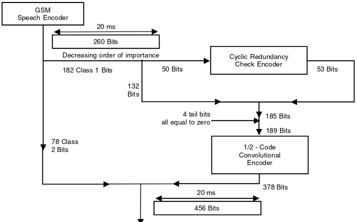
In a 2G handset, baseband refers to the information rate of the encoder (for example, 13 kbps) and related digital signaling bandwidth. The data is then channel coded—that is, additional bits are added to provide error protection—and then the data is modu-lated onto an RF carrier, usually with an IF processing stage. In a 3G handset, baseband refers to the information rate of the vocoder, parallel image and video encoder rates, other data inputs, and related channel coding.
First-generation handsets therefore have a baseband running at a few kilohertz, and second-generation handsets a few tens of kilohertz.
Third-generation handsets have a user data rate that can vary between a few kilo-hertz and, in the longer term, several megakilo-hertz. The user data is channel coded and then spread using a variable spreading code to a constant baseband rate known as the chip rate—for example, 1.2288 Mcps (million chips per second; a clock rate of 1.2288 MHz) or 3.84 Mcps (a clock rate of 3.84 MHz). This baseband data, after spreading, has to be modulated onto an RF carrier (producing a 1.25 or 5 MHz bandwidth), sometimes via an IF. The RF will be running at 1900/2100 MHz.
Essentially, the higher the frequency, the more expensive it is to process a signal. The more we can do at baseband, the lower the cost. This is not to downplay the impor-tance of the RF link. The way in which we use the RF bandwidth and RF power avail-able to us has a direct impact on end-to-end quality of service.
Ever since the early experiments of Hughes and Hertz in the 1880s, we have searched for progressively more efficient means of moving information through free space using electromagnetic propagation. By efficiencywe mean the ability to send and receive a relatively large amount of information across a relatively small amount of radio bandwidth using a relatively small amount of RF power generated by a relatively power-efficient amplifier in a relatively short period of time.
The spark transmitters used to send the first long-distance (trans-Atlantic) radio transmissions in the early 1900s were effective but not efficient either in terms of their use of bandwidth or the efficiency with which the RF power was produced and applied. What was needed was an enabling technology.
Thermionic and triode valves introduced in the early 1900s made possible the appli-cation of tuned circuits, the basis for channelized frequencies giving long-distance (and relatively) low-power communication. Tuned circuits reduced the amount of RF power needed in a transceiver and provided the technology needed for portable Morse code transceivers in World War I.
Efficiency in RF communication requires three performance parameters:
Sensitivity. The ability to process a low-level signal in the presence of noise and/or distortion
Selectivity. The ability to recover wanted signals in the presence of unwanted signals
Stability. The ability to stay within defined parameters (for example, frequency and power) under all operating conditions when transmitting and receiving
noise, and to deliver receive selectivity, due to filter performance. On the other hand, as we move to higher frequencies, we have access to more bandwidth..
For example, we have only 370 kHz of bandwidth available at long wave; we have 270 GHz available in the millimetric band (30 to 300 GHz). Also, as frequency increases, range decreases. (Propagation loss increases with frequency). This is good news and bad news. A good VHF transceiver—for example, at 150 MHz—can transmit to a base station 40 or 50 kilometers away, but this means that very little frequency reuse is available. In a 900 MHz cellular network, frequencies can be used within (rel-atively) close proximity. In a millimetric network, at 60 GHz, attenuation is 15 dB per kilometer—a very high level of frequency reuse is available.
Another benefit of moving to higher frequencies is that external or received noise (space or galactic noise) reduces above 100 MHz. As you move to 1 GHz and above, external noise more or less disappears as an influence on performance (in a noise rather than interference limited environment) and receiver design—particularly LNA design—becomes the dominant performance constraint.
An additional reason to move to higher frequencies is that smaller, more compact resonant components—for example, antennas, filters, and resonators—can be used. Remember, RF wavelength is a product of the speed of light (300,000,000 meters per second) divided by frequency, as shown in Table 1.1.
During the 1920s, there was a rapid growth in broadcast transmission using long wave and medium wave. The formation of the BBC in 1922 was early recognition of the political and social importance of radio broadcasting. At the same time, radio amateurs such as Gerald Marcuse were developing equipment for long-distance shortwave com-munication. In 1932, George V addressed the British Empire on the shortwave world service. In practice, there has always been substantial commonality in the processing techniques used for radio and TV broadcasting and two-way and later cellular radio— a convergence that continues today.
Table 1.1 Frequency and Wavelength Relationship
SPEED OF LIGHT IN METERS PER
FREQUENCY SECOND DIVIDED BY FREQUENCY WAVELENGTH
100 MHz 300,000,000 = 3 m
100,000,000
300 MHz 300,000,000 = 1 m
300,000,000
900 MHz 300,000,000 = 0.33 m
900,000,000
2 GHz 300,000,000 = 0.15 m
In 1939, Major Edwin Armstrong introduced FM (frequency modulation) into radio broadcasting in the United States. FM had the advantage over AM (amplitude modu-lation) of the capture effect. Provided sufficient signal strength was available at the receiver, the signal would experience gain through the demodulator, delivering a sig-nificant improvement in signal-to-noise ratio. The deeper the modulation depth (that is, the more bandwidth used), the higher the gain. Additionally, the capture effect made FM more resilient to (predominantly AM) interference. Toward the end of World War II, the U.S. Army introduced FM radios working in the VHF band. The combina-tion of the modulacombina-tion and the frequency (VHF rather than shortwave) made the FM VHF radios less vulnerable to jamming.
Fifty years later, CDMA used wider bandwidth channels to deliver bandwidth gain (rather like wideband FM processor/demodulator gain). Rather like FM, CDMA was, and is, used in military applications because it is harder to intercept.
A shortwave or VHF portable transceiver in 1945 weighed 40 kg. Over the next 50 years, this weight would reduce to the point where today a 100 gm phone is considered overweight.
Parallel developments included a rapid increase in selectivity and stability with a reduction in practical channel spacing from 200 kHz in 1945 to narrowband 12.5, 6.25, or 5 kHz transceivers in the late 1990s, and reductions in power budget, particularly after the introduction of printed circuit boards and transistors in the 1950s and 1960s. The power budget of an early VHF transceiver was over 100 Watts. A typical cell phone today has a power budget of a few hundred milliWatts.
As active and passive device performance has improved and as circuit geometries have decreased, we have been able to access higher parts of the radio spectrum. In doing so, we can provide access to an ever-increasing amount of radio bandwidth at a price affordable to an ever-increasing number of users.
As RF component performance improved, RF selectivity also improved. This resulted in the reduction of RF channel spacing from several hundred kHz to the narrowband channels used today—12.5 kHz, 6.25 kHz, or 5 kHz (used in two-way radio products).
In cellular radio, the achievement of sensitivity and selectivity is increasingly dependent on baseband performance, the objective being to reduce RF component costs, achieve better power efficiency, and deliver an increase in dynamic range. The trend since 1980 has been to relax RF channel spacing from 25 kHz (1G) to 200 kHz (2G GSM; Global System for Mobile Communication) to 5 MHz (3G). In other words, to go wideband rather than narrowband.
Handset design objectives remain essentially the same as they have always been— sensitivity, selectivity, and stability across a wide dynamic range of operational condi-tions, though the ways in which we achieve these parameters may change. Likewise, we need to find ways of delivering year-on-year decreases in cost, progressive weight and size reduction, and steady improvements in product functionality.
Historically, there has also been a division between wide area accessusing duplex spaced bands (sometimes referred to as paired bands) in which the transmit frequen-cies are separated by several MHz or tens of MHz from receive frequenfrequen-cies, and local area access using nonpaired bands in which the same frequency is used for transmit and receive. Some two-way radios, for example, still use single frequency working with a press-to-talk (PTT) key that puts the transceiver into receive or transmit mode. Digital cordless phones use time-division duplexing. One time slot is used for trans-mit, the next for receive, but both share the same RF carrier.
One reason why cellular phones use RF duplexing and cordless phones do not is because a cellular phone transmits at a higher power. A cordless phone might transmit at 10 mW, a cellular handset transmits at between 100 mW and 1 Watt, a cellular base station might transmit at 5, 10, 20, or 40 Watts. For these higher-power devices, it is par-ticularly important to keep transmit power out of the receiver.
Duplex Spacing for Cellular (Wide Area) Networks
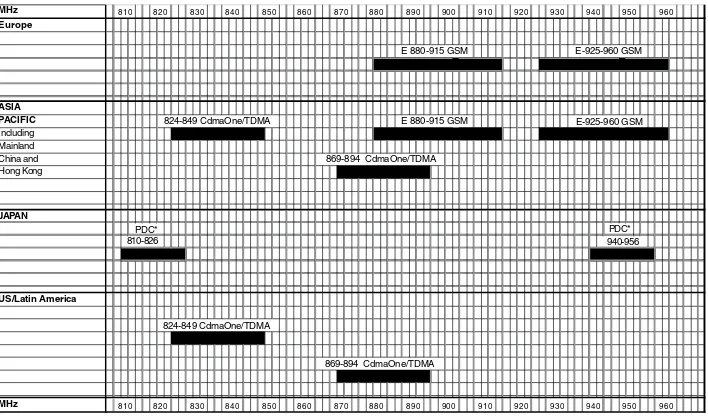
Given that receive signal powers are often less than a picoWatt, it is clear that RF duplex spaced bands tend to deliver better receive sensitivity and therefore tend to be used for wide area coverage systems. Wide area two-way radio networks in the UHF band typically use 8 MHz or 10 MHz duplex spacing, 800/900 MHz cellular networks use 45 MHz duplex spacing, GSM 1800 uses 95 MHz duplex spacing, PCS 1900 uses 80 MHz, and IMT2000 (3G) uses 190 MHz duplex spacing. In the United States, there are also proposals to refarm 30 MHz of TV channel bandwidth in the 700 MHz band for 3G mobile services.
Figure 1.1 shows the duplex spacing implemented at 800/900 MHz for GSM in Europe, CDMA/TDMA in the United States, and PDC (Japan’s 2G Personal Digital Cel-lular standard) in Japan. PDC was implemented with 130 MHz duplex spacing (and 25 kHz channel spacing), thus managing to be different than all other 2G cellular standards.
Figure 1.1 Cellular frequency allocations—800/900 MHz with duplex spacing.
MHz 810 820 830 840 850 860 870 880 890 900 910 920 930 940 950 960 Europe
E 880-915 GSM E-925-960 GSM
ASIA
PACIFIC 824-849 CdmaOne/TDMA E 880-915 GSM E-925-960 GSM
Including Mainland
China and 869-894 CdmaOne/TDMA
Hong Kong
In Asia, countries with existing Advanced Mobile Phone System (AMPS), and CDMA/TDMA allocations have a problem in that the upper band of AMPS overlaps the lower band of GSM. As the GSM band is paired, this means the corresponding bands in the upper band of GSM are unusable. The result is that certain countries (Hong Kong being the most obvious example) had a shortage of capacity because of how the spectrum had been allocated. Latin America has the same 800/900 MHz allo-cation as the United States (also shown in Figure 1.1). In the United States and Latin America, however, the AMPS 2 ×25 MHz allocations are bounded by politically
sensi-tive public safety specialist mobile radio spectrum, preventing any expansion of the US 800 MHz cellular channel bandwidth.
In Europe, the original (1G) TACS allocation was 2 ×25 MHz from 890 to 915 MHz
and 935 to 960 MHz (1000 ×25 kHz channels), which was later extended (E-TACS) to
33 MHz (1321 ×25 kHz channels). GSM was deployed in parallel through the early to
mid-1990s and now includes 25 MHz (original allocation), plus 10 MHz (E-GSM), plus 4 MHz for use by European railway operators (GSM-R), for a total of 39 MHz or 195 ×
200 kHz RF channels
Additional spectrum was allocated for GSM in the early 1990s at 1800 MHz (GSM1800). This gave three bands of 25 MHz each to three operators (75 MHz—that is, 375 ×200 kHz paired channels). As with all duplex spaced bands, handset transmit is
the lower band. (Because of the slightly lower free space loss, this is better for a power-limited handset.) Only a fraction of this bandwidth is actually used, rather undercut-ting operator’s claims to be suffering from a shortage of spectrum.
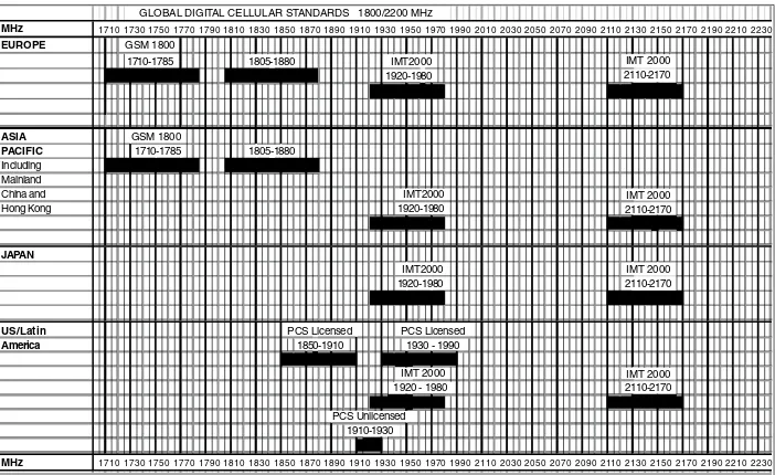
Figure 1.2 Cellular frequency allocations at 1800, 1900, and 2100 MHz.
GLOBAL DIGITAL CELLULAR STANDARDS 1800/2200 MHz
MHz 1710 1730 1750 1770 1790 1810 1830 1850 1870 1890 1910 1930 1950 1970 1990 2010 2030 2050 2070 2090 2110 2130 2150 2170 2190 2210 2230
EUROPE GSM 1800
1710-1785 1805-1880 IMT2000 IMT 2000
1920-1980 2110-2170
ASIA GSM 1800
PACIFIC 1710-1785 1805-1880 Including
Mainland
China and IMT2000 IMT 2000
Hong Kong 1920-1980 2110-2170
JAPAN
IMT2000 IMT 2000
1920-1980 2110-2170
US/Latin PCS Licensed PCS Licensed
America 1850-1910 1930 - 1990
IMT 2000 IMT 2000
1920 - 1980 2110-2170
PCS Unlicensed 1910-1930
In the United States and Latin America, 2 ×60 MHz was allocated at 1850 to 1910
and 1930 to 1990 MHz for US TDMA (30 kHz) or CDMA (1.25 MHz) channels or GSM (200 kHz) channels (GSM 1900), as shown in Figure 1.2. Unfortunately, the upper band of PCS 1900 overlaps directly with the lower band of IMT2000, the official ITU alloca-tion for 3G. The intenalloca-tion for the IMT allocaalloca-tion was to make 2 ×60 MHz available,
divided into 12 ×5 MHz channels, and this has been the basis for European and Asian
allocations to date. In addition, 3 ×5 MHz nonpaired channels were allocated at 2010
to 2025 MHz and 4 ×5 MHz nonpaired channels at 1900 to 1920 MHz. The air interface
for the paired bands is known as IMT2000DS, and for the nonpaired bands, it is IMT2000TC. (We discuss air interfaces later in this chapter.)
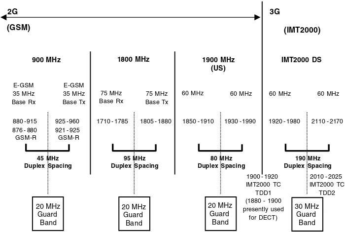
Figure 1.3 shows the RF bandwidth that needs to be addressed if the brief is to pro-duce an IMT2000 handset that will also work in existing 2G networks (GSM 900, GSM 1800, GSM 1900) co-sharing with US TDMA and CDMA.
Some countries have the 60 MHz IMT2000 allocation divided among five operators. Five licensees sharing a total of 60 MHz would each have 12 MHz of spectrum. As this is not compatible with 5 MHz channel spacing, two operators end up with 3 ×5 MHz
paired bands and three operators end up with 2 ×5 MHz paired bands and a
non-paired band (either in TDD1 or TDD2). It will therefore be necessary in some cases to support IMT2000DS and IMT2000TC in a dual-mode handset. The handset configura-tion would then be IMT2000DS, IMT2000TC, GSM 1900, GSM 1800, and GSM 900. Table 1.2 shows that selectivity and sensitivity are increasingly achieved at baseband, reducing the requirement for RF filters and relaxing the need for frequency stability. The need for backward compatibility, however, makes this benefit harder to realize.
Figure 1.3 Tri-band GSM and IMT2000 allocations. 900 MHz 1800 MHz 1900 MHz
Table 1.2 Simplified RF Architecture
SPECTRUM CHANNEL NO. OF RF
SPACING CHANNELS
1G E-TACS 33 MHz 25 kHz 1321
AMPS 25 MHz 30 kHz 833
2G GSM 900 39 MHz 200 kHz 195
GSM 1800 75 MHz 200 kHz 375 GSM 1900 60 MHz 200 kHz 300
3G IMT2000DS 60 MHz 5 MHz 12
IMT2000TC 35 MHz 5 MHz 7
First-generation AMPS/ETACS phones were required to access a large number of 25 kHz RF channels. This made synthesizer design (the component used to lock the handset onto a particular transmit and receive frequency pair) quite complex. Also, given the relatively narrowband channel, frequency stability was critical. A 1 ppm (part per million) temperature compensated crystal oscillator was needed in the hand-set. It also made network planning (working out frequency reuse) quite complex.
In second generation, although relaxing the channel spacing to 200 kHz reduced the number of RF channels, the need for faster channel/slot switching made synthesizer design more difficult. However, adopting 200 kHz channel spacing together with the extra complexity of a frequency and synchronization burst (F burst and S burst) allowed the frequency reference to relax to 2.5 ppm—a reduction in component cost.
In third generation, relaxing the channel spacing to 5 MHz reduces the number of RF channels, relaxes RF filtering, makes synthesizer design easier, and helps relax the frequency reference in the handset (to 3 ppm). Unfortunately, you only realize these cost benefits if you produce a single-mode IMT2000 phone, and, at present, the only country likely to do this—for their local market—is Japan.
Additionally you might choose to integrate a Bluetooth or IEEE 802 wireless LAN into the phone or a GPS (Global Positioning System/satellite receiver). In the longer term, there may also be a need to support a duplex (two-way) mobile satellite link at 1980 to 2010 and 2170 to 2200 MHz. In practice, as we will see in the following chap-ters, it is not too hard to integrate different air interfaces at baseband. The problem tends to be the RF component overheads.
Multiplexing Standards: Impact on Handset Design
We have just described how RF channel allocation influences RF performance and handset design. Multiplexing standards are similarly influenced by the way RF chan-nels are allocated. In turn, multiplexing standards influence handset design.
There are three options, or a combination of one or more of these:
■■ Frequency Division Multiple Access (FDMA)
■■ Time Division Multiple Access (TDMA)
■■ Code Division Multiple Access (CDMA)
FDMA
A number of two-way radio networks still just use FDMA to divide users within a given frequency band onto individual narrowband RF channels. Examples are the European ETSI 300/230 digital PMR (Private Mobile Radio) standard in which users have access to an individual digitally modulated 12.5 kHz or 6.25 kHz channel, the French TETRAPOL standard in which users have access to an individual digitally modulated 12.5, 10, or 6.25 kHz channel, and the US APCO 25 standard in which users have access to an individual digitally modulated 12.5 kHz or 6.25 kHz RF channel.
Narrowband RF channels increase the need for RF filtering and an accurate fre-quency reference (typically better than 1 ppm long-term stability). They do, however, allow for a narrowband IF implementation that helps minimize the noise floor of the receiver. The result is that narrowband two-way radios work well and have good sen-sitivity and good range in noise-limited environments, including VHF applications where atmospheric noise makes a significant contribution to the noise floor. The only disadvantage, apart from additional RF component costs, is that maximum data rates are constrained by the RF channel bandwidth, typically to 9.6 kbps.
TDMA
The idea of TDMA is to take wider band channels, for example, 25 kHz, 30 kHz, or 200 kHz RF channels and time-multiplex a number of users simultaneously onto the channel. Time slots are organized within a frame structure (frames, multiframes, superframes, hyperframes) to allow multiple users to be multiplexed together in an organized way. The objective is to improve channel utilization but at the same time relax the RF performance requirements (filtering and frequency stability) and reduce RF component costs in the handset and base station.
An example of TDMA used in two-way radio is the European Trans European Trunked Radio Access (TETRA) standard. A 25 kHz channel is split into four time slots each of 14.17 ms, so that up to 4 users can be modulated simultaneously onto the same 25 kHz RF carrier.
Figure 1.4 GSM slot structure.
In the United States, the AMPS 30 kHz analog channels were subdivided during the 1990s using either TDMA or CDMA. The time-division multiplex uses a three-slot structure (three users per 30 kHz RF channel), which can optionally be implemented as a six-slot structure.
A similar time-division multiplex was implemented in the Japanese Personal Digi-tal Cellular networks but using a 25 kHz rather than 30 kHz RF channel spacing. In Europe, an eight-slot time multiplex was implemented for GSM using a 200 kHz RF channel, as shown in Figure 1.4.
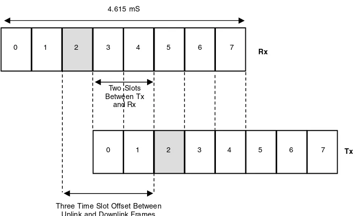
One specific objective of the air interface was to reduce RF component cost by relax-ing the RF channel spacrelax-ing, from 25 kHz to 200 kHz. In common with all other TDMA interfaces, additional duplex separation is achieved by introducing a time offset. In GSM, transmit and receive are both on the same time slot—for example, time slot 2 but with a three-slot frame offset. This helps to keep transmit power (+30 dBm) out of the receiver front end (having to detect signals at –102 dBm or below). The combination of RF and time-division duplexing helps to deliver good sensitivity and provides the option to reduce RF component costs by dispensing with the duplex filter in some GSM phone designs.
Another route to reducing component costs is to use the air interface to provide syn-chronization and frequency correction as part of the handset registration procedure— an S burst to synchronize, an F burst to provide a frequency fix.
A long, simple burst on the forward control channel aligns the handset, in time, to the downlink time slots. In the frequency domain, the modulation is given a unidirec-tional π/2 phase shift for similar successive bits, giving a demodulated output of a sine
wave at 1625/24 kHz higher than the center carrier frequency. This means that the F burst aligns the handset, in frequency, to the downlink RF carrier.
4.615 ms frame
0 1 2 3 4 5 6 7
0 1 2 3 4 5 6 7
CDMA
In the mid-1990s CDMA cellular networks began to be deployed in the United States, Korea, and parts of Southeast Asia. Effectively, CDMA takes many of the traditional RF tasks (the achievement of selectivity, sensitivity, and stability) and moves them to base-band. The objective is to deliver processing gain that can in turn deliver coverage and/capacity advantage over the coverage and/capacity achievable from a TDMA air interface. Endless arguments ensued between the TDMA and CDMA camps as to which technology was better.
In practice, because of political and regulatory reasons and other factors such as tim-ing, vendor, and operator support, GSM became the dominant technology in terms of numbers of subscribers and numbers of base stations deployed, which in turn con-ferred a cost and market advantage to GSM vendors. However, the technology used in these early CDMA networks has translated forward into 3G handset and network hardware and software. It is easier to qualify some of the design options in 3G hand-sets if we first cover the related design and performance issues highlighted by CDMA implementation to date.
The original principle of CDMA, which still holds true today, is to take a relatively narrowband modulated signal and spread it to a much wider transmitted bandwidth. The spreading occurs by multiplying the source data with a noise like high-rate pseudorandom code sequence—the pseudorandom number (PN). The PN as a digital number appears to be random but is actually predictable and reproducible having been obtained from a prestored random number generator. The product of the source data and the PN sequence becomes the modulating signal for the RF carrier.
At the receive end, the signal is multiplied by the same prestored PN sequence that was used to spread the signal, thereby recovering the original baseband (source) digi-tal data. Only the signal with the same PN sequence despreads. Effectively, the PN sequences characterize the digital filter, which correlates or captures wanted signal energy, leaving unwanted signal energy down in the noise floor.
Multiple users can exist simultaneously on the same RF channel by ensuring that their individual spreading codes are sufficiently different to be unique. To control access and efficiency on a CDMA network, the spreading code is a composite of several digital codes, each performing a separate task in the link. It is usual to refer to each sequence or code as a channel.
IS95 defines the dual-mode AMPS/CDMA technology platform, IS96 the speech coding (currently either 8 kbps or 13 kbps), IS97 and 98 the performance criteria for base stations and handsets, and IS99 data service implementation. What follows is therefore a description of the IS95 air interface, which then served as the basis for CDMA2000.
Walsh codes are a sequence of PN codes that are orthogonal in that, provided they remain synchronized with each other, the codes do not correlate or create co-code or adjacent code interference. Orthogonal codes are codes of equal distance (the number of symbols by which they differ is the same). The cross correlation—that is, code inter-ference—is zero for a perfectly synchronous transmission.
On the uplink, the channel bits are grouped into 6-bit symbols. The 6-bit group (higher-order symbol) generates a 64-chip Walsh code. The orthogonality of the 64 codes gives an increased degree of uniqueness of data on the uplink—that is, it pro-vides selectivity.
The resultant Walsh code is combined with a long code. The composite channel rate is 1.228 Mcps; in other words, the code stream is running at a rate of 1.228 MHz. The long code is a PN sequence truncated to the frame length (20 ms). On the uplink, the long code provides user-to-user selectivity; on the downlink, one long code is used for all base stations but each base station has a unique PN offset (a total of 512 time PN off-sets are available). So within a relatively wideband RF channel, individual user chan-nels are identified on the downlink using Walsh codes—with long codes providing cell-to-cell selectivity—individual user channels are identified on the uplink by use of the 6-bit symbols, and long codes are used to provide user-to-user selectivity.
From a handset design point of view, digital filters have replaced the time slots and RF filters used in the TDMA networks. Although RF filtering is still needed to separate multiple 1.25 MHz RF carriers, it is intrinsically a simpler RF channel plan, and it can be implemented as a single-frequency network if traffic loading is relatively light and evenly distributed between cells.
Difference between CDMA and TDMA
An important difference between TDMA and CDMA is that in TDMA, the duty cycle of the RF amplifier is a product of the number of time slots used. A GSM handset using one time slot has a duty cycle of 1/8. Maximum output power of a 900 MHz GSM phone is 2 Watts. Effectively, the average maximum power available across an eight-slot frame is therefore 250 mW.
In CDMA, the handset is continuously transmitting but at a maximum of 250 mW. The total power outputs are therefore similar. In a TDMA phone, the RF burst has to be contained within a power/time template to avoid interference with adjacent time slots. The RF output power of the TDMA handset is adjusted to respond to changes in channel condition (near/far and fading effects) typically every 500 ms. In an IS95 CDMA phone, power control is done every 1.25 ms, or 800 times a second. This is done to ensure that user codes can be decorrelated under conditions of relatively stable received signal strength (energy per bit over the noise floor). Failure to maintain rea-sonably equivalent Eb/Nos (energy per bit over the noise floor) between code streams
will result in intercode interference.
Modulation: Impact on Handset Design
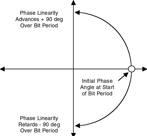
Information can be modulated onto an RF carrier by changing the amplitude of the car-rier, the frequency of the carcar-rier, or the phase of the carrier. For example, using Mini-mum Shift Keying (MSK), the carrier changes phase by +90° or -90° over a bit period (see Figure 1.5).
The example shown in Figure 1.5 is a constant envelope phase modulation scheme. Prior to modulation, the data stream passes through baseband filters. In Gaussian Min-imum Shift Keying (GMSK), these are Gaussian filters.
The advantage of GMSK, being constant envelope, is that it can be used with Class C amplifiers, which typically have a power efficiency of between 50 and 55 percent. The disadvantage is that with the GSM implementation of GMSK, because of the fil-tering, decision points on the modulation trellis are not always obtained, resulting in some residual bit errors. GMSK is a two-level modulation scheme—that is, the two phase states can represent a 0 or a 1.
Higher-level modulation states can be used to carry more bits per symbol. A four-state modulation scheme, for example, QPSK (Quadrature Phase Shift Keying) has 2 bits per symbol (00, 01, 11, 10), an eight-level modulation scheme can carry 3 bits per symbol, a 16-level modulation scheme can carry 4 bits per symbol, a 1024-level modu-lation scheme (used in fixed point-to-point, for example) can carry 10 bits per symbol. However, as the number of modulation states increase, the distance between phase states reduces and the likelihood of a demodulator error increases. Every time a modu-lation level is doubled (for example, from two-level to four-level), an additional 3 dB of signal energy is needed to maintain equivalent demodulator bit error rate performance.
Figure 1.5 Minimum shift keying (MSK). Initial Phase Angle at Start
of Bit Period
Phase Linearity Retards - 90 deg
Over Bit Period Phase Linearity Advances + 90 deg
Figure 1.6 IS54 TDMA—modulation vector—I Q diagram for π/4 DQPSK modulation.
Higher-level modulations also tend to contain amplitude components and can therefore not be used with power-efficient Class C amplification. The modulation tech-nique used in IS54 TDMA is an example (see Figure 1.6).
This is a four-level modulation technique known as π/4DQPSK. DQPSK refers to
“differential quadrature phase shift keying,” the use of four differentially encoded phase states to describe a 00, 01, 01, or 10. The π/4 indicates that the vector is indexed
by 45° at every symbol change. This makes it look like an eight-level modulation trel-lis, which it isn’t. It shows that any change from phase state to phase state avoids pass-ing through the center of the trellis, which would imply a 100 percent AM component. Instead the AM component is constrained to 70 percent.
Even so, the modulation requires a higher degree of linear amplification to avoid spectral regrowth during and after amplification. While this is reasonably easily accommodated in low-power handsets, it does result in larger—and hotter—RF ampli-fiers in IS54 TDMA base stations.
Similarly, CDMA uses QPSK on the downlink and offset QPSK on the uplink (as with π/4DQPSK, OQPSK reduces the AM components and relaxes the linearity
Future Modulation Schemes
The choice of modulation has always been a function of hardware implementation and required modulation and bandwidth efficiency. In the 1980s, FM provided—and still provides today—an elegant way of translating an analog waveform onto an (analog) RF carrier.
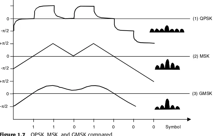
In the 1990s, GMSK was used for GSM as a relatively simple way to digitally mod-ulate or demodmod-ulate an RF carrier without the need for linearity in the RF PA. Note that GSM was developed as a standard in the early 1980s. US TDMA and IS95 CDMA were specified/standardized toward the end of the 1980s, by which time four-level modula-tion schemes (with AM components) were considered to provide a better efficiency trade-off. Figure 1.7 compares the performance trade-offs of QPSK (1), MSK (2), and GMSK (3). QPSK (1) carries 2 bits per symbol but has relatively abrupt phase changes at the symbol boundaries. MSK (2) has a constant rate of change of phase but still man-ages to maintain an open eye diagram at the symbol decision points. GMSK (3) has additional filtering (a Gaussian baseband filter that effectively slows the transition from symbol state to symbol state). The filtering ensures the modulation is constant envelope; the disadvantage is that decision points are not always achieved, resulting in a residual demodulated bit error rate.
QPSK is used in IMT2000MC and IMT2000DS on the downlink. HPSK is used on the uplink to reduce linearity requirements. A variant of IMT2000MC known as 1xEV, however, also has the option of using 8 PSK (also used in GSM EDGE implementation) and 16-level QAM. This seems to be a sensible way to increase bandwidth efficiency, given that eight-level modulation can carry 3 bits per symbol and 16 level can carry 4 bits per symbol.
Figure 1.7 QPSK, MSK, and GMSK compared.
(1) QPSK
(2) MSK
(3) GMSK
1 1 0 1 0 0 0 Symbol
0
0
0 -π/2
-π/2
-π/2
+π/2