ECCENTRICITY ON AN IMAGE CAUSED BY PROJECTION
OF A CIRCLE AND A SPHERE
R. Matsuoka a, *, S. Maruyama a
a Geospatial Technology Department, Kokusai Kogyo Co., Ltd., 2-24-1 Harumi-cho, Fuchu, Tokyo 183-0057, Japan - (ryuji_matsuoka, shintaro_maruyama)@kk-grp.jp
Commission V, WG V/1
KEY WORDS: Eccentricity, Projection, Circle, Sphere, Ellipse, Formula
ABSTRACT:
Circular targets on a plane are often utilized in photogrammetry, particularly in close range photogrammetry, while spherical targets are sometimes utilized in industrial applications. Both a circle and a sphere are projected as an ellipse onto an image. There is an eccentricity on an image between the centre of the projected ellipse and the projected location of the centre of a circle or a sphere. Since only the centre of the projected ellipse is measured, the correction of the eccentricity is considered to be necessary for highly accurate measurement. This paper shows a process to derive general formulae to calculate an eccentricity of a circle and a sphere using the size and the location of a circle or a sphere, and the focal length, the position and the attitude of a camera. Furthermore the paper shows methods to estimate the eccentricity of a circle and a sphere from the equation of the projected ellipse of a circle or a sphere on an image.
1. INTRODUCTION
There are many factors affecting the accuracy of image measurement. Some of them should be considered when we execute image measurement. We have conducted a camera calibration in order to correct radial and decentering lens distortions since the era of analytical photogrammetry using analogue films. In recent years the correction of colour aberrations becomes indispensable for highly accurate measurement (Kaufmann and Ladstädter, 2005, Luhmann et al., 2006a, Mallon and Whelan, 2007, Hattori et al., 2011). In the era of digital photogrammetry the fact that sampling and quantization in creating a digital image affect the accuracy of image measurement using digital images was reported (Matsuoka et al., 2011).
Furthermore there is an eccentricity of projection unless an object to be measured is a planar object lying on a plane parallel to the image plane of a camera. The eccentricity is a disparity on an image between the centre of the projected object and the projected location of the centre of an object. The correction of the eccentricity is considered to be necessary for highly accurate measurement.
In the meanwhile, circular targets on a plane are often utilized in photogrammetry, particularly in close range photogrammetry. Since a circle is radially symmetrical, circular targets are well suited for photogrammetric use such as camera calibration and 3D measurement. Although circular targets offer advantages of high image contrast, minimal size and high precision in image measurement, they have some drawbacks such as restricted visibility (typical: ±45°) depending on light source and reflective properties (Luhmann, 2014).
On the other hand, in industrial and other technical applications spherical targets are used in order to maximize visibility and enable tactile probing by other systems, for example coordinate measurement machines (CMM) (Luhmann, 2014). Spherical
targets are used in the German guideline VDI/VDE 2634 Part 2 for acceptance testing and re-verification of optical 3D measuring systems (Verein Deutscher Ingenieure, 2002).
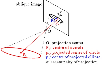
Both a circle on a plane and a sphere in space are projected as an ellipse onto an image. If a circle does not lie on a plane parallel to the image plane of a camera, or if the center of a sphere does not lie on the view vector of a camera, there is an eccentricity of projection to some extent. Figure 1 shows an eccentricity of projection of a circle.
O: projection center
P : centre of a circleC
p : projected centre of circleC
p : centre of projected ellipseE : eccentricity of projection e
oblique image
PC
pC
pE
O
eFigure 1. Eccentricity of projection of a circle
Regarding the eccentricity of a circle, Matsuoka et al. (2009) showed a formula calculating an eccentricity of a circle using the size and the location of a circle, and the focal length, the position and the attitude of a camera only when the circle lies on the horizontal plane. Moreover they presented merely the finally derived equation, although it would be convenient to show a process to derive the equation.
Luhmann (2014) reported the results of numerical simulations conducted in order to evaluate the effect of eccentricities to stereo and multi-image intersections. He quantified and investigated the eccentricities of circular targets and spherical
targets. Unfortunately he did not show a general formula calculating an eccentricity of a sphere.
This paper shows a process to derive general formulae to calculate an eccentricity of a circle and a sphere using the size and the location of a circle or a sphere, and the focal length, the position and the attitude of a camera. Furthermore the paper shows a method to estimate the eccentricity of a circle or a sphere from the equation of the projected ellipse of a circle or a sphere on an image.
2. PROJECTED LOCATION OF THE CENTRE OF A CIRCLE AND A SPHERE
The image coordinate system is assumed a planar rectangular coordinate system xy, while the object space coordinate system is assumed a spatial rectangular coordinate system XYZ. The camera coordinate system is a spatial rectangular coordinate system XY Z as well.
Consider that an image of a circle C or a sphere S is taken by a camera with focal length f. Let O(XO, YO, ZO) and R(, , ) be the position and the attitude of the camera in the object space coordinate system XYZ respectively. The position and the attitude of the camera in the camera coordinate system
XY Zare O(0, 0, 0) and R(0, 0, 0) respectively as well.
The rotation matrix R = [aij] in the object space coordinate system XYZ can be represented by the following equation:
11 12 13 object space coordinate system XYZ. The centre
C C C C
P X Y Z, , in the camera coordinate system XY Z can be expressed by the following equation.
11 21 31
The projected location
C C C
p x ,y in the image coordinate system xy of the centre
C C C C
P X Y Z, , in the camera coordinate system XY Z can be expressed by the following form:
C in the object space coordinate system XYZ. The centre
S S S S
P X Y Z, , in the camera coordinate system XY Z can be expressed by the following equation.
11 21 31
The projected location
S S Sp x y, in the image coordinate system xy of the centre
S S S S
P X Y Z, , in the camera coordinate system XY Z can be expressed by the following form:
S
3. GENERAL FORMULA TO CALCULATE AN ECCENTRICITY OF A CIRCLE 3.1 From the Size and the Location of a Circle
Let a circle C with radius RC in the object space coordinate system XYZ be on the following plane H: coordinate system XYZ can be represented as follows:
t l m n v (8)
Here let the plane H be expressed by the following equation in the camera coordinate system XY Z.
C
C
C
The normal vector v of the plane H in the camera coordinate system XY Zcan be expressed as follows:
t l m n
v (11)
The following equation can be obtained as well.
11 21 31
Because the transformation T makes the normal vector v parallel to the Z axis, the following equation is obtained:
t t
cos sin sin cos cos
l m n
Then the transformation T and the inverse of the transformation T are expressed as follows:
11 12 13 the circle C in the camera coordinate system XY Zis projected
to
Q Q
q x ,y in the image coordinate system xy. Then the following equation is obtained:
t
Substituting Equation (18) for Equation (19) and rearranging gives the following equation:
11 12 13
Substituting Equation (22) for Equation (21) gives the following equation:
11 12 13
The circle C transformed by the transformation T is a circle with radius RC and centre
the circumference of the circle C, the following equation is obtained:Substituting Equation (23) for Equation (24) gives the following equation:
11 12 13 quadratic equation is obtained:
2 2 2
Here substituting Equations (25), (16) and (14) for Equation (28) and rearranging gives the following equation:
Equation (27) shows an ellipse as which the circle C with radius RC and centre PC (XC, YC, ZC) is projected onto the image. The
centre
E E E
p x ,y , the semi-major axis a, the semi-minor axis b and the rotation angle of the major axis of the projected ellipse on the image take the following forms:
E 2
Finally Equations (34), (29), (12), (2), and (1) provide the eccentricity (x, y) of the circle C with radius RC and centre PC(XC, YC, ZC) on the plane H represented by Equation (6). 3.2 From an Ellipse Projected onto an Image
From now on we are going to derive an eccentricity of a circle from an ellipse projected onto an image. First consider that a projected image of a circle C on an image is an ellipse E represented by the following equation:
2 2 2
p by using Equation (29), we can calculate an eccentricity (x, y) of the circle C from the projected ellipse E by using Equation (34). Since it would be unable to derive
C, C, C
X Y Z numerically by Newton-Raphson method.
Now the following equations from 1
To secure the convergence of Newton-Raphson method we adopt the following initial guess of
C0, C0, C0
The solution of Equation (36) by Newton-Raphson method gives the normal vector v of the plane H on which the circle C places in addition to the eccentricity (x, y) of the circle C. If the radius RC of the circle C is known, we can know the centre PC(XC, YC, ZC) of the circle C.
4. GENERAL FORMULA TO CALCULATE AN ECCENTRICITY OF A SPHERE 4.1 From the Size and the Location of a Sphere
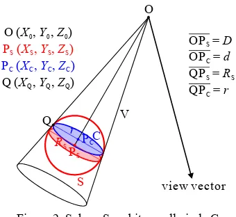
O
Figure 2. Sphere S and its small circle C
Consider that a right circular cone V with vertex
O O O
O X ,Y Z, in the camera coordinate system XY Z is tangent to the sphere S. The tangent line to the sphere S is a small circle C of the sphere S. The circumference of the ellipse on the image is the projected circumference of the small circle C. The small circle C is perpendicular to the axis of the cone V. Let r and
C C C C
P X Y Z, , in the camera coordinate system XY Z be the radius and the centre of the small circle C respectively. Consider that a point
Q Q Q
Q X ,Y Z, in the camera coordinate system XY Z is on the circumference of the small circle C.
The centre
C C C C
P X Y Z, , of the small circle C is represented as follows:
t t
are similar, the following equation is obtained:
S
Rearranging Equation (42) gives the following equation:
2
Substituting Equation (43) for Equation (40) gives the following equation:
C 2 S
equation is obtained: r D d
d r
(45)
Rearranging Equation (45) gives the following equation:
2
r d D d (46)
Substituting Equation (42) for Equation (46) gives the following equation:
2
Then the transformation T and the inverse of the transformation T are expressed as follows:
11 12 13
Because the transformation T makes the axis of the cone V parallel to the Z axis, the following equations are obtained:
31
Consider that the point
the following equation is obtained:Q Q Q Q
Substituting Equation (50) and Equation (51) for Equation (55) gives the following equation:
11 21
Substituting Equation (58) for Equation (57) gives the following equation:
11 12 13
Substituting Equation (60) for Equation (59) gives the following equation:
11 12 13
The small circle C transformed by the transformation T is a circle with radius r and centre PC (0, 0, −d) in the coordinate system X Y Z , and is perpendicular to the Z axis. Accordingly the small circle C in the coordinate system
X Y Z is represented as follows:
2 2 2 small circle C, the following equation is obtained:
2 2 2
Substituting Equation (61) for Equation (63) gives the following equation:
quadratic equation is obtained:2 2 2
Here substituting Equations (58), (53) and (41) for Equation (66) and rearranging gives the following equation:
Equation (65) shows an ellipse as which the sphere S with radius RS and centre PS (XS, YS, ZS) is projected onto the image. The centre
E E E
p x ,y , the semi-major axis a, the semi-minor axis b and the rotation angle of the major axis of the projected ellipse on the image take the following forms:
E 2
4.2 From an Ellipse Projected onto an Image
From now on we are going to derive an eccentricity of a sphere from an ellipse projected onto an image. First consider that a projected image of a sphere S onto an image is an ellipse E represented by the following equation:
2 2 2
p by using Equation (67), we can calculate the eccentricity (x, y) of the sphere S from the projected ellipse E by using Equation (72). Fortunately
C, C, C
p analytically. Since
X Y ZC, C, C
and r are linearly dependent,
X Y ZC, C, C
and r are represented using a scale factor s as follows:
from the projected ellipse E by substituting Equation (74) for Equation (72).Moreover substitution Equation (75) for Equation (46) and rearranging gives the following equation:
The radius RS of the sphere S can be obtained as follows:
XY Zof the sphere S is obtained as follows:S C
Equations (76), (77) and (78) contain the scale factor s. If the radius RS of the sphere S is known, we can estimate the scale factor s and finally we can know the centre PS(XS, YS, ZS) of the sphere S.
5. TRIAL CALCULATIONS OF ECCENTRICITIES We conducted trial calculations of eccentricities of circular targets and spherical targets mostly according to Luhmann’s simulation (2014). Since some errata were found in his paper, we modified some of imaging conditions. Therefore obtained results in the study were not necessary the same as Luhmann’s simulation results.
5.1 Imaging Scenario
The assumptions of an imaging scenario by a digital single-lens reflex (DSLR) camera are as follows:
(1) Camera
a) Image size: 4288 x 2848 pixels b) Unit pixel size: 5.5μm
b) A circular target and a spherical target are located at P4 (0 mm, 0 mm, -500 mm).
c) A circular target and a spherical target are located at P6 (360 mm, 240 mm, -600 mm).
d) The circular targets lie on a plane tilted relative to the image plane by angles = 20° and =10°.
Figures 3 and 4 show the semi-major axes a and the semi-minor axes b of ellipses on the acquired images. Figure 3 shows a and b against view angles of the camera where the circular target with RC = 5mm and the spherical target with RS = 5mm are located at P4. Figure 4 shows a and b against radii RC, RS of the circular target and the spherical target located at P6 where = 0°.
Figure 3. Semi-major axis a and semi-minor axis b
vs. view angle
Figure 4. Semi-major axis a and semi-minor axis b
vs. radius RC, RS where = 0°
5.2 Calculated Eccentricities
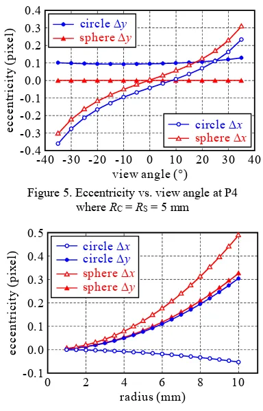
Figure 5 shows calculated eccentricities (x, y) against view angles of the camera where the circular target and the spherical target are located at P4 and RC = RS = 5mm. Figure 6 shows calculated eccentricities (x, y) against radii RC, RS of the circular target and the spherical target located at P6 where = 0°.
view angle (°)
-40 -30 -20 -10 0 10 20 30 40
Figure 5. Eccentricity vs. view angle at P4 where RC = RS = 5 mm
5.3 Discussion on Eccentricities on Digital Camera Images Figures 5 and 6 indicate that an eccentricity on an image acquired by the DSLR camera reaches almost a half pixel, which is considerably larger than the measurement accuracy of the centre of an ellipse on image (Luhmann et al., 2006b).
Although the obtained formulae demonstrate that a smaller target produces a smaller eccentricity, a smaller target reduces the measurement accuracy of the centre of an ellipse on image as Luhmann et al. (2006b) mentioned. The magnitude of the effect of eccentricities on an image acquired by a digital camera depends on the resolution of the digital camera. As the
resolution of a digital camera becomes higher, the influence of eccentricities becomes larger. Finally the correction of eccentricities would become unavoidable.
6. CONCLUSIONS
The general formulae calculating an eccentricity of a circle by using the focal length, the position, the attitude of the camera, and the radius, the location of a circle on a plane was derived. The paper shows a numerical method to estimate the eccentricity of a circle from the equation of the projected ellipse of the circle on an image as well.
Moreover the general formulae calculating an eccentricity of a sphere by using the focal length, the position, the attitude of the camera, and the radius, the location of a sphere was derived. As for a sphere the paper shows general formulae to calculate the eccentricity of a sphere from the equation of the projected ellipse of the sphere on an image.
REFERENCES
Hattori, S., Imoto, H., Ohnishi, Y., Ikeda, K., 2011. Chromatic Aberration Compensation for Industrial Vision Metrology, Technical report of IEICE, Multimedia and virtual environment, Vol. 110, No. 457, pp. 225-230.
Kaufmann, V. and Ladstädter, R., 2005. Elimination of Color Fringes in Digital Photographs Caused by Lateral Chromatic Aberration, Proceedings of CIPA 2005 XX International Symposium, Turin, Italy, pp. 403-408.
Luhmann, T., Hastedt, H., Tecklenburg, W., 2006a. Modelling of Chromatic Aberration for High Precision Photogrammetry, The International Archives for Photogrammetry and Remote Sensing, Dresden, Germany, Vol. XXXVI, Part 5, pp. 173-178.
Luhmann, T., Robson, S., Kyle, S., Harley, I., 2006b. Close Range Photogrammetry, Whittles Publishing, Caithness, UK, pp. 364-376.
Luhmann, T. 2014. Eccentricity in Images of Circular and Spherical Targets and its Impact to 3D Object Reconstruction, The International Archives of the Photogrammetry, Remote Sensing and Spatial Information Sciences, vol. XL-5, pp. 363-370.
Mallon, J. and Whelan, P.F., 2007. Calibration and Removal of Lateral Chromatic Aberration in Images, Pattern Recognition Letters, Vol. 28, No. 1, pp. 125-135.
Matsuoka, R., Sone, M., Sudo, N., Yokotsuka, H., Shirai, N., 2009. A Study on Location Measurement of Circular Target on Oblique Image, Optical 3-D Measurement Techniques IX, Vienna, Austria, Vol. I, pp. 312-317.
Matsuoka, R., Shirai, N., Asonuma, K., Sone, M., Sudo, N., Yokotsuka, H., 2011. Measurement Accuracy of Center Location of a Circle by Centroid Method, Photogrammetric Image Analysis, LNCS Volume 6952, Springer-Verlag, Heidelberg, Germany, pp. 297-308.
Verein Deutscher Ingenieure, 2002. Optische 3D-Messsysteme Bildgebende Systeme mit flächenhafter Antastung, VDI/VDE 2634 Blatt 2, Germany.