UAV DATA PROCESSING FOR LARGE SCALE TOPOGRAPHICAL MAPPING
W. Tampubolon*, W. Reinhardt
AGIS, Institute for Applied Computer Science, Universität der Bundeswehr München, Germany – (winhard.tampubolon, wolfgang.reinhardt)@unibw.de
Commission V, WG V/2
KEY WORDS: topographic mapping, map accuracy, UAV
ABSTRACT:
Large scale topographical mapping in the third world countries is really a prominent challenge in geospatial industries nowadays. On one side the demand is significantly increasing while on the other hand it is constrained by limited budgets available for mapping projects. Since the advent of Act Nr.4/yr.2011 about Geospatial Information in Indonesia, large scale topographical mapping has been on high priority for supporting the nationwide development e.g. detail spatial planning. Usually large scale topographical mapping relies on conventional aerial survey campaigns in order to provide high resolution 3D geospatial data sources. Widely growing on a leisure hobby, aero models in form of the so-called Unmanned Aerial Vehicle (UAV) bring up alternative semi photogrammetric aerial data acquisition possibilities suitable for relatively small Area of Interest (AOI) i.e. < 5,000 hectares. For detail spatial planning purposes in Indonesia this area size can be used as a mapping unit since it usually concentrates on the basis of sub district area (kecamatan) level. In this paper different camera and processing software systems will be further analyzed for identifying the best optimum UAV data acquisition campaign components in combination with the data processing scheme. The selected AOI is covering the cultural heritage of Borobudur Temple as one of the Seven Wonders of the World. A detailed accuracy assessment will be concentrated within the object feature of the temple at the first place. Feature compilation involving planimetric objects (2D) and digital terrain models (3D) will be integrated in order to provide Digital Elevation Models (DEM) as the main interest of the topographic mapping activity. By doing this research, incorporating the optimum amount of GCPs in the UAV photo data processing will increase the accuracy along with its high resolution in 5 cm Ground Sampling Distance (GSD). Finally this result will be used as the benchmark for alternative geospatial data acquisition in the future in which it can support national large scale topographical mapping program up to the 1:1.000 map scale.
* First author
1. INTRODUCTION
Geospatial information nowadays has turned into a primary need in human lives. This characteristic leads to a massive development of geospatial industries in parallel with the invention of new technologies in an open and attractive worldwide market. Heavy competition from different platforms, sensors, and techniques is coming up as a logical result of geospatial demand explosion around the globe.
1.1 Research Background
Under the recent Act.Nr.4/yr.2011 about Geospatial Information in Indonesia, the Geospatial Information Agency of Indonesia (BIG) must take responsibility to provide official topographic map data which shall cover 1.9 million square kilometers land area of Indonesia which is approx. 4 times the land area of Germany.
This monumental governmental act was really an opportunity and a challenge for the geospatial data development especially to support the economic development in Indonesia. In that case, the proper technologies and methodologies have to be integrated to speed up the huge topographic mapping program in various map scales specifically for large scale mapping i.e. equal or larger than 1:10.000.
As an example for the 1:5.000 map scale, the number of single map sheets in a 2.3 by 2.3 km to be produced is 379.014 (Table 1). Giving 10 % priority for cities or built areas, it will end up in 38.000 map sheets. A normal capacity for the annual production of the 1:5.000 map scale is 100-200 map sheets. It means without any acceleration activity as a breakthrough, the 1:5.000 topographic maps of Indonesia will be once covered in 190-380 years.
Map scale (1:M)
Map Coverage (Length×Width)
in Km
Map Sheets (Numbers)
Availibility (%)
1 2
1,000,000 500,000
668 × 442 334 × 221
37 103
0 0
3 250,000 167 × 111 309 100
4 100,000 55.6 × 55.6 1,245 0
5 50,000 27.8 × 27.8 3,899 62
6 25,000 13.8 × 13.8 13,020 14
7 10,000 4.6 × 4.6 91,547 0.7
8 9 10
5,000 2,500 1,000
2.3 × 2.3 1.15 × 1.15 0.58 × 0.58
379,014 880,206 2,729,319
0.06 0 0 Table 1 Indonesian Topographical Maps Volume
Moreover as one of the vulnerable countries around a disaster prone area - sometimes called ring of fire - Indonesia really needs sophisticated seamless topographical map data for better disaster preparedness and quick emergency response. The International Archives of the Photogrammetry, Remote Sensing and Spatial Information Sciences, Volume XL-5, 2014
Topographical maps are essential because they contain basic geospatial features including earth surface terrain information with respect to its proper geometrical accuracies.
Utilization of geospatial enabled data using topographic map as a basic reference is mandatory in order to provide accurate quick emergency response, often called rapid mapping. This critical aspect has initiated worldwide cooperation under International Charter on Space and Major Disasters, in which the utilization of satellite based data including Very High Resolution Satellite (VHRS) data, will be really provided immediately in the period of major disasters around the globe.
The massive development of space remote sensing technologies enhances both spatial and spectral resolution to enable geospatial data production in order to provide the high end Indonesian Spatial Data Infrastructure (Ina-SDI). The advantage of this space segment is the cut-off of bureaucratic problems during the security clearance procedure.
In this context, heavy competition in terms of geospatial data source provision is really an issue now especially in the recent years while aerial data acquisition progresses were stagnant due to its high costs. Looking closer at this opportunity, it will be an advantage if the integration between space borne and alternative technologies can support each other to accelerate topographical map production.
Some recently upcoming alternative technologies for geospatial data production give a high resolution solution to the generation of orthophotos and digital elevation models (DEM). Especially the utilization of Unmanned Aerial Vehicle (UAV) has found its way to the professional market in parallel with its hobby communities which are growing rapidly for different purposes.
At a glance, UAV appears as a breakthrough which can combine interesting high resolution data acquisition with relatively simple and cheap platforms in comparison with conventional airborne campaigns (Neitzel, 2011). By flying on low altitude, the captured UAV photos provide the geospatial objects in high details and full color. On the other hand side, the complicated regulations/restrictions in many countries for aerial mapping survey is still somehow endorsing people to apply UAV technology without significant legal limitation.
On the other hand, after the successful launch of the next complementary generation of German TerraSAR-X-add-on Digital Elevation Measurement (TanDEM-X) satellite in 2010, this ambitious project will hopefully provide worldwide DEM in a resolution of 10 m in much similar way as the SRTM global Digital Elevation Model (DEM) provision in 2001. The advent of TanDEM-X with a bi-static interferometry aims on providing HRTI-3 global DEM which has the accuracy within 10 m absolute horizontal (circular error) and 10 m absolute vertical (linear error) at 90% level of confidence.
This type of geospatial data source will be potentially used for large scale topographical mapping only up to the 1:10.000 map scale. For larger map scales the integration with UAV data is assumed as a potential solution especially in order to improve the absolute accuracy of elevation data.
The major advantage of using satellite-based RADAR data is the relatively weather independence and free security clearance procedure. However, using RADAR data for large scale topographic mapping is still constrained especially for object
interpretation and geometric accuracy matter. In order to overcome this drawback, the integration between RADAR and optical sensor i.e. UAV imageries is assumed as a potential solution.
Bridging the distance from those two kinds of sensors will be created by establishing a data processing chain in rapid mapping where the quick response and high accuracy can be achieved simultaneously. This UAV data processing research aims to integrate RADAR and optical imagery by using high accuracy datasets as a reference into the established geodatabase in BIG.
In order to guarantee the necessary height accuracy, UAV data processing must be supported by ground segment data i.e. Ground Control Points (GCP) which refers to the national geodetic and geodynamic reference network. However GCP are always an issue with regards to the geometric accuracy (Tampubolon, 2012) and hence the project costs. Synchronizing GCP measurements can presumably increase project efficiency without reducing geometric accuracy.
1.2 Methodology
This paper will mainly concentrate on the geometric accuracy of orthophotos and DEMs. In order to verify and identify the geometric accuracy, it is necessary to use valid and independent geospatial data source and techniques with certain quality.
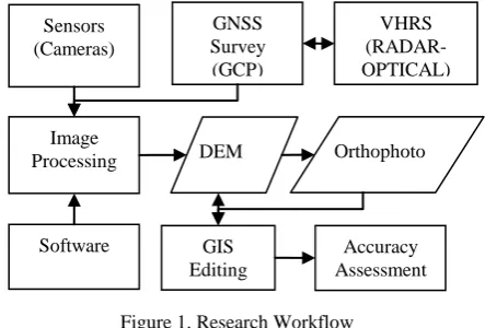
Basically there are 3 aspects to be evaluated for this UAV data processing namely Sensor, Image Processing Software and GCP schemes (Figure 1). Combination among them will identify the best possible geometric accuracy for large scale topographical mapping purpose.
1.3 Area of Interest (AOI)
Borobudur temple, the biggest temple in Indonesia is located in the southern part of Central Java Island, well known as one of
the preserved UNESCO’s world heritage1.
Borobudur is classified as Buddhist temple which was constructed within the 8th and 9th centuries. Due to its location in central Java, it can be reached easily and therefore attracts many tourists from all over the world. It consists of three different major tiers/components. First is the pyramidal base with five concentric square terraces. Second one is the conical trunk with three circular platforms. The third is located at the top and appears as a monumental stupa.
1
http://whc.unesco.org/en/list/592 (last accessed 06.05.2014) GNSS
Processing DEM Orthophoto
GIS Editing
Accuracy Assessment
Figure 1. Research Workflow The International Archives of the Photogrammetry, Remote Sensing and Spatial Information Sciences, Volume XL-5, 2014
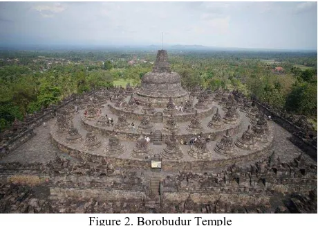
Basically its walls and balustrades are decorated with fine low reliefs, covering a total surface area of 2,500 m2. There are 72 openwork stupas around the circular building platform (Figure 2). Each of it contains a statue of the Buddha. Fortunately for the preservation act, the monument was restored in the 1970s by
UNESCO’s support.
Figure 2. Borobudur Temple
As a big picture, the national strategic area of Borobudur temple covers some villages in a North East – South West direction which covers approximately area of 2,700 hectares. Basically the terrain condition of the study site is classified as medium undulated without any extreme slope area.
In the development context, it is prioritized by the stakeholders to accomplish the detail spatial planning over that national strategic area. Therefore in 2012, the utilization of Very High Resolution Satellite (VHRS) imageries has been applied in order to achieve at least proper planimetric accuracy for large scale mapping by performing orthorectification mechanism supported by GNSS measurements.
Detail AOI has been selected under the assumption that the temple structure is always preserved as a conservation site. Therefore it makes sense to use GCP data from different time series for data production and validation.
1.4 Research objectives and motivation
The main objective of this research is to provide a kind of standard procedure for UAV data processing in the context of large scale topographical mapping. By comparing UAV data acquired from different sensors, geometrical accuracy of the end product can be estimated before the mission.
With respect to other geospatial data sources i.e. VHRS, the UAV technology can be consolidated in order to avoid project inefficiency especially in the scope of GCP measurements. Therefore this paper will also demonstrate a project synergy in order to achieve optimum geometric accuracy with minimum redundancy measures.
The main goal of this paper is to give recommendations for a proper usage of UAV technology for an alternative large scale topographical mapping in the special case of Indonesia. It includes the GCP requirements as well as the processing schemes based on certain assessment standards in the context of large scale topographical mapping in Indonesia.
2. DATA ACQUISITION
2.1 Sensor platform
Nowadays, UAV technology has improved its performance progressively in all components, including instrumentation control and automation. Mapping and surveillance are the two most prominent purposes of UAV campaign.
With respect to the carrying capacity, usually UAV platforms use digital non-metric camera as a main sensor especially for mapping purposes.
Figure 3. Sensor Platform
For image capturing from around 200 m Above Ground Level (AGL), there is no need for specific weather conditions i.e. clouds are not preventing a mission. However very often, wind blows leads to difficulties for stabilizing the flimsy fuselage during the data acquisition.
Data acquisition has been done using Skywalker Condor with wingspan 1880 mm (Figure 3). This platform is capable enough to carry the digital cameras used in this project, either Canon S-100 or Sony NEX-7 including the necessary power sources during the campaign.
Figure 4. Camera (Sony NEX7/left, Canon S100/right)
In general, Sony NEX7 has a more suitable specification than Canon S100 especially in the image resolution which usually indicates better performance (Table 2).
Camera Sony NEX7 Canon S100
Weight 400 g 198 g
Resolution 24 Mpixels 12 Mpixels
Focal length 18 - 55 mm 24 -120 mm
Optical zoom 1.5 times 5 times
Sensor size 23.5 × 15.6 mm 7.44 × 5.58 mm
Image size ± 7.75 Mb ± 3.5 Mb
Table 2. Camera specifications
2.2 Reference Frame
There are two types of fundamental geospatial data which shall be used as a reference for thematic or general spatial purposes. Those basic geospatial data determine overall geospatial The International Archives of the Photogrammetry, Remote Sensing and Spatial Information Sciences, Volume XL-5, 2014
accuracy in order to support “One Map” policy in Indonesia.
This policy restricts any thematic geospatial users to refer on fundamental geospatial datasets e.g. topographic map, coastal map and national sea map.
The first component is the topographical map itself which will be provided in the Indonesian Spatial Data Infrastructure (Ina-SDI). This type of reference frame must be used as the official reference for both the content and positional (geometrical) aspect.
Secondly is the geodetic and geodynamic control network which can be considered as Indonesian geospatial reference frame (SRGI). As a main core component, this official network mainly establishes reference stations serving different kind of users including topographical map producers. The question about availability is always raised regarding to the reference control network (Figure 5).
Figure 5. CORS Station Network (courtesy of BIG)
3. DATA PROCESSING
This paper describes UAV photo processing following a photogrammetric approach by using GCP from GPS measurements and stereo optical compilation. It is concentrated on the data processing performance in order to obtain proper geospatial data sources for large scale topographical mapping.
3.1 GPS data
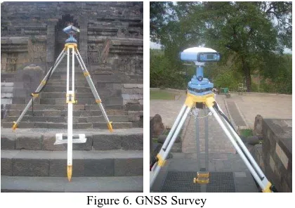
GPS survey is aiming on providing the representative GCP network with a good spatial distribution over the Borobudur Temple. In principal, GCP measurements will cover two main purposes of the field survey. The first one is to check the quality of the acquired photograph including photo orientation and the latter one is to establish accurate GCPs network for orthorectification purpose.
During the UAV campaign, 6 new GCPs have been measured using geodetic GPS double frequency L1/L2 with good distribution covering the AOI. Implementing rapid static differential positioning, every GCP must be measured not less than 30 minutes in order to get sub centimetre accuracy.
In addition to the rapid static measurements, some more points i.e. 31 Independent Check Points (ICP) have been measured utilizing Continuous Operating Reference System (CORS) service for elevation accuracy assessment purpose. These measurements also have provided synchronization of positional reference between static and real time modes which are in the range below 1 m accuracy. Hence it will ensure the consistent positioning reference both for UAV data processing and accuracy assessment.
Figure 6. GNSS Survey
GCP selection has been performed in the field by defining points which can be identified clearly in the photo with high certainty. Suitable examples of this regular form features are the building edge, the statue and the tile objects (Figure 6). The point selection has to be done by extracting point objects from regular form features within the minimum size of 2 times photo resolution i.e. 10 cm (Figure 7).
Figure 7. GCP identification in photo
In the context of technical implementation purpose, there are 4 options used to process GPS data:
1.Near Fix Reference
GPS measurement refers to the nearest available CORS operated by BIG which is located in Magelang city (CMGL), around 14 km northern of the AOI. This CORS can deliver GPS raw data in the highest resolution i.e. up to 1 second interval time.
2.Precise Point Positioning (PPP)
PPP is an online application for GNSS data post-processing that allows users to submit raw GPS data via internet and receive data with enhanced positioning precisions within a global reference frame, based on precise GNSS Orbit and Clock information,.
3.Absolute Positioning
The measurement is performed independently without any reference station consideration.
4.Far Fix Reference
GPS measurements refer to the CORS operated by BIG which is located in BIG office (BAKO), around 400 km from the AOI.
GPS measurement schemes can lead to the proper field data collection and processing methodology with respect to the accuracy requirement. As a compromise, PPP brings reliable solution independently from the reference network coverage despite of its sub-meter accuracy (Table 3).
GCP_ID Near Fix Reference
(m)
PPP (m)
Far Fix Referenc e (m)
Absolute Positioning
(m)
BR04 0.073 0.032 3.745 2.471
BRB1 0.021 0.417 7.520 11.048
BRB2 0.030 0.204 0.698 4.068
BRB3 0.038 0.407 8.004 8.210
BRB4 0.015 0.033 3.283 0.670
E000 0.037 0.422 3.538 2.413
Acc. 0.069 0.521 8.755 10.279 Table 3. GPS Measurements Accuracy
3.2 Orthorectification and DEM production
In this paper, hybrid orthorectification has been introduced as a mathematical solution to reconstruct remote sensing data including UAV survey campaign by combining planimetric and terrain aspect of earth surface from VHRS. Applying the collinearity approach to the image data leads to:
(1)
(2)
where (X,Y,Z) are the object ground coordinates, (Xs,Ys,Zs) are the projection center coordinates, (x0,y0) are the coordinates of principal point, (x,y) are the image coordinates, and f is the focal length of the sensor. The nine parameters those have to be calculated are a1, a2, a3, b1, b2, b3, c1, c2, c3.
For image processing two different photo processing software systems have been used. The first one is PCI Geomatics which has a long experience in photogrammetric techniques for aerial or satellite imageries data processing. The other software is Agisoft Photo Scan which is relatively new to the market focusing on computer vision technology approaches.
Figure 8. Camera Calibration information
The major distinction between the PCI Geomatics and Agisoft software is related to the camera calibration. Eq.1 and Eq.2 require focal length and principal point location which can be provided from camera calibration parameter. Hence in PCI Geomatics, this calibration parameter is a mandatory pre-requisite for subsequent image processing steps (Figure 8). In contrast Agisoft Photo Scan can proceed without camera calibration empowered by a robust image matching algorithm.
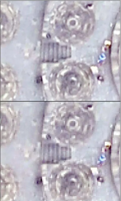
The final Ground Sampling Distance (GSD) has been selected to 5 cm both for DEM and orthophoto. This resolution allows that during digitation object patterns with optimal zooming (Figure 9) can be recognized and a high accuracy can be reached in the end.
Figure 9. Comparison between 5 cm (upper) and 10 cm (lower) GSD
At the first place, VHRS imagery with planimetric accuracy in 2.4 m has been used as the reference image for orthorectification of UAV data (Figure 10). Certainly it requires elevation data in which it can be extracted from RADAR space borne data (TerraSAR-X).
Currently, this RADAR space borne data has just been used for the medium scale topographical mapping e.g. up to 1:25.000. By using this approach, provision of DEM from UAV will bring a potential solution for large scale topographical mapping i.e.1:5.000.
Figure 10. GCPs from VHRS
In order to verify the result, GCPs from GPS measurement can be used as the best possible reference data with sub meter accuracy (Figure 11). At the end, those GCPs also have been used in the final orthorectification subsequently.
Figure 11. GCPs from GPS Survey
3.3 GIS data production
The involvement of Geographical Information System (GIS) in this research is mainly related to the vector data production from both orthophotos and DEM. Vector data is the key performance indicator for overall output or end product as it will be used in the subsequent topographical mapping step. The performance will be evaluated based on the correctness and consistency during feature compilation.
Normally, topographical features are produced by using stereo working stations (Figure 12). Based on the official regulation (Act) in Indonesia as implemented in the technical specification, there are 8 different themes/layers involved in the topographical mapping:
1. Shoreline 2. Hypsography 3. Hydrology
4. Geographical Names (Toponym) 5. Administrative Boundary 6. Transportation and Utility 7. Building and Public Facility 8. Land Cover
Figure 12. GIS data production
4. ACCURACY ASSESSMENT
4.1 Assessment Procedure
An empirical method has been used as first initial step in order to obtain the geometric accuracy level of UAV data in 5 cm resolution. Assuming that GCPs data integration in the orthorectification mechanism will increase the accuracy and minimize some inconsistencies, large scale topographical mapping must be performed properly to achieve geometric accuracy in the scope of National Standard for Spatial Data Accuracy (NSSDA) with 95 % confidence level.
Certainly, the proper topographical map data is required as a valid reference source. Therefore the official topographical map is used as the reference. This 1:5.000 large scale topographical map has been produced in a year of 2012 by performing VHRS orthorectification mechanism. Only hypsographic component is still incomplete for the large scale mapping using VHRS. As already demonstrated by Zebker, 1994, in a condition where accurate DEM does not exist, the statistical error can be computed to ensure theoretical accuracy.
Product Post
spacing (arc-sec)
Post spacing
(m)
Rows/columns (1x1 tile)
File size (MB)
DTED Level 0 30 arc-sec
approx. 1,000
121/121 .03
DTED Level 1 and DEM 1°
3 arc-sec approx. 100
1201/1201 2.8
DTED Level 2 1 arc-sec approx. 30
3601/3601 24.7
DEM 7.5’ --- true 30 (in 7.5 minute
tiles) HRTI Level 3 0.4
arc-sec
approx. 12
9001/9001 309
HRTI Level 4 0.2 arc-sec
approx. 6
18001/18001 1236
HRTI Level 5 0.04 arc-sec
approx. 1
90001/90001 30,900
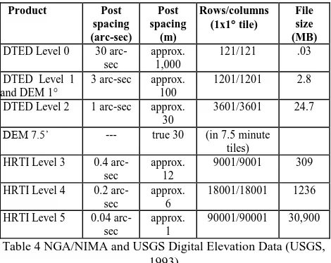
Table 4 NGA/NIMA and USGS Digital Elevation Data (USGS, 1993)
HRTI stands for High Resolution Terrain Information, while DTED stands for Digital Terrain Elevation Data. In order to get better accuracy, HRTI will be stored as 4-byte (32-bit) in a case that elevations can be stored in real numbers instead of integers. However, this will also double the file size compared to using 16-bit data. Currently HRTI can usually be collected using an The International Archives of the Photogrammetry, Remote Sensing and Spatial Information Sciences, Volume XL-5, 2014
airborne IFSAR (Interferometric Synthetic Aperture Radar) platform.
4.2 Geometric Accuracy
With respect to the geometric accuracy, the assessment method namely National Standard for Spatial Data Accuracy (NSSDA) has been introduced for geospatial consistency checking (FGDC, 1998). The basic idea behind this method is the detection of blunders from a given data set and the derivation of a statistical model.
Data resolution consideration (similar to image pyramids) can be applied to generate a corresponding assessment model in a coarse to fine approach using two different GCP schemes. First is using GCPs from the existing project while the other is adding new GCPs during the UAV campaign. This method is based on linear prediction to detect the smallest object deviation on the corresponding ground resolution of the images.
The NSSDA uses Root Mean Square Error (RMSE) to estimate positional accuracy. RMSE is the square root of the average of the set of squared differences between dataset coordinate values and coordinate values from the reference data for identical objects.
The RMSE can be calculated by the following equation (FGDC, 1998) for each corresponding object in the different datasets i.e. between the evaluated data and the reference data. The examination focuses on the point features since the involved spatial data are assumed to be produced with different resolutions and various acquisition methods.
n
where: RMSEx = Root Mean Square Error in x axis direction RMSEy = Root Mean Square Error in y axis direction RMSEr = Horizontal (2D) Root Mean Square Error (XRei, YRei) = Coordinates of common points i in the reference dataset
(XChecki, YChecki) = Coordinates of common points i in the evaluated dataset
n = number of common points
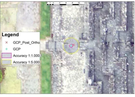
The accuracy is given in ground distances at the 95% confidence level. It means that 95% of the positions in the dataset will have an error with respect to true ground position that is equal to or smaller than the reported accuracy value. The reported accuracy value reflects all uncertainties, including those introduced by geodetic control coordinates, feature compilation, and final computation of ground coordinate values in the end product (Figure 13).
Figure 13. Planimetric Accuracy
Based on National Mapping Accuracy Standard (NMAS), the horizontal tolerance accuracy can be seen in Table 5. Differently to NSSDA accuracy, NMAS introduced a circular error in 90 % level of confidence which is more moderate than NSSDA in what so called Circular Map Accuracy (CMAS) as
Table 5. NMAS Horizontal Accuracy Tolerance
National Mapping Accuracy (NMA) standards allow an absolute Horizontal (circular error) and a vertical (linear error) at 90% level of confidence. In terms of elevation data for 1:5,000 topographical mapping, it means that 90 % of spot elevations must be within 4.25 m of their true horizontal position and 90% measured vertical elevation shall be within 1.25 m (half of the contour interval) of the absolute height.
In order to obtain a proper statistical analysis and to avoid misinterpretations in the accuracy assessment, the following assumption have been taken:
1. GPS Rapid static positioning for GCP measurements provide coordinates in centimeter level accuracy;
2. Operator ability to prick the GCP points in the photo will be 2 times image resolution = 10 cm.
This paper has identified absolute geometric accuracy of the outputs by using GIS approach from different software, cameras and GCP schemes.
Table 6. Geometric accuracy using S100 Camera The International Archives of the Photogrammetry, Remote Sensing and Spatial Information Sciences, Volume XL-5, 2014
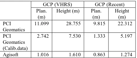
Inaccurate calibration camera in PCI Geomatics gives more significant geometric deviation in NEX7 rather than S100. It is also confirmed by the ratio between planimetric and vertical accuracies in Agisoft. S100 gives 1.081/0.967 (Table 6), where NEX7 gives 0.863/1.274 (Table 7).
GCP (VHRS) GCP (Recent) Plan.
(m)
Height (m) Plan. (m)
Height (m) PCI
Geomatics
11.099 28.755 9.815 22.312
PCI Geomatics (Calib.data)
2.742 7.530 1.333 5.197
Agisoft 1.016 1.610 0.863 1.274
Table 7. Geometric accuracy using NEX7 Camera
5. CONCLUSIONS
Topographic maps with absolute NSSDA errors of 1 m (accuracy) can be achieved with full control GCP from the UAV campaign using non-metric digital pocket cameras, providing relatively inexpensive measures in order to generate DEM sufficient enough for Large Scale Topographical Mapping requirements in Indonesia.
This research has shown the significant geometrical improvement of UAV photo data processing by implementing integration mechanism with VHRS imagery in which appropriate for 1:2.500 planimetric accuracy. However for the DEM, it is necessary to implement full control i.e. 8 GCPs / model in order to fulfil 1:5.000 topographical mapping accuracy. On this level of geometric accuracy, Precise Point Positioning (PPP) suffices GCP accuracy requirements and hence can reduce time, cost and reference station dependency.
ACKNOWLEDGEMENTS
We would like to acknowledge Geospatial Information Agency of Indonesia (BIG), Expert group on Remote Sensing, Geographic Information Science (KK-INSIG) ITB and Borobudur Conservation Center (BKB) for establishing good cooperation and providing full access to the UAV data, GPS raw data of reference station (CORS) during the campaign as well as necessary processing software licenses (PCI Geomatics and Agisoft Photo Scan).
REFERENCES
USGS, 1993. Data User Guide, Digital Elevation Models, Virginia, USA,
http://agdc.usgs.gov/data/usgs/geodata/dem/dugdem.pdf (28 Apr.2014).
FGDC, 1998. Geospatial Positioning Accuracy Standards Part 3: National Standard for Spatial Data Accuracy (version 2.0), Washington, D.C., FGDC-STD-001-1998: Federal Geographic Data Committee, pp.3-4
Zebker, H., 1994. Accuracy of Topographic Maps Derived from ERS-1 Interferometric Radar. IEEE Transaction on Geoscience and Remote Sensing Vol. 32, No.4, pp.823-836.
Neitzel, F., 2011. Mobile 3D Mapping with a Low-cost UAV System. International Archives of the Photogrammetry, Remote
Sensing and Spatial Information Sciences, Zurich, Switzerland, Vol. XXXVIII-1/C22.
Tampubolon, W., Hendrayana, E., 2012. Orthorectification of Very High Resolution Satellite Imagery in the context of detail spatial planning purposes. In: International Conference of Applied Geoinformatics for Society and Environment (AGSE), Johor Bahru, Malaysia
http://www.applied-geoinformatics.org/downloads/AGSE2012_2nd_edition_2012_ 08_17.pdf (28 Apr. 2014).