A Model-Based Approach To Requirements Analysis
Eva Geisberger, Johannes Gr¨unbauer, and Bernhard Sch¨atz
Technische Universit¨at M¨unchen, Institut f¨ur Informatik
Boltzmannstr. 3, D-85748 Garching bei M¨unchen, Germany
Abstract
A major task in designing systems development is the systematic elaboration of functional system requirements and their integration into the environment of the overall technical system. The main challenge is to handle the ver-satile tasks of coordinating the communication and con-solidation of the various stakeholder requirements of the different involved diciplines and derive a common defini-tion of the system behavior, which is appropriate to the problem. The problem- and customer-related product def-inition must be consolidated with and integrated into the manifold requirements of the functional and technical sys-tem design. Accordingly, the model-based requirements analysis and system-definition presented here defines a well-structured modeling approach, which provides a ba-sic model of RE work products (RE Product Model) and systematically guides the goal-oriented formulation and ad-justment of the different stakeholder-requirements by using functional system views and descriptive specification tech-niques. Thus it allows a clear specification of a consis-tent and complete system design. The central steps of this approach are implemented in a requirements management (RM) tool prototype calledAUTORAID.
1. Introduction
The definition of the initial system specification is the source of the most crucial development errors in a devel-opment process. To avoid these error, the formulation of a requirements- and systems-specification has to be the result of systematic coordination between the different demands of the stakeholder, the customers and users (users, market-ing, distribution, service, product lines) on the one hand, and the technical disciplines like mechanics, electronics and computer science on the other hand. Thus we have to
• analyze the problem and the goals of the product
de-velopment,
• systematically elaborate the functional requirements
and properties, as well as the integration of the system
including all its interfaces, and have to describe them precisely. Furthermore, we have to
• elaborate and analyze the manifold constraints which
result from the different objectives and the integration into the products and systems, and to
• include the resulting requirements regarding design
and realization of the system in an early phase into the specification of the system. As well, we have to con-sider constraints to the functions, the behavior and the technical realization of the system.
2. Model-Based Requirements Engineering
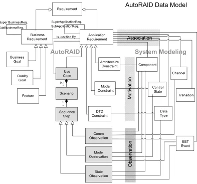
The central approach of model-based requirements en-gineering (RE) is the introduction of a common model of specification products – the RE Product Model (Fig. 1). It drives the interdisciplinary elaboration and coordination of the requirements with the aid of elementary models and constraints. It’s substantial elements are the definition of goalsandstrategic constraints, the resultingfunctional re-quirementsandgeneral conditionsfor the system to be de-veloped from the customer’s point of view, and the precise specification of the system concept with itsdetailed system requirements andconstraintsto interfaces and the further design within the disciplines software, mechanics and elec-tronics.
Figure 1. Structure of the RE Product Model
have to be motivated from business goals. They drive the refinement of the ”high-level” requirements and the design of thedetailed system concept, which is systematically de-rived and specified by functional models.
The modeling concepts provided by the approach de-scribe via five basic ”modeling views”: scenario views (models of the use processes and scenarios), structural views(environment model, system boundaries, function hi-erarchy), interaction views, data views and behavioral views. By the mapping of these views onto a uniform sys-tem model, conditions regarding consistence between the views are introduced, which can be used for the review and adjustment of the elaborated requirements- and system-models. Requirements of different stakeholders are mapped on the modeling elements of the system views in a step-wise fashion, are structured, analyzed, and completed with the aid of the underlying system model as well as the consis-tency conditions. The interactive use of descriptive specifi-cations techniques is substantial for the successful and goal-oriented adjustment of the functional system views.
With the help of this structured modeling approach, a basis for communication and adjustment for the interdis-ciplinary elaboration, validation, and analysis of a consis-tent and complete requirements- and system-specification is found. The RE product model allows the common goal-oriented and traceable definition of requirements and serves as a standard for quality and progress control of the specifi-cation.
3. Requirements Management – The A
U-TO
RAID Tool
The main concept of model-based requirements engi-neering are reflected in the product model of the AU
-TORAID1-tool (Fig. 5), describing the elements of a sys-tem specification and their relation. It contains informal
1AUTOFOCUSRequirements Analysis Integrating Development
Figure 2. Iterative Process Model in AU
-TORAID
requirements (in form of business and application require-ments), classified constraints (architectural, modal, and data type), uses cases (including scenarios as sequences of ob-servations), as well as their relation (in form of association, motivation, and observation) to the concepts of the system model (like component, control state, or EET event).
As explained in the following sections, it guides the mul-tidisciplinary RE activitiesRefinement,Classifying, Model-ing, andAnalysis, which have to be elaborated in an iterative steps, of requirements analysis and system designs. This iterative feedback loop of refining and completing require-ments in AUTORAID is shown in Fig. 2. The stepStarting and getting requirementsshows the steady input of require-ments into the process. The activitysystem design shows the adjustment and specification of models/drafts during the whole RE-process.
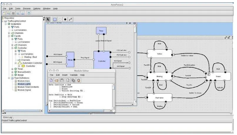
AUTORAID is integrated into the specification tool AUTOFOCUS[1, 3], and uses its formally founded system views and graphical description techniques (Fig. 3), includ-ingSystem Structure Diagrams(SSDs, upper left window) describing the structure of a system, with its components, interfaces, and communication paths;System Structure Dia-grams(STDs, right window) using extended finite automata to describe the behavior of a component in an SSD; Data Type Definitions(DTDs, lower left window) specifying the data types used in the model [9]. Extended Event Traces (EETs, right-hand side of Fig. 9) finally make it possible to describe exemplary system runs, similar to MSCs [5]. The verification and simulation support supplied by AUTOFO
-CUScan be used to validate the requirements.
Com-Figure 3. System Views and Representation Techniques inAUTOFOCUS
ponents, Ports andChannels) and system behaivior (e. g. Sequences,ControlStatesandTransitions).
In the following, we sketch the process of the model-based requirements engineering regarding to the method-ological steps of AUTORAID in Fig. 2. A detailed descrip-tion can be found in [2].
3.1. Getting and Refining Requirements
The requirements engineering process starts with the elicitation of requirements. Common techniques to acquire them are structured workshops or interviews [4, 6]. In the most straightforward case requirements are entered into AUTORAID. To create a new requirement, attributes like title,description,status,priority, etc. have to be identified. Fig. 5 shows the concepts within the data model and Fig. 6 shows the concept by the AUTORAID user interface repre-sentation. The project tree (lhs. in Fig. 6) shows the refine-ment structure of requirerefine-ments. Additionally, requirerefine-ments source documents and their contexts are integrated into the Analysis-tree.
Besides directly creating new requirements, require-ments can be created out of asource documentworked out by a source context (meetings, telephone calls, etc.). By “cut-and-paste”, requirements can be conveniently created and traced to the source by keeping the link to the corre-sponding part of the document. AUTORAID supports di-rect integration of structured requirements documents, e.g, generated by DOORS.
Requirements - distinguished by their unique identifier and title – are added to theanalysis-branch of aproject-tree.
(cf. Fig. 6, lhs.).
According to the goal-oriented refinement of require-ments,ApplicationRequirementscan be derived from goals (BusinessRequirements) in AUTORAID. From Applica-tionRequirementsfurtherSubApplicationRequirementscan be derived. Vice versa, it is possible to analyze elicited requirements according to their contribution to the goal-achievement, and to structure them in refinement-hierarchies. Fig. 5 shows the corresponding functionality within the AUTORAID data model by theIs Justified By re-lation betweenBusinessRequirementsandApplication Re-quirements, theirSuper-andSub-relations, and by the dif-ferent forms of structuring requirements intoUseCasesor Constraints. The corresponding menue functions are shown in Fig. 7 (Edit,Classify to,Refine2,CreateandAssociate),
and the resulting refinement-structure is represented by the ”‘goal-trees”’ within the Requirements- tree. (All Appli-cationRequirements must be subordinated to BusinessRe-quirements). The refinement relations are also shown in the description of a requirement (right hand side of the AUTORAID window), listing directSuperrequirementsand Subrequirements.
3.2. Classification and Modeling of
Require-ments
According to the classifying schema of requirements, in AUTORAID requirements can be refined and specified by UseCases or Constraints. UseCases are processes3,
2The sub-menu functions ofRefineareEdit Refinement,Copy,Move,
InsertandRevers
Figure 4. Some Concepts used inAUTOFOCUS
!
" #
$
! $
%% % !
! &
' ( )
( )
Figure 6.AUTORAIDUser Interface
or required system functions or services, which have to be specified in a more detailed way. Constraintsare the specification of the system environment or the request for system requirements like architectural-, state- or interface-requirements.
Constraintsare separated into (Fig. 5)
• ArchitecturalConstraints– requirements regarding the
structure of the system to be developed, and its envi-ronment. Here, the components, their interfaces and the communication channels can be constituted (struc-tural view).
• ModalConstraints – modes of the application. The
states and the transitions between them can be defined (state-oriented behavioral view).
• DTDConstraints– data type definitions of the
commu-nication within the system or a state variable of the modeling of the behavior (data view).
The initial point for the elaboration of functional require-ments and system designs is the comprehensive modeling and analysis of both the business- and use-processes of the system. This is done by using ofUseCase- andScenario -modeling. Starting with the informal use of graphical mod-eling techniques, like activity diagrams in UML, the main application-process steps and use functions of the system are defined, and modeled within AUTORAID, in an itera-tive way. This procedure, as well as the detailed analysis
and modeling of the scenarios and system interactions are described in Sect. 3.2.3.
Classifying requirements into Use Case/Scenario, Architectural-,Modal-orDTD-Constraintsis the first step towards detailed system modeling. By and by, the com-ponents of the system environment and the system bound-aries are defined, the interfaces are sketched and the system functions/services, which have to be developed, are identi-fied. For the purpose of this construction and detailed spec-ification of the component- and system-behavior, in AU
-TORAID theMotivation-andAssociation-function are con-ceived.
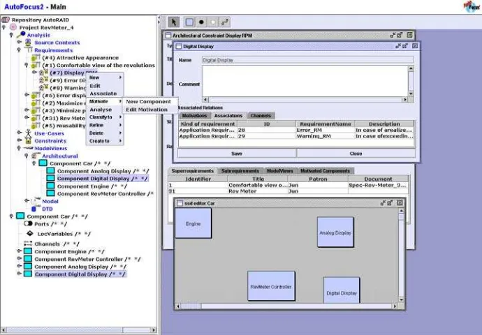
3.2.1 Motivation
The Motivation-function in AUTORAID is used to cre-ate model elements in AUTOFOCUSout of theContraints -requirements. Fig. 5 shows the corresponding construction relation (Motivation) between the requirements for dedi-cated model elements (Constraints) and the system ele-ments to be modeled (Component, Channel, State, Tran-sitionSegment,Type) of the system-specification-tool AUT
-OFOCUS.
mod-Figure 7.Motivation-andAssociation-Functions inAUTORAID
eling area of AUTOFOCUSthe accompanied modeling ele-ment is constructed. As a result, the sub-component Com-ponent Engineis created in thedesign-treeComponent Car and the component Engineis drawn in the graphical SSD modeling view.
This design-relation between requirements and model el-ements is specified on both sides:
• In the requirements sheet of the Constraint
-requirement Architectural Constraint Engine, the model elements that are motivated by this require-ment are listed inside the attribute page Motivated Components(rear window in the workspace).
• In the attribute sheet of the constructedModelview
En-gine, themotivatingitems are listed in theMotivations -page.
3.2.2 Association
By theAssociations-relation of the AUTORAID data model previously motivated system model elements (components, channels, modes, scenarios, etc.) can be specified in de-tail: arbitraryApplicationRequirements can be mapped to the system models and thus specify the system require-ments precisely. Association. Fig. 7 shows a first map-ping of requirements to the system component RevMeter-Controller(specification page in the workspace), which has to be developed. TheAssociationsare listed in the corre-sponding page of the attribute-sheetDigital Display. For
example, for the componentDigital Displayspecific error-and warning-displays are required error-and specified (Error RM, Warning RM. By thisAssociation-function, functional and non-functional requirements can be assigned to Compo-nents,UseCasesormodes.
Using the Motivation- andAssociation-relation of AU
-TORAID, requirements are worked out, refined and de-tailed specified by functional system views.
3.2.3 Use-Case and Scenario Analysis
As described before, the basic means to develop and re-fine functional requirements is a systematic process anal-ysis. Thus, the following tasks have to be done:
• Identification of the main system functions and their
application (hierarchical UseCase tree with Scenario descriptions).
• Elaboration of individual steps performed through
these applications (SequenceSteps).
• Identification of the relevant components of the overall
system (Motivate ArchitecturalConstraints).
• Specification of the required modes and system states
(Motivate ModalConstraints).
• Identification of the necessary communications
Figure 8. Use Case- and Scenario-Modeling inAUTORAID
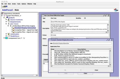
Figure 8 shows the corresponding identification of Use Cases and Scenarios in AUTORAID, with several represen-tative scenarios used to detail one Use Case. Furthermore, a single scenario is structured by identification of its steps.
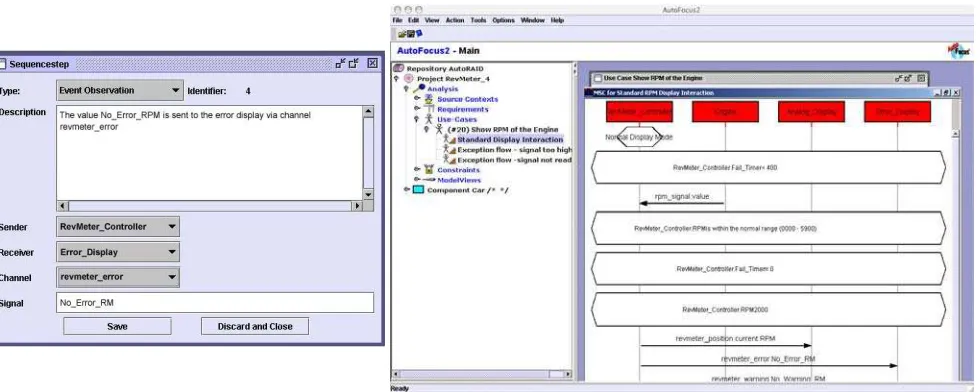
Then, every step of the previously informally described scenarios now can be analyzed and specified according to the system aspects of communication EventObservation4 (left-hand side of Fig. 9), application modes ModeObser-vation, and system/component statesStateObservation. As illustrated by anEventObservationof scenario-step 7, it al-lows the detailed specification of theSender andReceiver components, the communication Channels and theSignal data structure by selecting from an offered list. If the re-quired component is missing, it has to be constructed by theMotivationfunction before it can be selected within the EventObservation. With the options ModeObservationor StateObservation, the required conditions for the mode and state variables of an interaction step can be specified, re-spectively.
When the singleSequencestepmodels are defined using theObservationanalysis, the graphical view of the specified scenario can be generated by the Generate MSC-function (see right-hand side of Fig. 9). These scenario models can be used for further analysis or test case generation. Accord-ing to theMotivation-function, by generating the interaction model of a scenario step, a corresponding model element
4namedCommObeservationin the AUTORAID data model
EET Eventin AUTOFOCUSis created (see Fig. 5). Require-ments on these interaction events also can be mapped by the Association-function, and therefore structured and specified precisely.
3.3
Completion, Tracing, and Analysis
Major goal of the analysis is to revise requirements and system concepts in terms of product goals and cus-tomer needs, and to uncover inconsistencies and ambigui-ties within the specification. The core techniques of AU
-TORAID ensuring the developing an adequate specification of the system, are the constructive support for the refine-mentof a specification, the tracing of requirements, and a generic mechanism to analyzethe specification.
Through the constraints of the RE product model, AU
Figure 9. Scenario Analysis inAUTORAID
the benefit of requirements and design decisions can be an-alyzed, because AUTORAID provides a seamless modeling and coupling of requirements and system design. Based on goals and requirements system models and design concepts can be derived and constructed (forward tracing). On the other hand, system design concepts - and respectively solu-tion concepts - can and have to judged regarding its bene-fit, validated and integrated into the overall system design (backward tracing).
While the strictness of model-based formalization step implicitly helps to analyze a specification (e.g., when iden-tifying sender, receiver, and signal of a communication event), analysis techniques in form of consistency condi-tions can be applied to detected possible weaknesses of the model. Some of these consistency, or rather, soundness con-ditions used in the AUTORAID approach are:
• Each business requirement must be refined by at least
on application requirement.
• Each application requirement must be classified or
re-fined by a further application requirement.
• Each classified requirements must be formalized by a
element of the design level.
While the structuring, classification, and formalization steps are performed with user interaction, assisted by con-venient support for fast and efficient creation of sub-specifications, model-elements, etc., the consistency anal-ysis is performed automatically, presenting those specifica-tion and model elements that do not meet the consistency conditions.
4. Related Work
The basis of the AUTORAID approach is the elabora-tion, structuring, analysis, and validation and completion of requirements with the aid of basic functional models, as well as the consequent deduction of the requirements and system specification from goals (forward- and back-ward tracing). With the realization of this concepts within the tool AUTORAID and its integration into the mathemati-cally sound specification tool AUTOFOCUS, its possibilities
of verification can be used for validation and completion of the requirements.
Approaches of requirements structuring with the help of functional models can be found in the VORD approach [7], the KAOS approach [10] and in Leite’s and Freeman’s work onRequirements Validation Through Viewpoint Resolution (cf. [8]).
The root of VORD is the analysis and structuring of re-quirements in the view of features (services). The services of a system are described using scenarios. Non-functional requirements are mapped to these services. The services can be specified withevent tracesand state automata. The tool support of VORD allows to systematically recognizing con-flicts between requirements of different operational view-points (service specifications). A validation of the require-ments with the mapping to mathematically founded models and a tool supported verification is not provided by VORD so far.
mathematically founded information with the possibility of verification is not given here either.
Goal-oriented approaches like KAOS [10] analyze and elaborate requirements (goals) with aid of top-down and bottom-up solutions. Additionally, KAOS defines a methodological concept for refinement of goals and map-ping of the gained detailed requirements to software compo-nents (agents). Here, a concept for structuring requirements into functional (goals), non-functional requirements (soft-goals) and a further consideration of the requirements re-garding their relations (AND/OR-structures) are proposed. If the requirements regarding agents are derived, they can be specified precisely and verified with help of temporal logic. A stepwise elaboration and structuring of require-ments with the aid of functional models is not provided by KAOS. Here, a gap exists between the functional structur-ing and the detailed requirements regardstructur-ing agents.
In [4] a review-based approach for the stepwise structur-ing of textual requirements is proposed. This works with use-case descriptions structured using tables, and with state chart diagrams. AUTORAID simplifies this review process with the tool-based support of single transformation steps and provides methods for analysis, as well as the consider-ation of other aspects (e. g. data and structure).
In contrast to state-of-the-art RE tools like DOORS, Requiste Pro, or Caliber, which provide a generic prod-uct model consisting only of hierarchic and linked require-ments, AUTORAID uses a rich, domain-specific product model with specific concepts like scenarios, modes, or observations. Therefore, it effectively supports a multi-stakeholder, review-based RE process, improving the qual-ity of a requirements-specification in the early development steps as well as easing the transition to the design model.
5. Summary and Outlook
AUTORAID provides a model-based requirements anal-ysis by a reference model of RE work products (RE Prod-uct Model) and a strProd-uctured and stepwise transition from textual requirements to a design model. The goal-oriented Product Model provides a communication base for interdis-ciplinary consolidation of requirements and guides the it-erative refinement and completion to a problem-adequate system specifications. It contains a detailed conceptual model with different classes of requirements (e. g. business and application requirements, use cases, architectural con-straints,modal constraints) and tool-supported steps for in-tegrating requirements analysis and functional system de-sign. The final specified system behavior best meets the business, user and quality goals of the development. Ac-tual work extends the approach to a general model-based RE reference model that is tailorable to specific domain or project needs. Using a product model with extended, domain specific requirements and views (e. g. time
con-straints), a deep structuring and strong interconnection be-tween requirements and system model views gets possi-ble. Major goal is the assistance of complex analysis tech-niques (e. g. checking the consistency of system use scenar-ios and its state-based behavior specification or verifying the consistency of architectural interfaces constraints and functional system requirements), and the support of detailed generative steps like generating test cases from structured application scenarios.
References
[1] AUTOFOCUSHomepage, Documentation, Screenshots, Tu-torials, and Downloads. http://autofocus.in. tum.de.
[2] AUTORAID Homepage, Documentation, Screenshots,
and Downloads. http://wwwbroy.in.tum.de/
˜autoraid/.
[3] P. Braun, H. L¨otzbeyer, B. Sch¨atz, and O. Slotosch. Consis-tent Integration of Formal Methods. InProc. 6th Intl. Conf on Tools for the Analysis of Correct Systems (TACAS), LNCS 2280, 2000.
[4] C. Denger and B. Paech. An Integrated Quality Assurance Approach for Use Case Based Requirements. In B. Rumpe and W. Hesse, editors, Proceedings zur Tagung Model-lierung 2004, pages 307–308, Marburg, Germany, March, 24–26 2004.
[5] ITU. ITU-TS Recommendation Z.120: Message Sequence Chat (MSC). ITU-TS, Geneva 1996.
[6] G. Kontonya and I. Sommerville. Requirements Engineer-ing: Processes and Techniques. Wiley & Sons, 1998. [7] G. Kotonya and I. Sommerville. Requirements
Engineer-ing with Viewpoints. Technical report, Lancester University, 1995.
[8] L. Leite and P. Freeman. Requirements Validation Through Viewpoint Resolution.IEEE Transaction on Software Engi-neering, 1991.
[9] J. Phillips and O. Slotosch. The Quest for Correct Systems: Model Checking of Diagrams and Datatypes. InAsia Pacific Software Engineering Conference, 1999.