DESIGN, DEPLOYMENT
AND PERFORMANCE
DESIGN, DEPLOYMENT
AND PERFORMANCE
OF 4G-LTE NETWORKS
A PRACTICAL APPROACH
Ayman Elnashar
Emirates Integrated Telecomms Co., UAE
Mohamed A. El-saidny
QUALCOMM Technologies, Inc., USA
Mahmoud R. Sherif
Registered office
John Wiley & Sons Ltd, The Atrium, Southern Gate, Chichester, West Sussex, PO19 8SQ, United Kingdom For details of our global editorial offices, for customer services and for information about how to apply for permission to reuse the copyright material in this book please see our website at www.wiley.com.
The right of the author to be identified as the author of this work has been asserted in accordance with the Copyright, Designs and Patents Act 1988.
All rights reserved. No part of this publication may be reproduced, stored in a retrieval system, or transmitted, in any form or by any means, electronic, mechanical, photocopying, recording or otherwise, except as permitted by the UK Copyright, Designs and Patents Act 1988, without the prior permission of the publisher.
Wiley also publishes its books in a variety of electronic formats. Some content that appears in print may not be available in electronic books.
Designations used by companies to distinguish their products are often claimed as trademarks. All brand names and product names used in this book are trade names, service marks, trademarks or registered trademarks of their respective owners. The publisher is not associated with any product or vendor mentioned in this book.
Limit of Liability/Disclaimer of Warranty: While the publisher and author have used their best efforts in preparing this book, they make no representations or warranties with respect to the accuracy or completeness of the contents of this book and specifically disclaim any implied warranties of merchantability or fitness for a particular purpose. It is sold on the understanding that the publisher is not engaged in rendering professional services and neither the publisher nor the author shall be liable for damages arising herefrom. If professional advice or other expert assistance is required, the services of a competent professional should be sought.
Library of Congress Cataloging-in-Publication Data Elnashar, Ayman.
Design, deployment and performance of 4G-LTE networks : A Practical Approach / Dr Ayman Elnashar, Mr Mohamed A. El-saidny, Dr Mahmoud Sherif.
pages cm
Includes bibliographical references and index. ISBN 978-1-118-68321-7 (hardback)
1. Wireless communication systems. 2. Mobile communication systems. I. Title. TK5103.2.E48 2014
621.3845′6–dc23
2013037384 A catalogue record for this book is available from the British Library.
ISBN: 978-1-118-68321-7
Typeset in 10/12pt TimesLTStd by Laserwords Private Limited, Chennai, India
This book is dedicated to the memory of my father (God bless his soul) and also my mother, who’s been a rock of stability throughout my life. This book is also dedicated to my beloved wife whose consistent support and patience sustain me still.
My sincerest appreciations for a lifetime career that has surpassed anything my imagination could have conceived.
Ayman Elnashar
To my Family for all their continuous support. To my elder brother for his guidance and motivation throughout the years. To my inspirational, intelligent, and beautiful daughter, Hana.
Your work is going to fill a large part of your life, and the only way to be truly satisfied is to do what you believe is great work. And the only way to do great work is to love what you do. If you haven’t found it yet, keep looking. Don’t settle. As with all matters of the heart, you’ll know when you find it. – Steve Jobs Mohamed A. El-saidny
This work would not have been possible without the consistent and full support of my beloved family. To my beloved wife, Meram, to my intelligent, motivating, and beautiful kids, Moustafa, Tasneem, and Omar. You are my inspiration.
To my Dad, my Mom (God bless her soul), my brother, and my entire family. Thank you for all your support and encouragement.
There is no elevator to success. You have to take the stairs. – Unknown Author Those who think they have found this elevator will end up falling down the elevator shaft
Authors’ Biographies xv
Preface xvii
Acknowledgments xix
Abbreviations and Acronyms xxi
1 LTE Network Architecture and Protocols 1
Ayman Elnashar and Mohamed A. El-saidny
1.1 Evolution of 3GPP Standards 2
1.1.1 3GPP Release 99 3
1.1.2 3GPP Release 4 3
1.1.3 3GPP Release 5 3
1.1.4 3GPP Release 6 4
1.1.5 3GPP Release 7 4
1.1.6 3GPP Release 8 5
1.1.7 3GPP Release 9 and Beyond 5
1.2 Radio Interface Techniques in 3GPP Systems 6
1.2.1 Frequency Division Multiple Access (FDMA) 6
1.2.2 Time Division Multiple Access (TDMA) 6
1.2.3 Code Division Multiple Access (CDMA) 7
1.2.4 Orthogonal Frequency Division Multiple Access (OFDMA) 7
1.3 Radio Access Mode Operations 7
1.3.1 Frequency Division Duplex (FDD) 8
1.3.2 Time Division Duplex (TDD) 8
1.4 Spectrum Allocation in UMTS and LTE 8
1.5 LTE Network Architecture 10
1.5.1 Evolved Packet System (EPS) 10
1.5.2 Evolved Packet Core (EPC) 11
1.5.3 Evolved Universal Terrestrial Radio Access Network (E-UTRAN) 13
1.5.4 LTE User Equipment 13
1.6 EPS Interfaces 14
1.6.1 S1-MME Interface 14
1.6.2 LTE-Uu Interface 15
1.6.3 S1-U Interface 17
1.6.5 S4 (SGSN to SGW) 18
1.6.6 S5/S8 Interface 19
1.6.7 S6a (Diameter) 21
1.6.8 S6b Interface (Diameter) 21
1.6.9 S6d (Diameter) 22
1.6.10 S9 Interface (H-PCRF-VPCRF) 23
1.6.11 S10 Interface (MME-MME) 23
1.6.12 S11 Interface (MME–SGW) 23
1.6.13 S12 Interface 23
1.6.14 S13 Interface 24
1.6.15 SGs Interface 24
1.6.16 SGi Interface 25
1.6.17 Gx Interface 26
1.6.18 Gy and Gz Interfaces 27
1.6.19 DNS Interface 27
1.6.20 Gn/Gp Interface 27
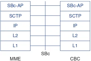
1.6.21 SBc Interface 28
1.6.22 Sv Interface 28
1.7 EPS Protocols and Planes 29
1.7.1 Access and Non-Access Stratum 29
1.7.2 Control Plane 29
1.7.3 User Plane 30
1.8 EPS Procedures Overview 31
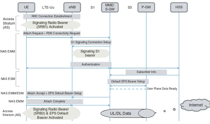
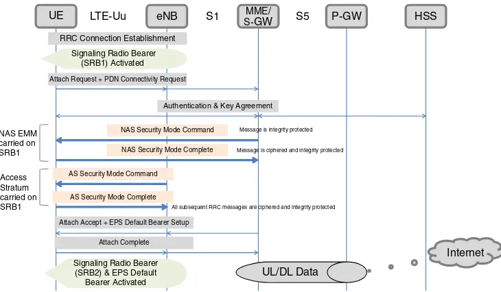
1.8.1 EPS Registration and Attach Procedures 31
1.8.2 EPS Quality of Service (QoS) 34
1.8.3 EPS Security Basics 36
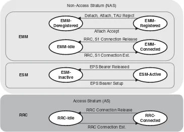
1.8.4 EPS Idle and Active States 38
1.8.5 EPS Network Topology for Mobility Procedures 39
1.8.6 EPS Identifiers 44
References 44
2 LTE Air Interface and Procedures 47
Mohamed A. El-saidny
2.1 LTE Protocol Stack 47
2.2 SDU and PDU 48
2.3 LTE Radio Resource Control (RRC) 50
2.4 LTE Packet Data Convergence Protocol Layer (PDCP) 52
2.4.1 PDCP Architecture 53
2.4.2 PDCP Data and Control SDUs 53
2.4.3 PDCP Header Compression 54
2.4.4 PDCP Ciphering 54
2.4.5 PDCP In-Order Delivery 54
2.4.6 PDCP in LTE versus HSPA 55
2.5 LTE Radio Link Control (RLC) 55
2.5.1 RLC Architecture 56
2.5.3 Control and Data PDUs 60
2.5.4 RLC in LTE versus HSPA 60
2.6 LTE Medium Access Control (MAC) 61
2.7 LTE Physical Layer (PHY) 61
2.7.1 HSPA(+) Channel Overview 61
2.7.2 General LTE Physical Channels 71
2.7.3 LTE Downlink Physical Channels 71
2.7.4 LTE Uplink Physical Channels 72
2.8 Channel Mapping of Protocol Layers 73
2.8.1 E-UTRAN Channel Mapping 73
2.8.2 UTRAN Channel Mapping 76
2.9 LTE Air Interface 76
2.9.1 LTE Frame Structure 76
2.9.2 LTE Frequency and Time Domains Structure 76
2.9.3 OFDM Downlink Transmission Example 80
2.9.4 Downlink Scheduling 81
2.9.5 Uplink Scheduling 88
2.9.6 LTE Hybrid Automatic Repeat Request (HARQ) 89
2.10 Data Flow Illustration Across the Protocol Layers 90
2.10.1 HSDPA Data Flow 90
2.10.2 LTE Data Flow 91
2.11 LTE Air Interface Procedures 92
2.11.1 Overview 92
2.11.2 Frequency Scan and Cell Identification 92
2.11.3 Reception of Master and System Information Blocks (MIB and SIB) 93
2.11.4 Random Access Procedures (RACH) 94
2.11.5 Attach and Registration 95
2.11.6 Downlink and Uplink Data Transfer 96
2.11.7 Connected Mode Mobility 96
2.11.8 Idle Mode Mobility and Paging 99
References 100
3 Analysis and Optimization of LTE System Performance 103 Mohamed A. El-saidny
3.1 Deployment Optimization Processes 104
3.1.1 Profiling Device and User Behavior in the Network 105
3.1.2 Network Deployment Optimization Processes 107
3.1.3 Measuring the Performance Targets 108
3.1.4 LTE Troubleshooting Guidelines 119
3.2 LTE Performance Analysis Based on Field Measurements 123 3.2.1 Performance Evaluation of Downlink Throughput 127
3.2.2 Performance Evaluation of Uplink Throughput 131
3.3 LTE Case Studies and Troubleshooting 134
3.3.1 Network Scheduler Implementations 135
3.3.4 LTE Handover Case Studies 146
3.4 LTE Inter-RAT Cell Reselection 153
3.4.1 Introduction to Cell Reselection 155
3.4.2 LTE to WCDMA Inter-RAT Cell Reselection 155
3.4.3 WCDMA to LTE Inter-RAT Cell Reselection 160
3.5 Inter-RAT Cell Reselection Optimization Considerations 165 3.5.1 SIB-19 Planning Strategy for UTRAN to E-UTRAN Cell Reselection 165 3.5.2 SIB-6 Planning Strategy for E-UTRAN to UTRAN Cell Reselection 167
3.5.3 Inter-RAT Case Studies from Field Test 168
3.5.4 Parameter Setting Trade-off 174
3.6 LTE to LTE Inter-frequency Cell Reselection 177
3.6.1 LTE Inter-Frequency Cell Reselection Rules 177
3.6.2 LTE Inter-Frequency Optimization Considerations 177
3.7 LTE Inter-RAT and Inter-frequency Handover 180
3.7.1 Inter-RAT and Inter-Frequency Handover Rules 187
3.7.2 Inter-RAT and Inter-Frequency Handover Optimization
Considerations 188
References 189
4 Performance Analysis and Optimization of LTE Key Features: C-DRX,
CSFB, and MIMO 191
Mohamed A. El-saidny and Ayman Elnashar
4.1 LTE Connected Mode Discontinuous Reception (C-DRX) 192
4.1.1 Concepts of DRX for Battery Saving 193
4.1.2 Optimizing C-DRX Performance 195
4.2 Circuit Switch Fallback (CSFB) for LTE Voice Calls 204
4.2.1 CSFB to UTRAN Call Flow and Signaling 206
4.2.2 CSFB to UTRAN Features and Roadmap 216
4.2.3 Optimizing CSFB to UTRAN 231
4.3 Multiple-Input, Multiple-Output (MIMO) Techniques 252
4.3.1 Introduction to MIMO Concepts 252
4.3.2 3GPP MIMO Evolution 256
4.3.3 MIMO in LTE 258
4.3.4 Closed-Loop MIMO (TM4) versus Open-Loop MIMO (TM3) 261
4.3.5 MIMO Optimization Case Study 267
References 270
5 Deployment Strategy of LTE Network 273
Ayman Elnashar
5.1 Summary and Objective 273
5.2 LTE Network Topology 273
5.3 Core Network Domain 276
5.3.1 Policy Charging and Charging (PCC) Entities 280
5.3.2 Mobility Management Entity (MME) 283
5.3.3 Serving Gateway (SGW) 286
5.3.5 Interworking with PDN (DHCP) 289
5.3.6 Usage of RADIUS on the Gi/SGi Interface 291
5.3.7 IPv6 EPC Transition Strategy 293
5.4 IPSec Gateway (IPSec GW) 294
5.4.1 IPSec GW Deployment Strategy and Redundancy Options 299
5.5 EPC Deployment and Evolution Strategy 300
5.6 Access Network Domain 303
5.6.1 E-UTRAN Overall Description 303
5.6.2 Home eNB 305
5.6.3 Relaying 307
5.6.4 End-to-End Routing of the eNB 308
5.6.5 Macro Sites Deployment Strategy 312
5.6.6 IBS Deployment Strategy 317
5.6.7 Passive Inter Modulation (PIM) 319
5.7 Spectrum Options and Guard Band 327
5.7.1 Guard Band Requirement 327
5.7.2 Spectrum Options for LTE 327
5.8 LTE Business Case and Financial Analysis 333
5.8.1 Key Financial KPIs [31] 334
5.9 Case Study: Inter-Operator Deployment Scenario 341
References 347
6 Coverage and Capacity Planning of 4G Networks 349 Ayman Elnashar
6.1 Summary and Objectives 349
6.2 LTE Network Planning and Rollout Phases 349
6.3 LTE System Foundation 351
6.3.1 LTE FDD Frame Structure 351
6.3.2 Slot Structure and Physical Resources 353
6.3.3 Reference Signal Structure 356
6.4 PCI and TA Planning 360
6.4.1 PCI Planning Introduction 360
6.4.2 PCI Planning Guidelines 361
6.4.3 Tracking Areas (TA) Planning 362
6.5 PRACH Planning 370
6.5.1 Zadoff-Chu Sequence 371
6.5.2 PRACH Planning Procedures 372
6.5.3 Practical PRACH Planning Scenarios 373
6.6 Coverage Planning 375
6.6.1 RSSI, RSRP, RSRQ, and SINR 375
6.6.2 The Channel Quality Indicator 378
6.6.3 Modulation and Coding Scheme and Link Adaptation 381
6.6.4 LTE Link Budget and Coverage Analysis 385
6.6.5 Comparative Analysis with HSPA+ 401
6.6.6 Link Budget for LTE Channels 405
6.7 LTE Throughput and Capacity Analysis 418
6.7.1 Served Physical Layer Throughput Calculation 418
6.7.2 Average Spectrum Efficiency Estimation 418
6.7.3 Average Sector Capacity 419
6.7.4 Capacity Dimensioning Process 419
6.7.5 Capacity Dimensioning Exercises 423
6.7.6 Calculation of VoIP Capacity in LTE 426
6.7.7 LTE Channels Planning 431
6.8 Case Study: LTE FDD versus LTE TDD 437
References 443
7 Voice Evolution in 4G Networks 445
Mahmoud R. Sherif
7.1 Voice over IP Basics 445
7.1.1 VoIP Protocol Stack 445
7.1.2 VoIP Signaling (Call Setup) 449
7.1.3 VoIP Bearer Traffic (Encoded Speech) 449
7.2 Voice Options for LTE 451
7.2.1 SRVCC and CSFB 451
7.2.2 Circuit Switched Fallback (CSFB) 452
7.3 IMS Single Radio Voice Call Continuity (SRVCC) 455
7.3.1 IMS Overview 456
7.3.2 VoLTE Call Flow and Interaction with IMS 460
7.3.3 Voice Call Continuity Overview 469
7.3.4 SRVCC from VoLTE to 3G/2G 471
7.3.5 Enhanced SRVCC (eSRVCC) 480
7.4 Key VoLTE Features 482
7.4.1 End-to-End QoS Support 482
7.4.2 Semi-Persistent Scheduler 486
7.4.3 TTI Bundling 488
7.4.4 Connected Mode DRX 491
7.4.5 Robust Header Compression (ROHC) 492
7.4.6 VoLTE Vocoders and De-Jitter Buffer 497
7.5 Deployment Considerations for VoLTE 503
References 505
8 4G Advanced Features and Roadmap Evolutions from LTE to LTE-A 507 Ayman Elnashar and Mohamed A. El-saidny
8.1 Performance Comparison between LTE’s UE Category 3 and 4 509
8.1.1 Trial Overview 512
8.1.2 Downlink Performance Comparison in Near and Far Cell Conditions 513 8.1.3 Downlink Performance Comparison in Mobility Conditions 515
8.2 Carrier Aggregation 516
8.2.1 Basic Definitions of LTE Carrier Aggregation 518
8.2.2 Band Types of LTE Carrier Aggregation 519
8.3 Enhanced MIMO 520
8.3.1 Enhanced Downlink MIMO 522
8.3.2 Uplink MIMO 523
8.4 Heterogeneous Network (HetNet) and Small Cells 523 8.4.1 Wireless Backhauling Applicable to HetNet Deployment 524
8.4.2 Key Features for HetNet Deployment 528
8.5 Inter-Cell Interference Coordination (ICIC) 529
8.6 Coordinated Multi-Point Transmission and Reception 531
8.6.1 DL CoMP Categories 531
8.6.2 UL CoMP Categories 533
8.6.3 Performance Evaluation of CoMP 533
8.7 Self-Organizing, Self-Optimizing Networks (SON) 535
8.7.1 Automatic Neighbor Relation (ANR) 536
8.7.2 Mobility Robust Optimization (MRO) 537
8.7.3 Mobility Load Balancing (MLB) 539
8.7.4 SON Enhancements in LTE-A 540
8.8 LTE-A Relays and Home eNodeBs (HeNB) 540
8.9 UE Positioning and Location-Based Services in LTE 541
8.9.1 LBS Overview 541
8.9.2 LTE Positioning Architecture 543
References 544
Ayman Elnashar was born in Egypt in 1972. He received the B.S. degree in electrical engineering from Alexandria University, Alexandria, Egypt, in 1995 and the M.Sc. and Ph.D. degrees in electrical communications engineering from Mansoura University, Mansoura, Egypt, in 1999 and 2005, respectively. He obtained his M.Sc. and Ph.D. degrees while work-ing fulltime. He has more than 17 years of experience in telecoms industry includwork-ing GSM, GPRS/EDGE, UMTS/HSPA+/LTE, WiMax, WiFi, and transport/backhauling technologies. He was part of three major start-up telecom operators in MENA region (Mobinil/Egypt, Mobily/KSA, and du/UAE) and held key leadership positions. Currently, he is Sr. Director of Wireless Broadband, Terminals, and Performance with the Emirates Integrated Telecommuni-cations Co. “du”, UAE. He is in charge of mobile and fixed wireless broadband networks. He is responsible for strategy and innovation, design and planning, performance and optimization, and rollout/implementation of mobile and wireless broadband networks. He is the founder of the Terminals department and also the terminals lab for end-to-end testing, validation, and benchmarking of mobile terminals. He managed and directed the evolution, evaluation, and introduction of du mobile broadband HSPA+/LTE networks. Prior to this, he was with Mobily, Saudi Arabia, from June 2005 to Jan 2008 and with Mobinil (orange), Egypt, from March 2000 to June 2005. He played key role in contributing to the success of the mobile broadband network of Mobily/KSA.
He managed several large-scale networks, and mega projects with more than 1.5 billion USD budgets including start-ups (LTE 1800 MHz, UMTS, HSPA+, and WiMAX16e), networks expansions (GSM, UMTS/HSPA+, WiFi, and transport/backhauling) and swap projects (GSM, UMTS, MW, and transport network) from major infrastructure vendors. He obtained his PhD degree in multiuser interference cancellation and smart antennas for cellular systems. He published 20+papers in wireless communications arena in highly ranked journals such as IEEE Transactions on Antenna and Propagation, IEEE Transactions Vehicular technology, and IEEE Transactions Circuits and Systems I, IEEE Vehicular technology Magazine, IET Signal Processing, and international conferences. His research interests include practical performance analysis of cellular systems (CDMA-based & OFDM-based), 3G/4G mobile networks planning, design, and Optimization, digital signal processing for wireless com-munications, multiuser detection, smart antennas, MIMO, and robust adaptive detection and beamforming. He is currently working on LTE-Advanced and beyond including eICIC, HetNet, UL/DL CoMP, 3D Beamforming, Combined LTE/HSPA+, Combined LTE/WiFi: simultaneous reception, etc…
degree in Electrical Engineering from the University of Alabama in Huntsville, USA in 2002 and 2004, respectively. From 2004 to 2008, he worked in Qualcomm CDMA Technology, Inc. (QCT), San Diego, California, USA. He was responsible for performance evaluation and analysis of the Qualcomm UMTS system and software solutions used in user equipment. As part of his assignments, he developed and implemented system studies to optimize the perfor-mance of various UMTS algorithms. The enhancements utilize Cell re-selection, Handover, Cell Search and Paging. He worked on several IOT and field trials to evaluate and improve the performance of 3G systems. Since 2008, he has been working in Qualcomm Corporate Engineering Services division in Dubai, UAE. He has been working on expanding the 3G/4G technologies footprints with operators, with an additional focus on user equipment and net-work performance as well as technical roadmaps related to the industry. Mohamed is currently supporting operators in Middle East and North Africa in addition to worldwide network oper-ators and groups in LTE commercial efforts. His responsibilities are to ensure the device and network performance are within expectations. He led a key role in different first time features evaluations such as CSFB, C-DRX, IRAT, and load balance techniques in LTE. As part of this role, he is focused on aligning network operators to the device and chipset roadmaps and products in both 3G and 4G. Mohamed is the author of several international IEEE journal papers and contributions to 3GPP, and an inventor of numerous patents.
Cellular mobile networks have been evolving for many years. Several cellular systems and networks have been developed and deployed worldwide to provide the end user with quality and reliable communication over the air. Mobile technologies from the first to third generation have been quickly evolving to meet the need of services for voice, video, and data.
Today, the transition to smartphones has steered the user’s interest toward a more mobile-based range of applications and services, increasing the demand for more network capacity and bandwidth. Meanwhile, this transition presents a significant revenue opportunity for network operators and service providers, as there is substantially higher average revenue per user (ARPU) from smartphone sales and relevant services. While the rollout of more advanced radio networks is proceeding rapidly, smartphone penetration is also increasing exponentially. Therefore, network operators need to ensure that the subscribers’ experience stays the same as, or is even better than, with the older existing systems.
With the growing demand for data services, it is becoming increasingly challenging to meet the required data capacity and cell-edge spectrum efficiency. This adds more demand on the network operators, vendors and device providers to apply methods and features that stabilize the system’s capacity and consequently improves the end-user experience. 4G systems and relevant advanced features have the capabilities to keep up with today’s widespread use of mobile-communication devices, providing a range of mobile services and quality communications.
This book describes the long term evolution (LTE) technology for mobile systems; a transi-tion from third to fourth generatransi-tion. LTE has been developed in the 3GPP (Third Generatransi-tion Partnership Project), starting from the first version in Release 8 and through to the contin-uing evolution to Release 10, the latest version of LTE, also known as LTE-Advanced. The analysis in this book is based on the LTE of 3GPP Release 8 together with Release 9 and Release 10 roadmaps, with a focus on the LTE-FDD (frequency division duplex) mode . Unlike other books, the authors have bridged the gap between theory and practice, thanks to hands on experience in the design, deployment, and performance of commercial 4G-LTE networks and terminals.
Chapters 1 and 2 describe the LTE system architecture, interfaces, and protocols. They also introduce the LTE air interface and layers, in addition to downlink and uplink channels and procedures.
16-QAM 16-Quadrature amplitude modulation 64-QAM 64-Quadrature amplitude modulation 1G, 2G, 3G or 4G 1st, 2nd, 3rd, 4th generation
3GPP Third generation partnership project 3GPP2 Third generation partnership project 2 AAA Authentication, authorization and accounting
ACK Acknowledgment
AES Advanced encryption standard
AF Application Function
AIPN All-IP network
AMBR Aggregate maximum bit rate AMC Adaptive modulation and coding AMD Acknowledged mode data
AN Access network
APN Access point name
ARP Allocation and retention priority ARQ Automatic repeat request
AS Access stratum
BC Business Case
BCCH Broadcast control channel
BCH Broadcast channel
BI Backoff indicator
BLER Block error rate
BP Bandwidth part
BSR Buffer status report
BW Bandwidth
CDS Channel dependent scheduling CFI Control format indicator
CN Core network
COGS Cost of Goods Sold
CP Control plane
Cyclic prefix
CQI Channel quality indicator CRC Cyclic redundancy check CRF Charging Rules Function
C-RNTI Cell radio network temporary identifier
CS Circuit switched
CSG Closed subscriber group CSI Channel signal information
CW Code word
DAS Distributed Antenna System DCCH Dedicated control channel DCI Downlink control information DFT Discrete Fourier transform
DFTS-OFDM Discrete Fourier transform spread orthogonal frequency division multi-plexing
DL Downlink
DL-SCH Downlink shared channel
DM Demodulation
DM-RS Demodulation reference signal
DNS Domain Name System
DRX Discontinuous transmission
DS Data services
DTCH Dedicated traffic channel
E-AGCH Enhanced absolute granting channel
EBITDA Earnings Before Interest, Taxes, Depreciation, and Amortization E-DCH Enhanced dedicated channel
E-DPCCH Enhanced dedicated physical control channel E-DPDCH Enhanced dedicated physical data channel E-HICH Enhanced hybrid indicator channel EEA EPS encryption algorithm
EIA EPS integrity algorithm EIR Equipment Identity register EMM EPS mobility management
eNB Evolved node B
EPC Evolved packet core
EPLMN Equivalent PLMN
EPRE Energy per resource element EPS Evolved packet system
E-RGCH Enhanced relative granting channel ESM EPS session management
ETWS Earthquake and tsunami warning system
E-UTRA Evolved UMTS terrestrial radio access; PHY aspects
E-UTRAN Evolved UMTS terrestrial radio access network; MAC/L2/L3 aspects
FD Full-duplex
FDD Frequency division duplex FDM Frequency division multiplexing FDMA Frequency division multiple access FFT Fast Fourier transform
FH Frequency hopping
FI Framing information
FL Forward link
FMS First missing sequence
FS Frame structure
FSTD Frequency shift time diversity GBR Guaranteed bit rate
GERAN GSM/EDGE radio access network GGSN GPRS gateway support node GPRS General packet radio service
GSM Global system for mobiles (European standard) GTP-U GPRS tunneling protocol – user
GUMMEI Globally unique MME identity GUTI Globally unique temporary identifier
GW Gateway
HA Home agent
HAP ID HARQ process ID
HARQ Hybrid ARQ
HD Half-duplex
HFN Hyper frame number
HI Hybrid ARQ indicator
HLD High Level Design
HLR Home location register
HNBID Home evolved node B identifier
HO Handover
HPLMN Home public land mobile network HRPD High rate packet data
HS High speed
HSDPA High speed downlink packet access HS-DPCCH High speed dedicated control channel HSPA High speed packet access
HSPA+ High speed packet access evolved or enhanced HSS Home subscriber service
IMSI International Mobile Subscriber Identity
IP Internet protocol
IP-CAN IP connectivity access network ISI Inter-symbol interference ISR Idle signaling load reduction IRR Internal Rate of Return L1, L2, L3 Layer 1, 2, 3
LA Location area
LAC Location area code
LAI Location area identifier LAU Location area updating LCG Logical channel group LDAP Lightweight Directory Access
LFDM Localized frequency division multiplexing
LI Lawful Interception
LI Length indicators
LTE Long term evolution LTI Linear time invariant MAC Medium access control
MAC-I Message authentication code for integrity MBMS Multimedia broadcast multicast service
MBR Maximum bit rate
MBSFN Multimedia broadcast over a single frequency network MCCH Multicast control channel
MCH Multicast channel
MCS Modulation and coding schemes
MCW Multiple code word
ME Mobile equipment
MIB Master information block MIMO Multiple-input–multiple-output MME Mobility management entity
MMEC MME code
MMEGI MME group ID
MSISDN Mobile Subscriber Integrated Services Digital Network-Number
MOS Mean Opinion Score
MTCH Multicast traffic channel
MU-MIMO Multi-user multiple-input–multiple-output NAK Negative acknowledgment
NAS Non-access stratum
NDI New data indicator
NID Network ID
NPV Net Present Value
OCS Online Charging System OFCS Offline Charging System
OS Operating system
PAPR Peak-to-average power ratio
PAR Peak to average ratio
PBCH Physical broadcast channel PCC Policy charging and control PCCH Paging control channel
PCFICH Physical control format indicator channel
PCH Paging channel
PCRF Policy and charging rules function PDCCH Physical downlink control channel PDCP Packet data convergence protocol
PDG Packet data gateway
PDN Packet data network
PDSCH Physical downlink shared channel PDSN Packet data serving node
PDU Protocol data unit
PELR Packet error loss rate P-GW Packet data network gateway
PHICH Physical hybrid automatic repeat request indicator channel
PHR Power headroom report
PHY Physical layer
PIM Passive Intermodulation
PLMN Public land mobile network PMCH Physical multicast channel PMI Precoding matrix indicator
PMIP Proxy mobile IP
PoC Push-to-talk over cellular PRACH Physical random access channel
PRB Physical resource block
PS Packet switched
PSC Primary synchronization code P-SCH Primary synchronization channel PSS Primary synchronization signal PSTN Packet switched telephone network PSVT Packet switched video telephony
PTT Push-to-talk
PUCCH Physical uplink control channel PUSCH Physical uplink shared channel QAM Quadrature amplitude modulation
QCI QoS class identifier
QoS Quality of service
QPSK Quadrature phase shift keying
RA Routing area
RAC Routing area code
RACH Random access channel
RAPID Random access preamble identifier
RAR Random access response
RAU Routing area updating
RB Resource block
RBG Resource block group
RDS RMS delay spread
RE Resource element
REG Resource element group
RI Rank indicator
RIV Resource indication value
RL Reverse link
RLC Radio link control
RLF Radio link failure
RMS Root-mean-square
RN Relay Node
RNC Radio network controller
RNL Radio network layer
RNTI Radio network temporary identifier ROHC Robust header compression
ROI Return On Investment
RPLMN Registered PLMN
RRC Radio resource control
RRM Radio resource management
RS Reference signal
RV Redundancy version
SAE System architecture evolution
SAW Stop-and-wait
SC-FDM Single-carrier frequency division multiplexing SC-FDMA Single-carrier frequency division multiple access
SCH Supplemental channel (CDMA2000)
Synchronization channel (WCDMA) SCTP Stream control transmission protocol
SCW Single code word
SDF Service data low
SDM Spatial division multiplexing SDMA Spatial division multiple access
SDU Service data unit
SFBC Space frequency block code
SFN System frame number
SGSN Serving GPRS support node
S-GW Serving gateway
SI System information message
SIB System information block
SINR Signal to interference noise ratio
SM Session management
SNR Signal to noise ratio
SOAP Simple Object Access Protocol SPOF Single Point of Failure
SPS Semi-persistent scheduling
SR Scheduling request
SRS Sounding reference signals SSC Secondary synchronization code S-SCH Secondary synchronization channel SSS Secondary synchronization signal
SU-MIMO Single-user multiple-input–multiple-output
TA Tracking area
Timing advance/alignment
TAC Tracking area code
TAI (_List) Tracking area identifier (_List)
TAU Tracking area update
TDD Time division duplex
TDM Time division multiplexing TDMA Time division multiple access
TFT Traffic flow template
TPC Transmit power control
TTI Transmission time interval
Tx Transmit
UCI Uplink control information
UE User equipment
UL Uplink
UL-SCH Uplink shared channel
UMTS Universal mobile telecommunications system
UP User plane
UTRA UMTS terrestrial radio access
UTRAN UMTS terrestrial radio access network
VAF Voice Activity Factor
VoIP Voice over Internet protocol
VoLTE Voice over LTE
VRB Virtual resource block
VT Video telephony
WACC Weighted Average Cost of Capital WCDMA Wideband code division multiple access
WiMAX Worldwide interoperability for microwave access
X2 The interface between eNodeBs
1
LTE Network Architecture and
Protocols
Ayman Elnashar and Mohamed A. El-saidny
Cellular mobile networks have been evolving for many years. The initial networks are referred to as First Generation, or 1G systems. The 1G mobile system was designed to utilize analog. It included the AMPS (advanced mobile phone system). The Second Generation, 2G mobile systems, were introduced utilizing digital multiple access technology; TDMA (time division multiple access) and CDMA (code division multiple access). The main 2G networks were GSM (global system for mobile communications) and CDMA, also known as cdmaOne or IS-95 (Interim Standard 95). The GSM system still has worldwide support and is available for deployment on several frequency bands, such as 900, 1800, 850, and 1900 MHz. CDMA systems in 2G networks use a spread spectrum technique and utilize a mixture of codes and timing to identify cells and channels. In addition to being digital, as well as improving capacity and security, the 2G systems also offer enhanced services, such as SMS (short message service) and circuit switched (CS) data. Different variations of the 2G technology evolved later to extend the support of efficient packet data services, and to increase the data rates. GPRS (general packet radio system) and EDGE (enhanced data rates for global evolution) systems have been the evolution path of GSM. The theoretical data rate of 473.6 kbps enabled the operators to offer multimedia services efficiently. Since it does not comply with all the features of a 3G system, EDGE is usually categorized as 2.75G.
3G (Third Generation) systems are defined by IMT2000 (International Mobile Telecom-munications). IMT2000 defines that a 3G system should provide higher transmission rates in the range of 2 Mbps for stationary use and 348 kbps in mobile conditions. The main 3G technologies are:
• WCDMA (wideband code division multiple access)– This was developed by the 3GPP (Third Generation Partnership Project). WCDMA is the air interface of the 3G UMTS (uni-versal mobile telecommunications system). The UMTS system has been deployed based on
Design, Deployment and Performance of 4G-LTE Networks: A Practical Approach, First Edition. Ayman Elnashar, Mohamed A. El-saidny and Mahmoud R. Sherif.
the existing GSM communication core network (CN) but with a totally new radio access technology (RAT) in the form of WCDMA. Its radio access is based on FDD (frequency division duplex). Current deployments are mainly at 2.1 GHz bands. Deployments at lower frequencies are also possible, such as UMTS900. UMTS supports voice and multimedia services.
• TD-CDMA (time division multiple access)– This is typically referred to as UMTS TDD (time division duplex) and is part of the UMTS specifications. The system utilizes a com-bination of CDMA and TDMA to enable efficient allocation of resources.
• TD-SCDMA (time division synchronous code division multiple access)– This has links to the UMTS specifications and is often identified as UMTS-TDD low chip rate. Like TD-CDMA, it is also best suited to low mobility scenarios in microcells or picocells. • CDMA2000– This is a multi-carrier technology standard which uses CDMA. It is part of
the 3GPP2 standardization body. CDMA2000 is a set of standards including CDMA2000 EV-DO (evolution-data optimized) which has various revisions. It is backward compatible with cdmaOne.
• WiMAX (worldwide interoperability for microwave access)– This is another wireless technology which satisfies IMT2000 3G requirements. The air interface is part of the IEEE (Institute of Electrical and Electronics Engineers) 802.16 standard which originally defined PTP (point-to-point) and PTM (point-to-multipoint) systems. This was later enhanced to provide greater mobility. WiMAX Forum is the organization formed to promote interoper-ability between vendors.
4G (Fourth Generation) cellular wireless systems have been introduced as the latest version of mobile technologies. 4G is defined to meet the requirements set by the ITU (International Telecommunication Union) as part of IMT Advanced.
The main drivers for the network architecture evolution in 4G systems are: all-IP (Internet protocol) -based, reduced network cost, reduced data latencies and signaling load, interwork-ing mobility among other access networks in 3GPP and non-3GPP, always-on user experience with flexible quality of service (QoS) support, and worldwide roaming capability. 4G systems include different access technologies:
• LTE and LTE-Advanced (long term evolution)– This is part of 3GPP. LTE as it stands now does not meet all IMT Advanced features. However, LTE-Advanced is part of a later 3GPP release and has been designed specifically to meet 4G requirements.
• WiMAX 802.16m– The IEEE and the WiMAX Forum have identified 802.16m as their offering for a 4G system.
• UMB (ultra mobile broadband)– This is identified as EV-DO Rev C. It is part of 3GPP2. Most vendors and network operators have decided to promote LTE instead.
1.1
Evolution of 3GPP Standards
The availability of devices on a more advanced 3GPP release makes a great contribution to the choice of evolution by the operator. Collaboration between network operators, network vendors, and chipset providers is an important step in defining the roadmap and evolution of 3GPP features and releases. This has been the case in many markets.
1.1.1
3GPP Release 99
3GPP Release 99 has introduced UMTS, as well as the EDGE enhancement to GPRS. UMTS contains all features needed to meet the IMT-2000 requirements as defined by the ITU. It is able to support CS voice and video services, as well as PS (packet switched) data services over common and dedicated channels. The theoretical data rate of UMTS in this release is 2 Mbps. The practical uplink and downlink data rates for UMTS in deployed networks have been 64, 128, and 384 kbps.
1.1.2
3GPP Release 4
Release 4 includes enhancements to the CN. The concept of all-IP networks has been intro-duced in this release. There has not been any significant change added to the user equipment (UE) or air interface in this release.
1.1.3
3GPP Release 5
Release 5 is the first major addition to the UMTS air interface. It adds HSDPA (high speed downlink packet access) to improve capacity and spectral efficiency. The goal of HSDPA in the 3GPP roadmap was to improve the end-user experience and to keep up with the evolution taking place in non-3GPP technologies. During the time when HSDPA was being developed, the increasing interest in mobile-based services demanded a significant improvement in the air interface of the UMTS system.
HSDPA improves the downlink speeds from 384 kbps to a maximum theoretical 14.4 Mbps. The typical rates in the Release 5 networks and devices are 3.6 and 7.2 Mbps. The uplink in Release 5 has preserved the capabilities of Release 99.
HSDPA provides the following main features which hold as the fundamentals of all subse-quent 3GPP evolutions:
• Adaptive modulation– In addition to the original UMTS modulation scheme, QPSK (quadrature phase shift keying), Release 5 also includes support for 16-QAM (quadrature amplitude modulation).
• Flexible coding– Based on fast feedback from the mobile in the form of a CQI (chan-nel quality indicator), the UMTS base station (known as NodeB) is able to modify the effective coding rate and thus increase system efficiency. In Release 99, such adaptive data rate scheduling took place at the RNC (radio network controller) which impacted the cell capacity and edge of cell data rates.
• HARQ (hybrid automatic repeat request)– If a packet does not get through to the UE successfully, the system employs HARQ. This improves the retransmission timing, thus requiring less reliance on the RNC. In Release 99, the packet re-transmission was mainly controlled by the physical (PHY) layer as well as the RNC’s ARQ (automatic repeat request) algorithm, which was slower in adapting to the radio conditions.
1.1.4
3GPP Release 6
Release 6 adds various features, with HSUPA (high speed uplink packet data) being the key one. HSUPA also goes under the term “enhanced uplink, EUL”. The term HSPA (high speed packet access) is normally used to describe a Release 6 network since an HSUPA call requires HSDPA on the downlink.
The downlink of Release 6 remained the same as in HSDPA of Release 5. The uplink data rate of the HSUPA system can go up to 5.76 Mbps with 2 ms TTI used in the network and devices. The practical uplink data rates deployed are 1.4 and 2 Mbps. It is worth noting that there is a dependence between the downlink and uplink data rates. Even if the user is only downloading data at a high speed, the uplink needs to cope with the packet acknowledgments at the same high speed. Therefore any data rate evolution in the downlink needs to have an evolved uplink as well.
HSUPA, like HSDPA, adds functionalities to improve packet data which include:
• Flexible coding– HSUPA has the ability to dynamically change the coding and therefore improves the efficiency of the system.
• Fast power scheduling– A key fact of HSUPA is that it provides a method to schedule the power to different mobiles. This scheduling can use either a 2 or 10 ms TTI. 2 ms usually reveals a challenge on the uplink interference and coverage when compared to 10 ms TTI operation. Hence, a switch between the two TTI is possible within the same EUL data call. • HARQ– Like HSDPA, HSUPA also utilizes HARQ concepts in lower layers. The main difference is the timing relationship for the retransmission and the synchronized HARQ processes.
1.1.5
3GPP Release 7
The main addition to this release is HSPA+, also known as evolved HSPA. During the commer-cialization of HSPA, LTE system development has been started, promising a more enhanced bandwidth and system capacity. Evolution of the HSPA system was important to keep up with any competitor technologies and prolong the lifetime of UMTS systems.
HSPA+provides various enhancements to improve PS data delivery. The features in HSPA+ have been introduced as add-ons. The operators typically evaluate the best options of HSPA+ features for deployment interests, based on the traffic increase requirements, flexibility, and the cost associated for the return of investment. HSPA+in Release 7 includes:
• 64 QAM– This is added to the downlink and enables HSPA+to operate at a theoretical rate of 21.6 Mbps.
• MIMO (multiple input multiple output) operation– This offers various capacity benefits including the ability to reach a theoretical 28.8 Mbps data rate in the downlink.
• Power and battery enhancements– Various enhancements such as CPC (continuous packet connectivity) have been included. CPC enables DTX (discontinuous transmission) and DRX (discontinuous reception) functions in connected mode.
• Less data packet overhead– The downlink includes an enhancement to the lower layers in the protocol stack. This effectively means that fewer headers are required, and in turn, improves the system efficiency.
1.1.6
3GPP Release 8
On the HSPA+side, Release 8 has continued to improve the system efficiency and data rates by providing:
• MIMO with 64 QAM modulation– It enables the combination of 64 QAM and MIMO, thus reaching a theoretical rate of 42 Mbps, that is, 2×21.6 Mbps.
• Dual cell operation– DC-HSDPA (dual cell high speed downlink packet access) is a fea-ture which is further enhanced in Releases 9 and 10. It enables a mobile to effectively utilize two 5 MHz UMTS carriers. Assuming both are using 64 QAM (21.6 Mbps), the theoreti-cal data rate is 42 Mbps. DC-HSDPA has gained the primary interest over other Release 8 features, and most networks are currently either supporting it or in the deployment stage. • Further power and battery enhancements– deploys a feature known as enhanced fast
dormancy as well as enhanced RRC state transitions.
The 3GPP Release 8 defines the first standardization of the LTE specifications. The evolved packet system (EPS) is defined, mandating the key features and components of both the radio access network (E-UTRAN, evolved universal terrestrial radio access network) and the CN (evolved packet core, EPC). Orthogonal frequency division multiplexing is defined as the air interface with the ability to support multi-layer data streams using MIMO antenna systems to increase spectral efficiency.
LTE is defined as an all-IP network topology differentiated over the legacy CS domain. However, the Release 8 specification makes use of the CS domain to maintain compatibility with the 2G and 3G systems utilizing the voice calls circuit switch Fallback (CSFB) technique for any of those systems.
LTE in Release 8 has a theoretical data rate of 300 Mbps. The most common deployment is 100 to 150 Mbps with a full usage of the bandwidth, 20 MHz. Several other variants are also deployed in less bandwidth and hence with lower data rates. The bandwidth allocation is tied to the amount of spectrum acquired by the LTE network operators in every country.
The motivations and different options discussed in 3GPP for the EPS network architecture have been detailed in several standardized technical reports in [1–4].
1.1.7
3GPP Release 9 and Beyond
On the HSPA+ side, Release 9 and beyond continued to build on the top of previous HSPA+enhancements by introducing DC-HSUPA, MIMO+DC-HSDPA, and multi-carrier high speed downlink packet access (MC-HSDPA). The downlink of HSPA+in this release is expected to reach 84 Mbps, while the uplink can reach up to 42 Mbps.
Release 10 includes the standardization of LTE Advanced, the 3GPP’s 4G offering. It includes modification to the LTE system to facilitate 4G services. The requirements of ITU are to develop a system with increased data rates up to 1 Gbps in the downlink and 500 Mbps in the uplink. Other requirements of ITU’s 4G are worldwide roaming and compatibility of services. LTE-Advanced is now seeing more interest, especially from the operators who have already deployed LTE in early stages.
As discussed in this 3GPP evolution, the 4G system is designed to refer to LTE-Advanced. However, since UMTS has been widely used as a 3G system, investing in and building up an ecosystem for an LTE network using the same “3G” term would have been misinterpreted. Hence, regulators in most countries have allowed the mobile operators to use the term “4G” when referring to LTE. This book considers the term 4G when referring to an LTE system, especially for the concepts that are still common between LTE and LTE-Advanced.
This chapter describes the overall architecture of an LTE CN, radio access protocols, and air interface procedures. This chapter and the upcoming parts of the book focus on Release 8 and 9 of the 3GPP specifications. The last chapter of the book gives an overview of the features beyond Release 9.
1.2
Radio Interface Techniques in 3GPP Systems
In wireless cellular systems, mobile users share a common medium for transmission. There are various categories of assignment. The main four are FDMA (frequency division multiple access), TDMA, CDMA, and OFDMA (orthogonal frequency division multiple access). Each of the technologies discussed earlier in the chapter utilizes one of these techniques. This is another reason for distinguishing the technologies.
1.2.1
Frequency Division Multiple Access (FDMA)
In order to accommodate various devices on the same wireless network, FDMA divides the available spectrum into sub-bands or channels. Using this technique, a dedicated channel can be allocated to a user, while other users occupy other channels or frequencies.
FDMA channels can suffer from higher interference. They cannot be close together due to the energy from one transmission affecting the adjacent or neighboring channels. To combat this, additional guard bands between channels are required, which also reduces the system’s spectral efficiency. The uplink or downlink receiver must use filtering to mitigate interference from other users.
1.2.2
Time Division Multiple Access (TDMA)
frequency and time. The number of timeslots in a TDMA frame is dependent on the system. For example, GSM utilizes eight timeslots.
TDMA systems are digital and therefore offer security features such as ciphering and integrity. In addition, they can employ enhanced error detection and correction schemes including FEC (forward error correction). This enables the system to be more resilient to noise and interference and therefore they have a greater spectral efficiency than FDMA systems.
1.2.3
Code Division Multiple Access (CDMA)
The concept of CDMA is slightly different to that of FDMA and TDMA. Instead of sharing resources in the time or frequency domain, the devices are able to use the system at the same time and using the same frequency. This is possible because each transmission is separated using a unique channelization code.
UMTS, cdmaOne, and CDMA2000 all use CDMA as their air interface technique. However, the implementation of the codes and the bandwidths used by each technology is different. For example, UMTS utilizes a 5 MHz channel bandwidth, whereas cdmaOne uses only 1.25 MHz. Codes are used to achieve orthogonality between the users. In the HSDPA system, for example, the channel carrying the data to the user has a total of 16 codes in the code tree. If there are multiple users in the system at the same timeslot of scheduling, the users will share the 16 codes, each with a different part of the code tree. The more codes assigned to the HSDPA user, the higher the data rate becomes. There are limitations on the code tree and hence capacity is tied to the code allocation. Voice users and control channels get the highest priority in code assignment, and then the data users utilize the remaining parts of the tree.
WCDMA systems are also interference limited since all users are assigned within the same frequency in the cell. Hence, power control and time scheduling are important to limit the interference impacting the users’ performance.
1.2.4
Orthogonal Frequency Division Multiple Access (OFDMA)
OFDMA uses a large number of closely spaced narrowband carriers. In a conventional FDM system, the frequency spacing between carriers is chosen with a sufficient guard band to ensure that interference is minimized and can be cost effectively filtered.
In OFDMA, the carriers are packed much closer together. This increases spectral efficiency by utilizing a carrier spacing that is the inverse of the symbol or modulation rate. Additionally, simple rectangular pulses are utilized during each modulation symbol. The high data rates are achieved in OFDM by allocating a single data stream in a parallel manner across multiple subcarriers.
The frame structure and scheduling differences between CDMA and OFDMA are discussed in the next chapter.
1.3
Radio Access Mode Operations
FDD is the common mode deployed worldwide for UMTS and LTE. Spectrum allocation is also tied to the choice of FDD over TDD. For example, operators with WiMAX deployed prior to LTE have utilized the WiMAX spectrum for investing in LTE TDD rather than FDD. However, with device availabilities as well as simplicity of deployment, FDD is still the main choice of deployment worldwide.
1.3.1
Frequency Division Duplex (FDD)
In FDD, a separate uplink and downlink channel are utilized, enabling a device to transmit and receive data at the same time. The spacing between the uplink and downlink channel is referred to as the duplex spacing.
The uplink channel operates on the lower frequency. This is done because higher frequencies suffer greater attenuation than lower frequencies and, therefore, it enables the mobile to utilize lower transmit levels.
1.3.2
Time Division Duplex (TDD)
TDD mode enables full duplex operation using a single frequency band and time division multiplexing the uplink and downlink signals.
One advantage of TDD is its ability to provide asymmetrical uplink and downlink allo-cations. Other advantages include dynamic allocation, increased spectral efficiency, and the improved usage of beamforming techniques. This is due to having the same uplink and down-link frequency characteristics.
1.4
Spectrum Allocation in UMTS and LTE
One of the main factors in any cellular system is the deployed frequency spectrum. 2G, 3G, and 4G systems offer multiple band options. This depends on the regulator in each coun-try and the availability of spectrum sharing among multiple network operators in the same country.
The device’s support of different frequency bands is driven by the hardware capabilities. Therefore, not all bands are supported by a single device. The demand of multi-mode and multi-band device depends on the market where the device is being commercialized.
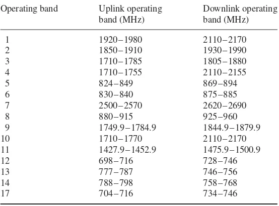
Tables 1.1 and 1.2 list the FDD frequency bands defined in 3GPP for both UMTS and LTE. LTE uses a variable channel bandwidth of 1.4, 3, 5, 10, 15, or 20 MHz. Most common world-wide network deployments are in 5 or 10 MHz, given the bandwidth available in the allocated spectrum for the operator. LTE in 20 MHz is being increasingly deployed, especially in bands like 2.6 GHz as well as 1.8 GHz after frequency re-farming.
Table 1.1 UMTS FDD frequency bands
Operating band and Uplink operating Downlink operating
[band name] band (MHz) band (MHz)
I [UMTS2100] 1920–1980 2110–2170
II [UMTS1900] 1850–1910 1930–1990
III [UMTS1800] 1710–1785 1805–1880
IV [UMTS1700] 1710–1755 2110–2155
V [UMTS850] 824–849 869–894
VI [UMTS800] 830–840 875–885
VII [UMTS2600] 2500–2570 2620–2690
VIII [UMTS900] 880–915 925–960
IX [UMTS1700] 1749.9–1784.9 1844.9–1879.9
X [UMTS1700] 1710–1770 2110–2170
XI [UMTS1500] 1427.9–1452.9 1475.9–1500.9
XII [UMTS700] 698–716 728–746
XIII [UMTS700] 777–787 746–756
XIV [UMTS700] 788–798 758–768
Table 1.2 LTE FDD frequency bands
Operating band Uplink operating Downlink operating
band (MHz) band (MHz)
1 1920–1980 2110–2170
2 1850–1910 1930–1990
3 1710–1785 1805–1880
4 1710–1755 2110–2155
5 824–849 869–894
6 830–840 875–885
7 2500–2570 2620–2690
8 880–915 925–960
9 1749.9–1784.9 1844.9–1879.9
10 1710–1770 2110–2170
11 1427.9–1452.9 1475.9–1500.9
12 698–716 728–746
13 777–787 746–756
14 788–798 758–768
17 704–716 734–746
1.5
LTE Network Architecture
1.5.1
Evolved Packet System (EPS)
3GPP cellular network architecture has been progressively evolving. The target of such evo-lutions is the eventual all-IP systems; migrating from CS-only to CS and PS, up to PS-only all-IP systems. Figure 1.1 summarizes the network architecture evolutions in 3GPP networks. In the 3G network and prior to the introduction of the HSPA system, the network architecture is divided into CS and PS domains. Depending on the service offered to the end-user, the domains interact with the corresponding CN entities. The CS elements are mobile services switching center (MSC), visitor location register (VLR), and Gateway MSC. The PS elements are serving GPRS support node (SGSN) and Gateway GPRS support node (GGSN).
Furthermore, the control plane and user plane data are forwarded between the core and access networks. The RAT in the 3G system uses the WCDMA. The access network includes all of the radio equipment necessary for accessing the network, and is referred to as the universal terrestrial radio access network.
UTRAN consists of one or more radio network subsystems (RNSs). Each RNS consists of an RNC and one or more NodeBs. Each NodeB controls one or more cells and provides the WCMDA radio link to the UE.
After the introduction of HSPA and HSPA+systems in 3GPP, some optional changes have been added to the CN as well as mandatory changes to the access network. On the CN side, an evolved direct tunneling architecture has been introduced, where the user data can flow between GGSN and RNC or directly to the NodeB. On the access network side, some of the RNC functions, such as the network scheduler, have been moved to the NodeB side for faster radio resource management (RRM) operations.
UE eNB
MME
S-GW P-GW
HSS
PCRF
Operators’ IP Services / Internet
LTE Uu
S1-MME
S1-U
S6a
S11
S5 SGi
Gx Sp
Control Plane User Plane Other
eNB
X2
Other MME
S10
Rx
Figure 1.2 Basic EPS entities and interfaces.
Additionally, the IP-multimedia subsystem (IMS) has been defined, earlier before the introduction of LTE, as a PS domain application control plane for the IP multimedia services. It represents only an optional layer/domain that can be used in conjunction with the PS domain/CN.
The LTE network was then introduced as a flat architecture, with user plane direct tunneling between the core and access networks. The EPS system is similar to the flat architecture option in HSPA+. Similar to the 3G system, the LTE system consists of core and access networks, but with different elements and operations.
EPS consists of an E-UTRAN access network and EPC CN. EPS can also interconnect with other RAN; 3GPP (GERAN (GSM/EDGE radio access network), UTRAN) and non-3GPP (CDMA, WiFi, WiMAX).
Though the CS domain is not part of the EPS architecture, 3GPP defines features to allow interworking between EPS and CS entities. This interworking allows traditional services, CS voice speech call, to be set up directly via traditional or evolved CS domain calls, known as CS fallback.
Figure 1.2 shows the basic EPS entities and interfaces. Table 1.3 summarizes the functions of the EPS core and access networks.
1.5.2
Evolved Packet Core (EPC)
EPC includes an MME (mobility management entity), an S-GW (serving sateway), and an P-GW (packet gateway) entities. They are responsible for different functionalities during the call or registration process. EPC and E-UTRAN interconnects with the S1 interface. The S1 interface supports a many-to-many relation between MMEs, S-GWs, and eNBs (eNodeBs) [5]. MME connects to E-UTRAN by means of an S1 interface. This interface is referred to as S1-C or S1-MME [5]. When a UE attaches to an LTE network, UE-specific logical S1-MME connections are established. This bearer, known as an EPS bearer, is used to exchange UE specific signaling messages needed between UE and EPC.
Table 1.3 EPS elements and functions
EPS element Element Basic functionality
EPC (evolved packet core) MME (mobility
management entity)
Signaling and security control Tracking area management
Inter core network signaling for mobility between 3GPP access networks EPS bearer management
Roaming and authentication S-GW (serving gateway) Packet routing and forwarding
Transport level quality of service mapping
P-GW (packet data network(PDN)gateway)
IP address allocation
Packet filtering and policy enforcement User plane anchoring for mobility
between 3GPP access networks E-UTRAN (evolved
universal terrestrial
radio access network)
eNodeB (evolved node B) Provides user plane protocol layers: PDCP, RLC, MAC, physical, and control plane (RRC) with the user Radio resource management E-UTRAN synchronization and
interface control MME selection
messages and by E-UTRAN to send the messages to MME. The identification is released when the UE transitions to idle state where the dedicated connection with the EPC is also released. This process may take place repetitively when the UE sets up a signaling connection for any type of LTE call.
MME and E-UTRAN handles signaling for control plane procedures established for the UE on the S1-MME interface including:
• Initial context set-up/UE context release,
• E-RAB (EPS-radio access bearer) set-up/release/modify, • Handover preparation/notification,
• eNB/MME status transfer, • Paging,
• UE capability information indication.
MMEs can also periodically send the MME loading information to E-UTRAN for mobility management procedures. This is not UE-specific information.
S-GW are connected to E-UTRAN by means of an S1-U interface [5]. After the EPS bearer is established for control plane information, the user data packets start flowing between the EPC and UE through this interface.
a control and user planes. This interface is used when these elements reside within the same PLMN (public land mobile network). In the case of an inter-PLMN connection, the interface between these elements becomes S8 [7].
The details of all the interfaces in EPC and E-UTRAN are further discussed in Section 1.6.
1.5.3
Evolved Universal Terrestrial Radio Access Network (E-UTRAN)
E-UTRAN consists of the eNB. The eNB typically consists of three cells [8]. eNB can, optionally, interconnect to each other via the X2 interface. The interface utilizes functions for mobility and load exchange information [9].
eNB connects with the UE on the LTE-Uu interface. This interface, referred to as the air interface, is based on OFDMA.
E-UTRAN provides the UE with control and user planes. Each is responsible for functions related to call establishment or data transfer. The exchange of such information takes place over a protocol stack defined in UE and eNB. Over the interface between the UE and the EPS, the protocol stack is split into the access stratum (AS) and the non-access stratum (NAS).
1.5.4
LTE User Equipment
Like that of UMTS, the mobile device in LTE is termed the user equipment and is comprised of two distinct elements; the USIM (universal subscriber identity module) and the ME (mobile equipment).
The ME supports a number of functional entities and protocols including:
• RR (radio resource)– this supports both the control and user planes. It is responsible for all low level protocols including RRC (radio resource control), PDCP (packet data convergence protocol), RLC, MAC (medium access control), and PHY layers. The layers are similar to those in the eNB protocol layer.
• EMM (EPS mobility management)– is a control plane entity which manages the mobility states of the UE: LTE idle, LTE active, and LTE detached. Transactions within these states include procedures such as TAU (tracking area update) and handovers.
• ESM (EPS session management)– is a control plane activity which manages the activa-tion, modificaactiva-tion, and deactivation of EPS bearer contexts. These can either be default or dedicated EPS bearer contexts.
The PHY layer capabilities of the UE may be defined in terms of the frequency bands and data rates supported. Devices may also be capable of supporting adaptive modulation including QPSK, 16QAM, and 64QAM. Modulation capabilities are defined separately in 3GPP for uplink and downlink.
The UE is able to support several scalable channels, including 1.4, 3, 5, 10, 15, and 20 MHz, while operating in FDD and/or TDD. The UE may also support advanced antenna features such as MIMO with a different number of antenna configurations.
Table 1.4 LTE UE categories
UE category 3GPP release Downlink Uplink
Maximum data Maximum number Maximum data Support for rate (Mbps) of layers rate (Mbps) 64QAM
Category 1 Release 8/9 10 1 5 No
Category 2 Release 8/9 51 2 25 No
Category 3 Release 8/9 102 2 51 No
Category 4 Release 8/9 150 2 51 No
Category 5 Release 8/9 300 4 75 Yes
Category 6 Release 10 301 2 or 4 51 No
Category 7 Release 10 301 2 or 4 102 No
Category 8 Release 10 3000 8 1500 Yes
1.6
EPS Interfaces
This section summarizes the EPS interfaces and relevant protocols, with reference to the over-all architecture in Figure 1.2. The main protocols used inside EPS interfaces are summarized as follows:
• S1 application protocol (S1-AP)– Application layer protocol between the eNB and the MME.
• Stream control transmission protocol (SCTP)– This protocol guarantees delivery of sig-naling messages between MME and eNB (S1). SCTP is defined in [11].
• GPRS tunneling protocol for the user plane (GTP-U)– This protocol tunnels user data between eNB and the SGW, and between the SGW and the PGW in the backbone network. GTP will encapsulate all end-user IP packets.
• User datagram protocol (UDP)– This protocol transfers user data. UDP is defined in [12]. • UDP/IP– These are the backbone network protocols used for routing user data and control
signaling.
• GPRS tunneling protocol for the control plane (GTP-C)– This protocol tunnels signal-ing messages between SGSN and MME (S3).
• Diameter– This protocol supports transfer of subscription and authentication data for authenticating/authorizing user access to the evolved system between MME and HSS (home subscriber service) (S6a). Diameter is defined in [13].
1.6.1
S1-MME Interface
S1-AP
SCTP
IP
L2
L1
eNodeB S1-MME MME
S1-AP
SCTP
IP
L2
L1
Figure 1.3 Control plane for eNB (S1-MME). (Source: [5] 3GPP TS 2010. Reproduced with per-mission of ETSI.)
One logical S1-AP connection per UE is established and multiple UEs are supported via a single SCTP association. The following functionalities are conducted at S1-AP:
• Set up, modification and release of E-RABS. • Establishment of an initial S1 UE context. • Paging and S1 management functions.
• NAS signaling transport functions between UE and MME. • Status transfer functionality.
• Trace of active UEs, and location reporting.
• Mobility functions for UE to enable inter- and intra-RAT HO.
1.6.2
LTE-Uu Interface
The radio protocol of E-UTRAN between the UE and the eNodeB is specified in [14]. The user plane and control plane protocol stacks for the LTE-Uu interface are shown in Figures 1.4 and 1.5, respectively. The protocols on E-UTRAN-Uu (RRC, PDCP, RLC, MAC, and the PHY LTE layer) implements the RRM and supports the NAS protocols by transporting the NAS messages across the E-UTRAN-Uu interface.
The protocol stack layer and air interface functions are described in detail in Chapter 2.
PDCP UE
RLC
MAC
PHY
PDCP eNB
RLC
MAC
PHY
NAS
Figure 1.5 Control-plane protocol stack. (Source: [14] 3GPP TS 2009. Reproduced with permission of ETSI.)
Figure 1.6 User plane of S1-U. (Source: [15] 3GPP. Reproduced with permission of ETSI.)
Application
UE eNodeB Serving GW PDN GW
LTE-Uu S1-U S5/S8 SGi
L1
![Figure 1.9Protocol stack for S3 interface between MME and SGSN. (Source: [6] 3GPP TS 2011.Reproduced with permission of ETSI.)](https://thumb-ap.123doks.com/thumbv2/123dok/4027321.1970741/48.482.157.316.490.591/figure-protocol-stack-interface-sgsn-source-reproduced-permission.webp)
![Figure 1.18Control plane for S10 interface between MMEs. (Source: [17] 3GPP TS. Reproducedwith permission of ETSI.)](https://thumb-ap.123doks.com/thumbv2/123dok/4027321.1970741/53.482.168.324.492.599/figure-control-plane-interface-mmes-source-reproducedwith-permission.webp)