i
BACHELOR THESIS - ME141501
ENVIRONMENTAL RISK ASSESSMENT OF COAL
LOADING IN LUBUK TUTUNG KALIMANTAN
TIMUR COAL TERMINAL
FAISHAL RACHMAN NRP 4212 100 137
Supervisor
A.A.B. Dinariyana D.P., S.T., MES., Ph.D. Dr. Kriyo Sambodho, S.T., M.Eng.
DEPARTMENT OF MARINE ENGINEERING Faculty of Marine Technology
iii
SKRIPSI - ME141501
ANALISA
RISIKO
LINGKUNGAN
DARI
PEMUATAN
BATUBARA
DI
TERMINAL
BATUBARA LUBUK TUTUNG KALIMANTAN
TIMUR
FAISHAL RACHMAN NRP 4212 100 137
Dosen Pembimbing
A.A.B. Dinariyana D.P., S.T., MES., Ph.D. Dr. Kriyo Sambodho, S.T., M.Eng.
DEPARTEMEN TEKNIK SISTEM PERKAPALAN Fakultas Teknologi Kelautan
ix I, who signed below hereby confirm that:
This final project report has written without any plagiarism act, and confirm consciously that all the data, concepts, design, references, and material in this report own by Reliability, Availability, Maintainability and Safety (RAMS) in Department of Marine Engineering ITS which are the product of research study and reserve the right to use for further research study and its development.
Name : Faishal Rachman
NRP : 4212 100 137
Bachelor Thesis Title: Environmental Risk Assessment of Coal Loading in Lubuk Tutung Kalimantan Timur Coal Terminal
Department: Marine Engineering
If there is plagiarism act in the future, I will fully responsible and receive the penalty given by ITS according to the regulation applied.
Surabaya, 7 January 2017
xi
TIMUR COAL TERMINAL
Name : Faishal Rachman
NRP : 4212 100 137
Department : Marine Engineering
Supervisor :
1. A.A.B. Dinariyana D.P., S.T., MES., Ph.D.
2. Dr. Kriyo Sambodho, S.T., M.Eng.
Abstract
Indonesian government has committed to build mega project power plant in 2015 – 2019 to provide 35.000 Megawatts (MW) for Indonesia. Many power plants would be built across Indonesia area. Some of power plants is coal – fuel power plant. Therefore, it is really necessary for Indonesia to have enough coal stock to supply power plants. Port plays a key role to maintain coal stock. Ships that carrying coal would perform loading and unloading process in port. Because the volume of coal that moved in a day is quite large, the potential of the danger incurred in the loading and process will getting bigger. Therefore, it is important to assess hazard around port when ship perform loading and unloading process.
and do a consequence of analysis simulations with vertical suspended – sediment distributions graphic. After it is done, will obtained the results of the risk assessment. Risk assessment level in the risk acceptance matrix based on the framework provided from KPC Risk Rank. The accidents mainly caused by human error, rough environment and equipments failure. Based on the frequency analysis, there are no accidents considered as high frequency level.
Based on the consequence analysis, it occurred varied results. The level of concequence are varied from low risk to high risk. Based on the risk analysis, there is one accident considered as high risk, the accident that considered as high risk is collision of barge with bulk carrier. Therefore, it is necessary to do the mitigation. The mitigation based on DNV (Det Norske Veritas) mitigation strategies.
xiii
BATUBARA LUBUK TUTUNG KALIMANTAN
TIMUR
Nama : Faishal Rachman
NRP : 4212 100 137
Departemen : Teknik Sistem Perkapalan Dosen Pembimbing :
1. A.A.B. Dinariyana D.P., S.T., MES., Ph.D. 2. Dr. Kriyo Sambodho, S.T., M.Eng.
Abstrak
Pemerintah Indonesia telah berkomitmen untuk membangun mega project power plant pada 2015 – 2019 dengan tujuan menyediakan 35.000 Megawatts (MW) untuk Indonesia. Banyak power plant yang akan dibangun sepanjang wilayah Indonesia. Maka dari itu, sangat penting bagi Indonesia untuk mempunyai ketersediaan batubara untuk menyuplai power plant. Pelabuhan memainkan peranan penting pada ketersediaan batubara. Kapal – kapal yang mengangkut batubara akan melakukan proses pemuatan dan pembongkaran di pelabuhan. Karena jumlah dari batubara yang berpindah dalam sehari cukup besar, potensi bahaya yang timbul dari pemuatan batubara akan semakin besar. Maka dari itu, penting untuk menganalisa bahaya di sekitar pelabuhan ketika melakukan proses pemuatan dan pembongkaran.
penyebab bahaya yang terjadi di fasilitas, kemudian analisa frekuensi menggunakan metoda FTA (fault tree analysis), dan melakukan analisa simulasi konsekuensi dengan vertical sediment distributions graphic. Setelah itu dilakukan, akan didapatkan hasil dari analisa risiko. Tingkat penilaian risiko pada risk acceptance matrix berdasarkan pada matrix yang telah diberikan dari KPC Risk Rank. Penyebab utama kejadian disebabkan oleh human error, lingkungan yang tidak kondusif dan kegagalan peralatan. Berdasarkan analisa frekuensi, tidak ada kecelakaan yang dianggap tingkat frekuensi tinggi.
Tingkat konsekuensi bervariasi, dari yang rendah sampai tinggi. Berdasarkan analisa risiko, ada satu kecelakaan yang dianggap risiko tinggi, yakni tubrukan tongkang dengan bulk carrier. Maka dari itu, penting untuk melakukan mitigasi. Mitigasi berdasarkan strategi mitigasi DNV (Det Norske Veritas).
xv
Thanks to the presence of Allah SWT for everything that have given to me, which has given guidance so that the Bachelor Thesis with title "
Environmental Risk Assessment of Coal
Loading in Lubuk Tutung Coal Terminal”
can be resolvedproperly. In completing this the Bachelor Thesis, I can’t do it alone. Therefore, I would like to thank those who have helped in completing this Bachelor Thesis, among others:
1. My mother, Murdianah, for all the support and love you have given to me. I am forever grateful. My father, Arief Hermawan Mansur, for always guide me like the first time I
got a problem. You’re the best dad in the world. My sisters,
Nurul Annisa and Nuzul Novianti who has helped me grow to be a better person.
2. A.A.B. Dinariyana D.P., S.T., MES. Ph.D., as my first supervisor in Bachelor Thesis. For constant help and pushing me to move forward during all phases of my work. I am deeply grateful.
3. Dr. Kriyo Sambodho, S.T., M.Eng., as my second supervisor in Bachelor Thesis. Thank you for being so patient with me during all phases of my work. I am eternally grateful. 4. Ir. Hari Prastowo, M.Sc., as my father in Department of
Marine Engineering. Thank you for your kindness and help, particularly during my student exchange program. I am deeply indebted.
5. Prof. Dr. Ketut Buda Artana, S.T., M.Sc., Raja Oloan Saut Gurning, S.T., M.Sc., Ph.D., Beny Cahyono, S.T., M.T., Ph.D. as my examiners at my bachelor thesis defense. Thank you for all the valuable comments and guidance.
taught me many valuable things to become a good marine engineering student.
7. Emmy Pratiwi, S.T., Fadilla Indrayuni Prastyasari, S.T., M.Sc., Ayudhia Pangestu Gusti, S.T., Putri Dyah Setyorini, S.T. and Gede Bagus Dwi Suasti Antara, S.T., M.M.T. as my mentors during my research study in RAMS Laboratory, that helped me with valuable comments and guidance. Thank you for being so patient with me.
8. PT. Dire Pratama, particularly to Aji Wardoyo, Addo Yani, Widi Miharno, Nirmawati, Muhammad Aufar, Rofano, Tenang Prasetyo, Hendra, Koes Hendratmo, Ahmad Yani and Edward. For letting me take data survey and opportunity to discuss coal handling operation.
9. Aulia Hashemi Farisi, Faris, Ilham Nurhakim and Try Ahmad Mirza, as my friends since 2010. For being a friends and rivals to reach our own goals. Thank you for helped me during my ups and downs.
10. Ahmad Jauhar Isnan, Georgius Suhud, Muhammad Farhan Yusuf Amir, Muhammad Nuraga Lazuardy Ramadhan, Rani Eva Dewi and Salman Alfarisi, as my friends during my college life. Thank you for being there for me, during good and hard times.
11. Nyimas Safira Amalia, Dante Taufiq Akbar, Libryan Qadhi Razi, Ricard Diago Sambuaga, Kevin Kurniawan, and other
RAMS Lab’s members as my friends in RAMS Laboratory.
For a pleasant and inspiring atmosphere.
12. Arief Maulana, Ario Danurdoro Widodo, Felix Rizky Aditia, Cabinet and members of HIMASISKAL ITS 2014 – 2015. 13. My ex – girlfriends, to helped me become a better man for
another woman who deserve me.
xvii
APPROVAL FORM ... v
APPROVAL FORM ... vii
DECLARATION OF HONOR ... ix
ABSTRACT ... xi
PREFACE ... xv
TABLE OF CONTENTS ... xvii
LIST OF FIGURES ... xix
LIST OF TABLES ... xxi
CHAPTER I INTRODUCTION ... 1
1.1 Background ... 1
1.2 Problem Formulation and Scope ... 5
1.3 Research Objectives ... 6
1.4 Research Benefits ... 6
CHAPTER II BASIC THEORY ... 7
2.1 Theory ... 7
2.1.1 About PT. Dire Pratama Coal Terminal ... 7
2.1.2 Loading and Unloading of Bulk Carriers ... 8
2.1.3 Environmental Assessment ... 9
CHAPTER III METHODOLOGY ... 23
3.1 Methodology Flow Chart ... 23
3.2 Background ... 24
3.3 Literature Study ... 24
3.6 Frequency Analysis ... 24
3.7 Consequence Analysis ... 25
3.8 Risk Analysis ... 25
3.9 Mitigations ... 25
3.10 Conclusion ... 25
CHAPTER IV DATA ANALYSIS AND DISCUSSION ... 27
4.1 General Description ... 27
4.2 Data ... 27
4.3 Hazard Survey ... 33
4.4 Frequency Analysis ... 38
4.4.1 Collision Frequency ... 43
4.4.2 Grounding Frequency ... 54
4.4.3 Total Coal Loss Frequency ... 64
4.5 Consequence Analysis ... 66
4.6 Risk Analysis ... 71
CHAPTER V CONCLUSION ... 79
REFERENCES ... 81
ATTACHMENT ... 85
xix
xxi
Table 2.1 Recommendation Layout of Checklist ... 9
Table 2.2 Comparison of Hazard Identification methods (1) (Source: Risk Management, 2015) ... 13
Table 2.3 Comparison of Hazard Identification methods (2) (Source: Risk Management, 2015) ... 14
Table 4.1 Technical Data of Coal Loading Process in Lubuk Tutung Coal Terminal ... 31
Table 4.2 Hazard Survey Discussion Attendees... 34
Table 4.3 Hazards Identified ... 35
Table 4.4 Descriptive Screening of Possible Accidents in Lubuk Tutung ... 42
Table 4.5 Total Vessel in Lubuk Tutung Port Water Area in 2016 ... 44
Table 4.6 Calculation of Cumulative Collision Frequency for Barge and Bulk Carrier... 51
Table 4.7 Calculation of Cumulative Collision Frequency for Barge and Coal Jetty... 54
Table 4.8 Total Vessel in Lubuk Tutung Port Water Area in 2016 ... 55
Table 4.9 Probability Barge Hits the Obstacle ... 61
Table 4.10 Grounding Frequency of Barge ... 61
Table 4.11 Probability Bulk Carrier Hits the Obstacle ... 63
Table 4.12 Grounding Frequency of Bulk Carrier ... 64
Table 4.13 Results for Coal Loss Frequency... 65
Table 4.14 Sediment Concentration Profile Calculated Using Equation 4.12 ... 69
Table 4.15 Regulation for Wastewater Concentration ... 69
Table 4.16 Risk Results ... 76
1
CHAPTER I
INTRODUCTION
1.1 Background
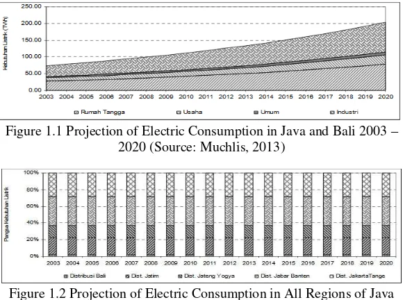
Indonesian government has committed to build mega project power plant in 2015 – 2019 to provide 35.000 Megawatts (MW) for Indonesia (Muchlis, 2013). Many power plants would be built across Indonesia area. Some of power plants is coal – fuel power plant. Therefore, it is really necessary for Indonesia to have enough coal stock to supply the power plants.
Figure 1.1 Projection of Electric Consumption in Java and Bali 2003 – 2020 (Source: Muchlis, 2013)
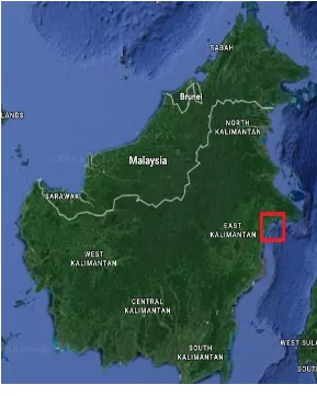
Figure 1.2 Projection of Electric Consumption in All Regions of Java and Bali 2003 – 2020 (Source: Muchlis, 2013)
across Indonesia area. This coal company have their own coal terminal to deliver its coal stock to another area in Indonesia.
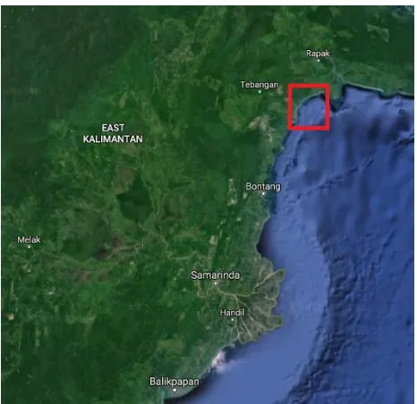
Figure 1.4 Map of Kalimantan Timur (Source: Google Earth, 2016)
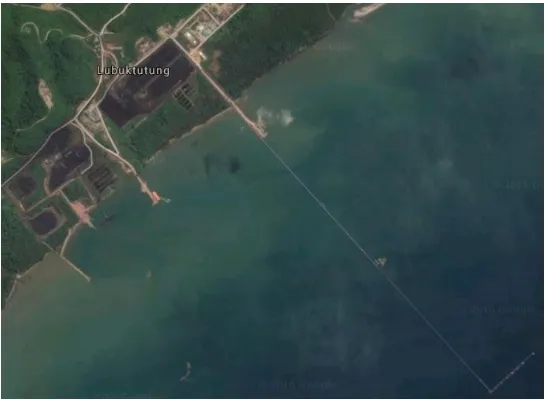
Figure 1.6 Map of PT. Dire Pratama Coal Terminal (Source: Google Earth, 2016)
the possibility of collision, grounding, toxic release, fire and spilling accident that can cause casualties and environmental damage (Newcastle Coal Infrastructure Group, 2006).
The process of risk assessment consisting of identify hazard, analysis possible causes of danger that would happen in facilities, then frequency analysis, and do a consequence of analysis simulations with vertical suspended – sediment distributions graphic. After it is done, will obtained the results of the risk assessment. Risk assessment level in the risk acceptance matrix based on the framework provided from KPC Risk Rank. If the risk is unacceptable, then mitigation should be taken to reduce the risk that can cause casualties and environmental damage.
1.2 Problem Formulation and Scope
From the explanation above, so the main problem will be discussed is as follows:
a. How to identify hazard around coal terminal when ships perform loading process based on hazard survey?
b. What is the level frequency of risk that occurred at the coal loading process?
c. What is the level consequence of risk that occurred at the coal loading process?
d. How is the result of risk level in the risk acceptance matrix based on the framework provided from KPC Risk Rank? e. How is mitigation recommendations (if necessary) based
on DNV Risk Mitigation Strategies?
The stated scopes of this study are:
a. Analysis risk due to failure of the system.
1.3 Research Objectives
The objectives of this study are to:
a. Identify hazard around coal terminal when ships perform loading process based on Hazard Survey.
b. Analysis frequency of risk that occurred at coal loading process by using FTA (Fault Tree Analysis) method. c. Analysis consequence of risk that occurred at coal loading
process by using vertical suspended – sediment distributions graphic.
d. Be informed about the result of risk level in the risk acceptance matrix based on the framework provided from KPC Risk Rank.
e. Be informed about mitigation recommendations (if necessary) based on DNV Risk Mitigation Strategies.
1.4 Research Benefits
The benefits of this study are:
a. Could provide recommendations about the risk of coal loading process to PT. Dire Pratama Coal Terminal. b. Could be used by the related parties to determine the act of
7
CHAPTER II BASIC THEORY
2.1 Theory
2.1.1 About PT. Dire Pratama Coal Terminal
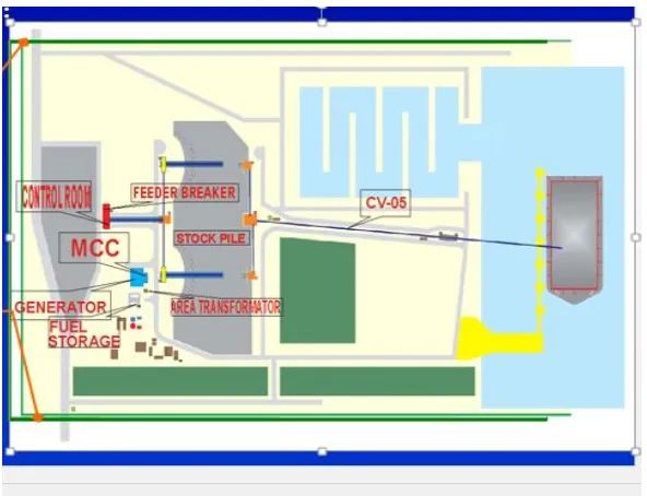
PT. Dire Pratama coal terminal is one of the coal supplier in Kalimantan that plays significant role to maintain coal stock for Indonesia. One of its key advantages is that it has port link road. Among the facilities that it offers are a stockpile, conveyors, and a feeder breaker.
Figure 2.2 Coal Terminal (Source: PT. Dire Pratama Coal Terminal, 2015)
2.1.2 Loading and Unloading of Bulk Carriers
The safety of bulk carriers at terminals in order to load or unload solid bulk cargoes, by reducing the risks of excessive stresses and physical damage to the ship's structure during loading or unloading, through the establishment of:
• Suitability requirements for those ships and terminals, and
• Procedures for co-operation and communication between those ships and terminals.
Schedule for Loading and Unloading of Bulk Carriers:
d. Responsibilities of the terminal representative e. Procedures between bulk carriers and terminals
f. Repair of damage incurred during loading and unloading g. Role of competent authorities
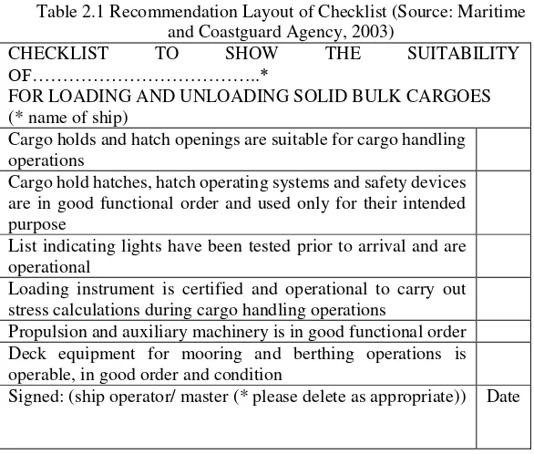
Table 2.1 Recommendation Layout of Checklist (Source: Maritime and Coastguard Agency, 2003)
CHECKLIST TO SHOW THE SUITABILITY
OF………..*
FOR LOADING AND UNLOADING SOLID BULK CARGOES (* name of ship)
Cargo holds and hatch openings are suitable for cargo handling operations
Cargo hold hatches, hatch operating systems and safety devices are in good functional order and used only for their intended purpose
List indicating lights have been tested prior to arrival and are operational
Loading instrument is certified and operational to carry out stress calculations during cargo handling operations
Propulsion and auxiliary machinery is in good functional order Deck equipment for mooring and berthing operations is operable, in good order and condition
Signed: (ship operator/ master (* please delete as appropriate)) Date
2.1.3 Environmental Assessment
It is important therefore, that where there are particular marine operations, such as specialist one-off towage, vessel movements or new trades, which fall outside the scope of the Safety Management System (SMS), those operations are assessed to determine the likely risk to navigational safety. In addition to establish what, if any, additional or new risk control measures are required to reduce that risk to an acceptable level. The district Harbour Master will advise operators if any such operation or trade falls in that category. This study provides operators and owners with an overview of the environmental risk assessment.
The attitude to safety in Indonesia has evolved over recent decades from the reactive to the proactive. The Health and Safety Executive has promoted a common approach to safety across all the industries it regulates (Adnyana, 2012). In the past, safety regulation was introduced as the result of an accident or a series of accidents and tended to address the most obvious causes. However, over the years a number of defining incidents have altered the way in which safety is viewed.
Indonesia has now progressed to a risk based approach to commercial safety that aims to identify risks and control them, and to do this in a way that constantly updates the risks in any given process or operation. These principles can be applied readily to navigation in restricted tidal waters and rivers.
Safety is the business of all concerned, around which the entire operation must function. Involving crews and staff, and where necessary external advice, in the risk assessment; and utilising specialist knowledge and skills is essential, especially in the identification of hazards and the development or refinement of procedures and defences to mitigate those risks.
Definitions:
• Hazard is something that has the potential to cause harm.
The risk assessment will typically involve five stages: A. Data Gathering and Familiarisation
B. Hazard Identification C. Risk Analysis D. Risk Assessment E. Risk Control
A. Data Gathering and Familiarisation
This initial stage has two main objectives: to become wholly familiar with the particular operation in question and also, where necessary; the organisation, its culture, policies, procedures, issues and priorities, and to assess the existing (vessel/organisational) safety management structure and identify any relevant hazards and risks (Maritime Safety Authority of New Zealand, 2004). The work should include, but not be limited to:
a. A review of current (and relevant) organisational and vessel management and operational procedures;
b. A thorough assessment of the operation(s) in question from a safety of navigation perspective;
c. Interviews with the vessel skipper, crew, management and where necessary contractors or principals;
d. Auditing of selected marine/navigational safety procedures;
e. A review of the requirements, limitations, and technical and contractual requirements of the operation/trade in question; and
B. Hazard Identification (Hazard Survey)
This phase seeks to build on the work of Stage A and identify known hazards expected to be encountered because of the nature and/or area of the operation, and the existing risk control measures relating to those hazards. Equally importantly, it also seeks to identify any new hazards created as a result of the proposed service or operation. Structured Hazard Identification meetings (HAZIDs) should be held involving relevant marine staff, management, relevant customers or principals.
This approach recognises that the people best placed to identify hazards are often personnel working within the port, but
that a “new pair of eyes” also notices items of significance that are
accepted as normal in the system. The benefits provided by those outside pair of eyes are very important to the success of the risk assessment. It is perhaps obvious that risk assessments undertaken totally in-house do not generally address all the issues, some of which will be related to problems that the organisation with responsibility has hesitation in addressing (Anatec Ltd., 2012).
The HAZID process should be conducted on an Incident Category basis, across each area of the port. It should systematically consider vessel types, operations and interfaces appropriate to each area. The approach will be to undertake a general Hazard Identification on a geographical basis, followed by a number of smaller meetings concentrating on specific areas and assessment of specific operations. Hazards should be identified initially on a generic basis and then added, in order to consider scenarios specific to different areas of the port.
Table 2.2 Comparison of Hazard Identification methods (1) (Source: Risk Management, 2015)
Method Data Sources Attributes Application
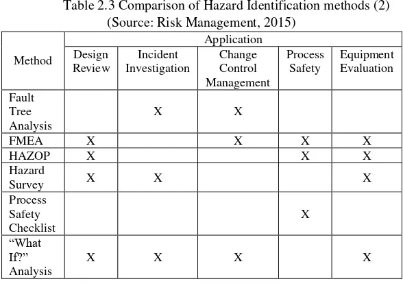
Table 2.3 Comparison of Hazard Identification methods (2) (Source: Risk Management, 2015)
Method
C. Risk Analysis
Stage 3 introduces the concept of risk in a qualitative way in order to prioritise the hazards identified during Stage B and assess their impact on navigational safety. As shown above, risk is the combination of frequency and consequence. Prioritisation is an essential part of the process, as clearly, the greater the potential posed by a hazard, the greater the need to ensure that there are control measures, or defences, in place to mitigate that risk.
Sorting and ranking the HAZID output and adding the frequency component (i.e. how often such a hazard could happen –
once a year, once every 10 years; 100 years 1000 years…)
operations. Normally, risks are assessed in four ways against a common frequency scale:
a.
consequence to life;
b.
consequence to the environment;
c.
consequence to port authority operations; and
d.
consequence to port users.
Such an approach not only assesses the impact of
hazards on port safety, but also their impact on other
important areas of the port infrastructure.
D. Risk Assessment
This process compares existing operations and procedures supported by relevant control measures with the new risk profile created by the introduction of the new trade or operation. It identifies gaps, which will require the introduction of new or enhanced risk control measures to reduce the level of risk to an acceptable level.
All activities entail an element of risk. A risk assessment can be defined as the determination of the quantitative or qualitative value of risk related to specific situations and hazards. In practical terms, a risk assessment is a thorough examination and identification of the situations and processes that may cause harm to people, environment, business and property.
Risk assessment in this study has aims to determine the level of risk that can be generated in the loading coal, by using FTA (Fault Tree Analysis).
diagrams are a graphical design technique. An fault tree diagram is built top-down and in term of events rather than blocks. It uses a graphic "model" of the pathways within a system that can lead to a foreseeable, undesirable loss event (or a failure). The pathways connect contributory events and conditions, using standard logic symbols (AND, OR, etc.). The basic constructs in a fault tree diagram are gates and events.
Figure 2.3 Fault Tree Diagram
Assess the potential risks from the following accident types:
a. Ship-ship collision: A contact between two or more vessels under way.
b. Powered grounding: Groundings that occur when the ship is under power and has the ability to navigate safely yet goes aground (e.g. due to human error).
c. Drift grounding: Groundings that occur when the ship is unable to navigate safely, usually due to mechanical failure and is forced on to the shoreline by the action of wind, current or waves.
e. Structural failure or foundering while a vessel is underway. f. Impact: An accident that typically occurs during approach or departure, when a ship impacts the berth with force sufficient to damage the ship or the berth.
g. Striking: A contact between a navigating ship and a ship moored at the berth.
A vertical suspended – sediment distributions graphic for assessing the risks of marine environment is used to assist with the PT. Dire Pratama coal terminal traffic assessment. The following natural environment data is used by the vertical suspended – sediment distributions graphic:
a. Visibility. This affects the collision and powered grounding accident models.
b. Wind speed and direction. This affects the drift grounding accident model if a water current is not applied.
c. Wave height (sea state). This affects the structural failure/ foundering accident model.
d. Sea bottom and coastal or river bank characterization. This affects the drift and powered grounding accident model. e. Open water or river water. This affects the severity of the
accident consequences for collision, powered and drift grounding and structural failure/ foundering accidents because such accidents are less likely to result in severe damage to the vessel in a sheltered river location compared to open water.
f. Currents.
environmental compartments. Most sediment in surface waters derives from surface erosion and comprises a mineral component, arising from the erosion of bedrock, and an organic component arising during soil-forming processes (United Nations Environment Programme, 1996). An additional organic component may be added by biological activity within the water body.
For the purposes of aquatic monitoring, sediment can be classified as deposited or suspended. Deposited sediment is that found on the bed of a river or lake. Suspended sediment is that found in the water column where it is being transported by water movements. Suspended sediment is also referred to as suspended matter, particulate matter or suspended solids (United Nations Environment Programme, 1996). Generally, the term suspended solids refer to mineral and organic solids, whereas suspended sediment should be restricted to the mineral fraction of the suspended solids load.
Parameter that will be used for this graphic is Ministerial
Decree of Indonesia’s Ministry of Environment number 1 in 2010. This Ministerial Decree regulates water quality in coal business.
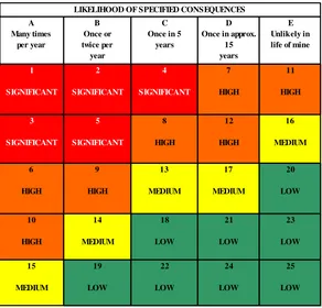
The risk analysis was used to evaluate the overall risks of these accidents. This step relied on a risk acceptance matrix. The risk acceptance matrix is developed based on the framework provided from KPC Risk Rank. The frequency of each accident was categorized from Many Times Per Year (A) to Unlikely in Life of Mine (E). Their consequence was assessed with regards to their potential impact to:
The consequences were then rated from Long-Term Impact (1) to Minor Impact (5).
Figure 2.5 Consequence Matrix used to Evaluate Risk Assessment Results
HEALTH CONSEQUENCES SAFETY CONSEQUENCES
Long term chronic health effects to workers or public with potential for death
Fatality (Fatality, multiple
fatality; major permanent disability)
Property Damage / >$ US 500k
More than 1week delay production
Large-scale, long-term environmental damage offsite and / or a compliance breach that threatens continued operation
2
Long term chronic health effects to workers or public with major impact on body function / lifestyle
LDI (Serious injury and
hospitalization; permanent disability)
Property Damage / > $
US 100 – 500 K 3 – 6 day delay production
Large-scale, short-term environmental damage offsite and / or a compliance breach sanction
3 Chronic health effects causing partial impact on body function
RWDI
(Minor loss of body part / function; LTI)
Property Damage / > $
Health impact requiring medical treatment / intervention; not permanent
Medical treatment
(Treatment that must be given by a doctor)
Property Damage / $ US
1 – 50 k 1 – 3 shift delay production
Significant environmental damage onsite only and / or a technical compliance breach
5 Transitory health impact
Minor impact
(First aid treatment)
Property Damage < $ US
1000 1 shift delay production
Figure 2.6 Risk Acceptance Matrix used to Evaluate Risk Assessment Results
The risk analysis was used to evaluate the overall risks of these accidents. This step relied on a risk acceptance matrix. The risk acceptance
Each accident type was then mapped onto the risk matrix to provide its overall risk level as per the following colours:
Green (Low risk number 18 to 25): Risk is tolerable, Once in approx.
considered for implementation. Take corrective actions as considered necessary.
Yellow (Medium risk number 13 to 17): Risk is As Low as
Reasonably Possible (ALARP) if all justified risk reduction measures have been implemented. Take corrective action within a reasonable timeframe and control measure to be reviewed where appropriate. Orange (High risk number 6 to 12): Take corrective /
preventive action immediately and control measures to be reviewed or established by management.
Red (Significant risk number 1 to 5): Stop the activity, take corrective / preventive action immediately and only recommence the activity when controls are in place.
E. Risk Control
23
CHAPTER III METHODOLOGY
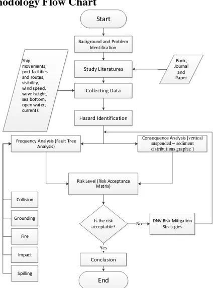
To assist in the implementation of this thesis, it is necessary to make a sequence of method into the terms of reference in the implementation of the tasks of this thesis. This methodology as shown in Figure 3.1 contains steps taken to address the problems of the work of this thesis. Starting from identification of problems to eventually get a conclusion for the working of this thesis.
3.1 Methodology Flow Chart
Start
Background and Problem Identification
Consequence Analysis (vertical suspended – sediment distributions graphic ) Frequency Analysis (Fault Tree
Analysis)
Risk Level (Risk Acceptance Matrix)
Is the risk acceptable?
End
DNV Risk Mitigation Strategies
3.2 Background
Before conducting the research, at first the background of this study will be explained.
3.3 Literature Study
The literature study is an early stage is the stage of learning about the basic theories to be discussed or used in the thesis. Source taken at this stage comes from books, papers, websites, journals, and so forth.
3.4 Data Collection
This phase is to obtain information that related to coal loading process in port.
3.5 Hazard Identification
This phase seeks to identify known hazards expected to be encountered because of the nature and/or area of the operation, and the existing risk control measures relating to those hazards. Equally importantly, it also seeks to identify any new hazards created as a result of the proposed service or operation.
3.6 Frequency Analysis
3.7 Consequence Analysis
The process of examining the possible effects of a planned activity. This study examining the possible effects of marine hazards caused in coal loading process in port using vertical suspended – sediment distributions graphic.
3.8 Risk Analysis
The risk analysis was used to evaluate the overall risks of accidents. This step relied on a risk acceptance matrix. The risk acceptance matrix is developed based on the framework provided from KPC Risk Rank.
3.9 Mitigations
This stage identifies the specific control measures to be adopted. DNV Risk Mitigation Strategies techniques are used at this stage to support the identification and choice of recommendations.
3.10 Conclusion
27
CHAPTER IV
DATA ANALYSIS AND DISCUSSION
4.1 General Description
This bachelor thesis’ research object is coal terminal that belongs to PT. Dire Pratama. This coal terminal facility is located in Lubuk Tutung, Bengalon Coal Project, Bengalon, Kutai Timur, Kalimantan Timur, Indonesia. Coal loading process will be carried by barge and bulk carrier ships that come from outside Kalimantan Timur region. This survey data analysis below is collected in Lubuk Tutung coal terminal at 3rd– 8th October 2016.
4.2 Data
Data which needed for this bachelor thesis are:
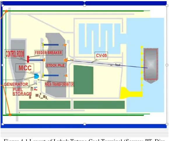
a. Layout of Lubuk Tutung Coal Terminal, Bengalon Coal Project, Bengalon, Kutai Timur, Indonesia
Figure 4.1 Layout of Lubuk Tutung Coal Terminal (Source: PT. Dire Pratama, 2015)
b. Operational steps of coal loading process
Coal loading process in Lubuk Tutung coal terminal has several steps, which are:
The dust suppression system for the hopper is controlled by an infrared sensor which detects a truck when in the hopper dump position.
A Stamler Feeder Breaker FB-01 is located under the ROM Hopper and is designed to handle a maximum of 1-meter sized coal lumps. There is a grizzly grille fitted at the top of the Hopper to eliminate any lumps larger than 1 meter. These lumps must be broken up or removed manually.
Coal from the FB 01 is discharged on to conveyor No.1 (CV-01) where it is carried 70 meters to the top of the Sizer Tower. CV-01 has a 1400 mm wide belt which travels at 4.25 m/s. CV-01 has a design capacity of 2000 tons/hour.
Coal from the CV 01 is discharged on to conveyor No.1A (CV-01A) where it is carried 42 meters to the top of the Sizer Tower. CV-01A has a 2400 mm wide belt which travels at 1.8 m/s. CV-01A has a design capacity of 2000 tons/hour.
CV-01A has a metal Detector which will remove most metals, however if metal is still in the coal stream a metal detector fitted with a paint spay will mark the location of the metal object on the top of the coal stream and automatically shut down the conveyor. The Stamler Sizer (CR-01) has a nominal capacity of
Conveyor CV-02 transports coal from the Stamler Sizer CR-01 to Stackers ST-01 or ST-02. CV-02 is 1200 mm wide and a travel at 5.25 m/s. CV-02 has a capacity of 2000 tons/hour of coal. CV-02 conveyor has a reversible belt that can feed to only one Stacker at a time.
Stackers ST-01 & ST-02 transport coal from CV-02 to the Product Stockpiles Each stockpile has a coal storage capacity of 60,000 m³ (total 120,000 m³)
which, with stockpile ‘push-out’, is expected to increase to some 80,000 m³.
The Reclaimers RC-01 & RC-02 have a rated capacity of some 3,000 tons/hour, but in this application they will nominally run up to 2,000 tons/hour of coal. Coal will be loaded from the Product Stockpiles by a bulldozer (or equivalent) into the respective intake plates of each Reclaimer. The coal is then picked up by a drag conveyor and moved through the machine to a discharge chute which will dump the coal onto either CV-03 for RC-01 or CV-04 for RC-02, depending on which Reclaimer is in operation at the time.
Both Reclaimers & associated conveyor can be operated together with course blending of coals being possible on to CV-05.
Conveyors CV-03 & CV-04 transport coal from the Stamler Reclaimers RC-01 and RC-02 to the Barge Loading Conveyor CV-05.
04 is shutdown due to activation of the metal detectors, the corresponding Reclaimer will also shut down. If CV-05 is also tripped for any reason, the currently
operating conveyor/s and reclaimer/s will also be shutdown.
Conveyor CV-05 has a 1,400 mm wide belt traveling at a speed of 5.5 m/s with a nominal capacity of 2000 tons/hour of coal. CV-05 is equipped with a Belt Scale BS-2, which totalizes the amount of coal delivered to the Coal Barges.
CV-05 also has the capability of variable speed. This is controlled locally & via the PLC from the control room.
c. Technical data of coal loading process
Several data of coal loading process in Lubuk Tutung coal terminal could be seen in Table 4.1.
Table 4.1 Technical Data of Coal Loading Process in Lubuk Tutung Coal Terminal (Source: PT. Dire Pratama, 2016)
Technical Data of the Facility
Estimation Rate
Conveyor speed 5.5 m/s
d. Environmental data
Environmental data that had been obtained is environmental data around Lubuk Tutung coal terminal, on this following details:
Air temperature : 27 – 35°C Wind speed : 0.6 – 2.3 m/s Humidity : 64 – 75% Water pH : 6.5 – 8.1
e. Ships and coal jetty terminal data
Ships and coal jetty terminal data contain information about basic data of ship, jetty and port. This data is as follows:
Buoy coordinate : 00°44.31’ N - 117°46.04’ E Drop anchor area : 00°43’ 15°93’N - 117°48’
18°27’ E
Barge size 300 feet main dimensions L : 91 m
B : 23 m T : 4.6 m
Barge size 320 feet main dimensions L : 100 m
B : 26 m T : 5.2 m
Capesize Bulk Carrier L : 290 m
Jetty
Length : 175 m
Wide : 5 m
Fender : 7 set flat fender
Depth : 7 m
Barge loader : 2000 tons/hour
f. Characteristics data of coal material
Coal which will loaded to barge is coal that has specific characteristics. The coal data characteristics could be checked in the attachment.
4.3 Hazard Survey
This approach recognises that the people best placed to identify hazards are often personnel working within the port, but
that a “new pair of eyes” also notices items of significance that are
accepted as normal in the system. The benefits provided by those outside pair of eyes are very important to the success of the risk assessment.
The hazard survey process should be conducted on an Incident Category basis, across each area of the port. It should systematically consider vessel types, operations and interfaces appropriate to each area. The approach will be to undertake a general Hazard Identification on a geographical basis, followed by a number of smaller meetings concentrating on specific areas and assessment of specific operations. Hazards should be identified initially on a generic basis and then added to in order to consider scenarios specific to different areas of the port.
A hazard survey discussion was held at the PT. Dire Pratama coal terminal in 3rd – 8th October 2016 attended by local
port stakeholders, as outline in Table 4.2. It is noted that in addition to the hazard survey discussion has also been carried out with the
company’s environment regulations and Ministry of Environment
regulations.
Table 4.2 Hazard Survey Discussion Attendees (Source: PT. Dire Pratama, 2016)
Person Position
Aji Wardoyo Vice Site Manager
Table 4.3 Hazards Identified (Source: PT. Dire Pratama, 2016)
Category Hazard Title Hazard Causes
Collision Collision of jetty with barge Lack of maneuverability. High winds.
Moorings out of position. Human error.
Failure fatigue. Restricted visibility. Collision Collision of barge with bulk carriers Lack of maneuverability.
Lack of power. High winds.
Buoy out of position. Failure to passage plan. Human error.
Table 4.3 Hazards Identified (Source: PT. Dire Pratama, 2016) (Continued)
Category Hazard Title Hazard Causes
Grounding Grounding of barge Lack of visibility from coning
positions.
Lack of maneuverability. Lack of power.
Interaction with river topography (bank effect, squat, etc).
High winds. Human error.
Failure to passage plan. Spillage Coal spillage from conveyor to water surface in port
area
High winds. Over-filled of coal.
Mechanical defect/failure fatigue.
Human error. Foundered Sinking of barge due to rough weather, leaks,
breaking in two etc, but not due to other categories such as collision etc.
High winds. Over-filled of coal.
Mechanical defect/failure fatigue.
Table 4.3 Hazards Identified (Source: PT. Dire Pratama, 2016) (Continued)
Category Hazard Title Hazard Causes
Foundered Sinking of bulk carrier due to rough weather, leaks, breaking in two etc, but not due to other categories such as collision etc.
High winds. Over-filled of coal.
Mechanical defect/failure fatigue. Human error.
Fire Fire in bulk carriers. Where the fire/explosion is the first event reported, or where fire/explosion results from hull/machinery
damage. In other words, it includes fires due to engine damage, but not fires due to collision etc.
Fire caused by faulty equipment. Human error.
Inadequate precautions during hot work.
Failure to take the appropriate precaution when handling coal (spontaneous combustion).
Fire Spontaneous combustion of coal in loading process
Temperature of coal rises above its ignition point.
The heat is unable to escape.
4.4 Frequency Analysis
Frequency analysis method that used for this study is FTA (fault tree analysis). FTA (fault tree analysis) used to look for initiating event of the scenario, based on failure rate of the events. Fault tree diagrams (or negative analytical trees) are logic block diagrams that display the state of a system (top event) in terms of the states of its components (basic events). Fault tree diagrams are a graphical design technique. An FTA is built top-down and in term of events rather than blocks. It uses a graphic "model" of the pathways within a system that can lead to a foreseeable, undesirable loss event (or a failure). The pathways connect contributory events and conditions, using standard logic symbols (AND, OR, etc.). The basic constructs in a fault tree diagram are gates and events.
The representation of FTA is in a form which can be understood, analyzed and, as necessary, rearranged to facilitate the identification of (Lindy Ellis 2001):
Factors affecting the reliability and performance characteristics of the system, for example component fault modes, operator mistakes, environmental conditions, software faults;
Conflicting requirements or specifications which may affect reliable performance;
Common events affecting more than one functional component, which could cancel the benefits of specific redundancies.
FTA (fault tree analysis) that used for this study is refer to British Standard IEC 61025. FTA (fault tree analysis) is used to calculate failure of the system by display the state of a system (top event) in terms of the states of its components (basic events) based on the scenarios that had been done.
On this study, Relex 2009 is utilized to calculate frequency possibility of scenarios with FTA (fault tree analysis) method. Relex 2009 is a software that provide the basis for the reliability evaluation and analysis of systems by allowing to assess reliability metrics early in the design process. Relex 2009 has pathways that connect events and conditions, using standard logic symbols (AND, OR, etc.).
Fault tree analysis (FTA) method is related to definitions
of standard logic such as “AND” or “OR”. This are the following
explanations for those standard logic:
AND gate : Output event occurs if all input events occur simultaneously.
Formula for this gate is:
P (A and B) = P (A ∩ B) = P(A) P(B) (4.1)
OR gate : Output event occurs if any one of the input events occur.
Formula for this gate is:
Figure 4.2 Description of Several Symbols that Used in FTA (1) (Source: British Standard Reliability of Systems, Equipment and
Components, 2015)
Figure 4.3 Description of Several Symbols that Used in FTA (2) (Source: British Standard Reliability of Systems, Equipment and
Components, 2015)
on histories accident that happened in Lubuk Tutung, there aren’t many accidents. Furthermore, the traffic density and territorial waters around Lubuk Tutung is considered not crowded and rough. Qualitative descriptive screening additionally considers personnel judgement in the area of Lubuk Tutung. This approach recognises that the people best placed to judge the accidents are often personnel working within the port.
Table 4.4 Descriptive Screening of Possible Accidents in Lubuk Tutung
Category Brief Explanation Chance of
Event
Collision There are barges and bulk carriers that operates daily in the territorial waters.
In addition, there’s also a coal
loading jetty in the terminal.
Likely to occur
Grounding There are barges and bulk carriers that operates daily in the territorial waters.
Barges and bulk carriers operates near from the onshore of the coal loading jetty.
Likely to occur
Coal Spillage from Conveyor
Coal have through several steps before getting load to barges.
If there’s any error, the
conveyor would stop automatically and immediately.
Table 4.4 Descriptive Screening of Possible Accidents in Lubuk Tutung (Continued)
Category Brief Explanation Chance
of Event
Foundered Bulk carrier stopped, when the maneuverability of the bulk carrier is not really high it is less dangerous for barge to approach a vessel stopped in the water so that there will be a
Fire Before coal getting loaded to barge, it will sprayed by water to prevent spontaneous combustion.
Unlikely to occur.
The benefits provided by those outside pair of eyes are very important to the success of the risk assessment. It is perhaps obvious that risk assessments undertaken totally in-house do not generally address all the issues, some of which will be related to problems that the organisation with responsibility has hesitation in addressing (Anatec Ltd., 2012).
As stated in the Table 4.4, there are two possible accidents that likely to occur. The possible accidents are collision and grounding. So, the accidents that will be calculated are collision and grounding.
4.4.1 Collision Frequency
Collision can be defined as structural impact between two ships or one ship and a floating or still object. Ship collision is one of the most frequent accident that likely to happen. As fairway are getting more congested and ship speeds higher, there is a good possibility that a ship may experience an important accident during her lifetime.
Higher speeds may cause larger operational loads, like slamming, or excessively severe loads, for example during a collision. Denser sea routes increase the probability of an accident, involving ships or ships and shore or offshore structures (Antao, 2006). On this study, collision is calculated as powered vessel collision that used Quantitative Risk Assessment (QRA) method. Powered vessel collision is occur when vessel directly hit the object with propulsion system still operates.
Vessels that will be analysed on this study is all vessels that incoming and outgoing out in Lubuk Tutung port water area at 2016. This data is based on data survey that had been done in October 2016. The data could be seen at Table 4.5.
Table 4.5 Total Vessel in Lubuk Tutung Port Water Area in 2016 Total Vessels in
One Year
Total Vessels in One Day
Total Vessel in One Hour
1440 4 0.167
There are several factors that caused collision: Human error
Navigation failure High traffic density Visibility
Before frequency is calculated, should have considered the possibility of collision based on scenario that had been created. On this study, fault tree analysis (FTA) is used to calculated the possibility of collision that will happen in Lubuk Tutung port water
area. Possibility value of collision’s initiating factors that
considered in this study is based on Maritime Transportation Safety Management and Risk Analysis book by Svein Kristiansen and A Guide to Quantitative Risk Assessment for Offshore Installations by John Spouge.
For passing vessels, collision risk is highly location dependent due to variation in ship traffic from one location to another. The ship traffic volume and pattern at the specific location should be considered with considerable.
Based on hazard survey that has been conducted, there are two types of collision accident that likely to occur in Lubuk Tutung territorial waters. The accidents that likely to occur are:
Drifting collision between barge and bulk carrier Drifting collision between barge and coal jetty
Sequences of event (Spouge, 1999) for drifting collision are: The vessel must suffer a breakdown in its propulsion
system
The wind direction must heading to the platform or mother vessel and make the vessel drift towards the platform or mother vessel
Any attempts to tow the vessel away must be unsuccessful The vessel must fail to repair itself before it reaches the
platform
Figure 4.5 Collision between Ship and Jetty (Source: Nguyen, 2008)
Figure 4.4 and 4.5 shows the illustration of drifting collision that could happen in Lubuk Tutung territorial waters.
Possibility calculation from drifting collision scenario as shown in Figure 4.6.
Frequency Collision of Barge with Bulk Carrier:
Figure 4.7 Collision Scenario of Barge with Bulk Carrier (Spouge, 1999)
engine. After the failure of engine happened, the disabled ship starts to drifting in a direction with a certain drift velocity, depends on the environmental conditions, such as wind speed. Ship would drift on certain angle, the biggest angle of drift is considered as 60° (Paroka et al., 2014).
Collision would happen if the failure of engine occur and engine repair did not work out, in addition it also happened if there is any wind blow to the barge that heading to the coal jetty. Data of possible breakdown is obtained from A Guide of Quantitative Risk Assessment for Offshore Installations book by John Spouge in 1999. However, the possible breakdown could be change, based on the distance of ship with the object. Meanwhile the chance of wind blow is 0.5 (Pratiwi, 2015), and assumed that wind is blowing to both directions, right and left. Therefore, it is necessary to calculate the incoming and outgoing of barge.
Based on Figure 4.7, drifting collision frequency could be calculated with this following formula:
FDR = N. PB. PW.PT.PR.D/BL (4.3)
Where:
FDR : frequency of vessel collisions (accidents/ year)
N : total traffic in the box (vessel movements/ year) PB : breakdown probability
PW : the probability of wind blowing from box to platform
PT : the probability of unsuccessful attempts to tow away
PR : the probability of failed to repair
D : collision diameter (meter)
BL : box length perpendicular to wind direction (meter)
D = WA + B (4.4)
Width of bulk carrier (WA) is 45 meters and vessel beam is
26 meters, so collision diameter is 71 meters. Then, details of calculation could be seen on this following table:
Table 4.6 Calculation of Cumulative Collision Frequency for Barge and Bulk Carrier
Notation Item Value
N Total Traffic (N) 1080
PB Probability of Breakdown 0.000062
Pw Probability of Wind Blowing 0.5
PT Probability of Unsuccessful Attemps to
Tow Away
0.1
PR Probability of Failed to Repair 0.314
D Collision Diameter 71
BL Box Length Perpendicular to Wind Direction
100 Drifting Collision Frequency
0.00074
Cumulative Drifting Collision Frequency
0.00149
From Table 4.6, could be seen that cumulative collision frequency of barge with bulk carrier (FDR) for incoming and
Frequency Collision of Barge with Coal Loading Jetty:
Figure 4.8 Collision Scenario of Barge with Coal Jetty (Source: Spouge, 1999)
starts to drifting in a direction with a certain drift velocity, depends on the environmental conditions, such as wind speed. Ship would drift on certain angle, the biggest angle of drift is considered as 60° (Paroka et al., 2014).
Collision would happen if the failure of engine occur and engine repair did not work out, in addition it also happened if there is any wind blow to the barge that heading to the coal jetty. Data of possible breakdown is obtained from A Guide of Quantitative Risk Assessment for Offshore Installations book by John Spouge in 1999. However, the possible breakdown could be change, based on the distance of ship with the object. Meanwhile the chance of wind blow is 0.5 (Pratiwi, 2015), and assumed that wind is blowing to both directions, right and left. Therefore, it is necessary to calculate the incoming and outgoing of barge.
Then, drifting collision frequency could be calculated with this following formula:
FDR = N. PB. PW.PT.PR.D/BL (4.5)
Where:
FDR : frequency of vessel collisions (accidents/ year)
N : total traffic in the box (vessel movements/ year) PB : breakdown probability
PW : the probability of wind blowing from box to platform
PT : the pobability of unsuccessful attemps to tow away
PR : the probability of failed to repair
D : collision diameter (meter)
BL : box length perpendicular to wind direction (meter)
Collision diameter (D) is addition of bulk carrier width and vessel beam.
Width of coal jetty (WA) is 175 meters and vessel beam is
26 meters, so collision diameter is 201 meters. Then, details of calculation could be seen on this following table:
Table 4.7 Calculation of Cumulative Collision Frequency for Barge and Coal Jetty
Notation Item Value
N Total Traffic (N) 1080
PB Probability of Breakdown 0.000062
Pw Probability of Wind Blowing 0.5
Pt Probability of Unsuccessful Attemps to Tow Away
0.1
Pr Probability of Failed to Repair 0.314
D Collision Diameter 201
BL Box Length Perpendicular to Wind Direction
100 Drifting Collision Frequency
0.002113057
Cumulative Drifting Collision Frequency
0.004226113
From Table 4.7, could be seen that cumulative drifting collision frequency of barge with coal jetty (FDR) for incoming and
4.4.2 Grounding Frequency
Ship grounding is a type of ship accident that include the impact of a ship on seabed or waterway side. It may result in the damage of the submerged part of the ship’s hull and in particularly the bottom structure; potentially leading to water entrance, that
could be has effect to the ship’s stability and safety (Mazaheri, 2013).
Critical grounding applies extreme loads onto ship structures. In less impact accidents, it might result in just merely some damages to the hull; however in most serious accidents it might lead to hull breach, cargo spills, total loss of the vessel, and in the worst case, human casualties. On this study, grounding is calculated as grounding model that based on Maritime Transportation Safety Management and Risk Analysis book by Svein Kristiansen. The grounding scenario is based on a straight fairway section.
Vessels that will be analysed on this study is all vessels that incoming and outgoing out in Lubuk Tutung port water area at 2016. This data is based on data survey that had been done in October 2016. The data could be seen at Table 4.8.
Table 4.8 Total Vessel in Lubuk Tutung Port Water Area in 2016
Total Vessels in
There are several factors that caused grounding: Current
Waves Wind
Before frequency is calculated, should have considered the possibility of grounding based on scenario that had been created. On this study, fault tree analysis (FTA) is used to calculated the possibility of grounding that will happen in Lubuk Tutung port water area. Possibility value of grounding’s initiating factors that considered in this study is based on Maritime Transportation Safety Management and Risk Analysis book by Svein Kristiansen and A Guide to Quantitative Risk Assessment for Offshore Installations by John Spouge.
Based on hazard survey that has been conducted, there are two types of grounding accident that likely to occur in Lubuk Tutung territorial waters. The accidents that likely to occur are:
Grounding of Barge Grounding of Bulk Carrier
On Lubuk Tutung coal terminal, barge does not intended to be grounded. Because barge would berthing with utilizing the fender that already installed in the coal jetty.
According to Maritime Transportation Safety Management and Risk Analysis by Svein Kristiansen in 2005, a ship moving in a restricted seaway without any other traffic is subject to grounding hazards. The coastal zones, shoals, rocks and islands are basically stationary objects relative to the vessel. The estimation of the probability that an incident will lead to an accident will be based on certain assumptions of how the vessel moves in the critical phase.
Control of a ship is lost owing to failure in the navigation system due to either technical or human factors or both There is an obstacle in the middle of the fairway
representing a grounding hazard
Figure 4.9 Grounding of Bulk Carrier (Insight, 2011)
Figure 4.9 and 4.10 shows the illustration of drifting collision that could happen in Lubuk Tutung territorial waters.
Possibility calculation from grounding scenario as shown in Figure 4.11.
Grounding Frequency for Barge:
Figure 4.12 Modelling Grounding of Coal Barge (Kristiansen, 2005)
There is a coal jetty located in Lubuk Tutung. Coal is going to be transported from the coal jetty by barge through a shipping lane of width 15000 meters (Kaltim, 2011). Meanwhile, there is another coal jetty form other company, that representing a grounding hazard. The width of the coal jetty is equal to 5 meters. The capacity of the coal jetty requires 3 barges for daily operation. The mean beam of these ships is 26 meters. The risk of grounding has to be quantified in order to assess the safety of the coal operation.
The probability that the uncontrolled barge hits the obstacle is then exclusively dependent on the dimensions of the fairway and the beam of the barge. Could be calculated with this following formula:
PI = 𝐵+𝑑
𝑊 (4.7)
Where:
PI : probability that the uncontrolled barge hits the obstacle
Table 4.9 Probability Barge Hits the Obstacle
Then, grounding frequency could be calculated with this following formula:
FGR = N. PI. P1. P2. P3. P4 (4.8)
Where:
FGR : frequency of vessel groundings (accidents/ year)
N : total traffic in the lane (vessel movements/ year) PI : the probability of vessel hits the obstacle
P1 : the probability of unsafe wind/ current
P2 : the probability of failure to request assistance
P3 : the probability of anchor failure
P4 : the probability of lost steering
Table 4.10 Grounding Frequency of Barge
Barge
Total Traffic (N) 1080
Hits Obstacle (PI) 0.00207
Unsafe Wind/ Current (P1) 14.3%
Failure to Request (P2) 46%
Anchor Failure (P3) 12%
Lost Steering 96%
From Table 4.10, could be seen that grounding frequency of barge (FGR) is 0.017.
Grounding Frequency for Bulk Carrier:
Figure 4.13 Modelling Grounding of Bulk Carrier
There is a coal jetty located in Lubuk Tutung. Coal is going to be transported from the coal jetty by bulk carrier through a shipping lane of width 15000 meters (Kaltim, 2011). Meanwhile, there is another coal jetty form other company, that representing a grounding hazard. The width of the coal jetty is equal to 5 meters. The capacity of the coal jetty requires 1 bulk carrier for daily operation. The mean beam of these ships is 45 meters. The risk of grounding has to be quantified in order to assess the safety of the coal operation.
The probability that the uncontrolled bulk carrier hits the obstacle is then exclusively dependent on the dimensions of the fairway and the beam of the bulk carrier. Could be calculated with this following formula:
PI = 𝐵+𝑑
Where:
PI : probability that the uncontrolled bulk carrier hits the
obstacle
B : breadth of bulk carrier (meter) d : width of coal jetty (meter) W : width of shipping lane (meter)
Table 4.11 Probability Bulk Carrier Hits the Obstacle
Breadth of Bulk Carrier
(B)
Width of Coal Jetty
(d)
Width of Shipping Lane (W)
Probability Hits (PI)
45 5 15000 0.0033
Then, grounding frequency could be calculated with this following formula:
FGR = N. PI. P1. P2. P3. P4 (4.10)
Where:
FGR : frequency of vessel groundings (accidents/ year)
N : total traffic in the lane (vessel movements/ year) PI : the probability of vessel hits the obstacle
P1 : the probability of unsafe wind/ current
P2 : the probability of failure to request assistance
P3 : the probability of anchor failure
Table 4.12 Grounding Frequency of Bulk Carrier
Bulk Carrier
Total Traffic (N) 360
Hits Obstacle (PI) 0.0033
Unsafe Wind/ Current (P1) 14.3%
Failure to Request (P2) 46%
Anchor Failure (P3) 12%
Lost Steering 96%
Grounding Frequency 0.009
4.4.3 Total Coal Loss Frequency
The following results are provided:
The total accident frequency (accidents per year).
The “spilling” accident frequency (accidents per
year). This result characterizes those accidents that are sufficiently severe that results on coal cargo spilled from the cargo holds
The total loss frequency (accidents per year). This is an estimate of those accidents that are sufficiently severe that may lead to the total loss of the barge/ bulk carrier.
The “spilling” accident frequency were calculated using
probabilities derived from an analysis of spills from tanker accidents worldwide. DNV considers that this approximation is justified given the level of risk estimated. These accident frequency results are shown in Table 4.113.
Table 4.13 Results for Coal Loss Frequency
Accident Type Total
Frequency
Spilling Frequency
Total Loss Frequency
Grounding of Barge 0.017 5.6.10-4 9.52.10-6
Grounding of Bulk Carrier
0.009 5.6.10-4 5.04.10-6
Collision of Barge with Bulk Carrier
0.0015 1.5.10-3 2.25.10-6
Collision of Barge with Coal Loading Jetty