Rayleigh Fading Channels in M obile
Digital Communication Systems
Part II: M itigation
e repeat Fig. 1, from Part I of the article, where it served as a table of contents for fading channel manifestations. In Part I, two types of fading, large-scale and scale, were described. Figure 1 emphasizes the small-sca le fa d in g p h e n o me n a a n d it s t wo ma n ife st a t io n s, t ime spreading of the signal or signal dispersion, and time variance of the channel or fading rapidity due to motion between the transmitter and receiver. These are listed in blocks 4, 5, and 6. Examining these manifestations involved two views, time and frequency, as indicated in blocks 7, 10, 13, and 16. Two degra-dation categories were defined for dispersion, frequency-selec-tive fading and flat- fading, as listed in blocks 8, 9, 11, and 12. Two degradation categories were defined for fading rapidity, fast-fading and slow-fading, as listed in blocks 14, 15, 17, and 18.
In Part I, a model of the fading channel consisting of four functions was described. These functions are shown in Fig. 2 (which appeared in Part I as Fig. 7). A m ultipath-intensity pro-file, S(τ), is plotted in Fig. 2a versus time delay τ. Knowledge of S(τ) helps answer the question “For a transmitted impulse, how does the average received power vary as a function of time delay, τ?” For a single transmitted impulse, the time, Tm, between the first and last received components represents the m axim u m excess d elayd u r in g wh ich t h e m u lt ip a t h sign a l power falls to some threshold level below that of the strongest component. Figure 2b shows the function R(∆f), designated a spaced-frequencycorrelation function; it is the Fourier trans-form of S(τ). R(∆f) represents the correlation between the channel’s response to two signals as a function of the frequen-cy difference between the two signals. Knowledge of R(∆f) helps answer the question “What is the correlation between received signals that are spaced in frequency ∆f= f1– f2?” The coherence bandwidth, f0, is a statistical measure of the range of frequencies over which the channel passes all spec-tral components with approximately equal gain and linear phase. Thus, the coherence bandwidth represents a frequency range over which frequency components have a strong poten-tial for amplitude correlation. Note that f0and Tmare recipro-ca lly r e la t e d ( wit h in a m u lt ip lirecipro-ca t ive co n st a n t ) . A s a n approximation, it is possible to say that
f0≈ 1/Tm (1)
A more useful measurement of delay spread is most often
characterized in terms of the root mean squared (rms) delay spread, στ[1]. A popular approximation of f0corresponding to a bandwidth interval having a correlation of at least 0.5 is
f0≈ 1/5στ (2)
Figure 2c shows the function R(∆t), designated the spaced-tim ecorrelation function; it is the autocorrelation function of the channel’s response to a sinusoid. This function specifies to wh a t e xt e n t t h e r e is co r r e la t io n b e t we e n t h e ch a n n e l’s response to a sinusoid sent at time t1and the response to a similar sinusoid sent at time t2, where ∆t= t2– t1. The coher-ence tim e, T0, is a measure of the expected time duration over which the channel’s response is essentially invariant.
Figure 2d shows a Doppler power spectral density, S(v), plot-ted as a function of Doppler-frequency shift, v; it is the Fouri-er transform of R(∆t). The sharpness and steepness of the boundar ie s of the D opple r spe ctr um ar e due to the shar p u p p e r limit on t h e D op p le r sh ift p r od u ce d by a ve h icu la r antenna traveling among a dense population of stationary scatterers. The largest magnitude of S(v) occurs when the scatterer is directly ahead of or directly behind the moving antenna platform. The width of the Doppler power spectrum is referred to as the spectral broadeningor Doppler spread, denoted fdand sometimes called the fading bandwidthof the channel. Note that the Doppler spread, fd, and the coherence time, T0, are reciprocally related (within a multiplicative con-stant). In Part I of this tutorial, it was shown that the time (approximately the coherence time) required to traverse a dis-tance λ/2 when traveling at a constant velocity, V, is
(3)
D
EGRADATION
C
ATEGORIES IN
B
RIEF
T
he degradation categories described in Part I are reviewed here in the context of Fig. 3, which summarizes small-scale fad-ing mechanisms, degradation categories, and their effects. (This fig-ure appeared in Part I as Fig. 6.) When viewed in the time-delay domain, a channel is said to exhibit frequency-selectivefading if Tm> Ts(the delay time is greater than the symbol time). This condition occurs whenever the received multipath componentsT
V fd
0
2 0 5
≈λ/ = .
Bernard Sklar, Communications Engineering Services
W
A
BSTRACTIn Part I of this tutorial, the m ajor elem ents that contrib ute to fad ing and their effects in a com m unication channel were characterized . Here, in Part II, these p henom ena are b riefly sum m arized , and em p hasis is then p laced on m ethod s to cop e with these
of a symbol extend beyond the symbol’s time duration, thus causing channel-induced intersymbol interference (ISI).
Viewed in the time-delay domain, a channel is said to exhibit frequency-nonselective or flat fadingif Tm< Ts. In this case, all of the received multipath
compo-nents of a symbol arrive within the symbol time dura-tion; hence, the components are not resolvable. H ere, there is no channel-induced ISI distortion, since the signal time spreading does not result in significant overlap among neighboring received symbols. There is still performance degradation since the unresolvable phasor components can add up destructively to yield a substantial reduction in signal-to-noise ratio (SNR ).
When viewed in the frequency domain, a channel is referred to as frequency-selective if f0< 1/Ts≈ W,
where the symbol rate, 1/Tsis nominally taken to be
equal to the signal bandwidth W. Flat fading degrada-tion occurs whenever f0> W. H ere, all of the signal’s
spectral components will be affected by the channel in a similar manner (e.g., fading or no fading). In order to avoid ISI distortion caused by frequency-selective fad-ing, the channel must be made to exhibit flat fading by ensuring that the coherence bandwidth exceeds the signaling rate.
W h e n vie we d in t h e t im e d o m a in , a ch a n n e l is referred to as fast fading whenever T0< Ts, where T0is
the channel coherence time and Tsis the symbol time.
Fast fading describes a condition where the time dura-tion for which the channe l be have s in a cor r e late d manner is short compared to the time duration of a symbol. Therefore, it can be expected that the fading character of the channel will change several times dur -ing the time a symbol is propagat-ing. This leads to dis-t o r dis-t io n o f dis-t h e ba se ba n d p u lse sh a p e , be ca u se dis-t h e received signal’s components are not all highly correlat-ed throughout time. H ence, fast fading can cause the
■Figure 1.Fading channel m anifestations.
Fad ing channel m anifestations
1 4
5 6
2
7
8
11 12 14 15
9 17 18
10 13 16
3
Duals Duals
Fourier transform s Fourier
transform s Large-scale fad ing d ue to
m otion over large areas Sm all-scale fad ing d ue tosm all changes in p osition
Tim e sp read ing of
the signal
Tim e variance of the channel Mean signal
attenuation vs. d istance
Variations ab out the m ean
Tim e-d elay d om ain d escrip tion
Flat fad ing Freq
uency-selective fad ing
Slow fad ing Fast
fad ing
Freq uency-selective
fad ing
Flat fad ing
Fast fad ing
Slow fad ing
Dop p ler-shift d om ain d escrip tion Tim e
d om ain d escrip tion Freq uency
d om ain d escrip tion
■Figure 2.Relationships am ong the channel correlation functions and power density functions.
S(τ)
0
TmMaxim um excess d elay
Fourier transform s a) Multip ath intensity p rofile
τ
| R(∆f) | R(∆t)
0
f0≈ 1/TmCoherence b and wid th
∆f
T0≈ 1/fd Coherence tim e
∆t 0
0 S(υ)
fd Sp ectral b road ening fc-fd fc fc+ fd Dual
functions
Fourier transform s d ) Dop p ler p ower sp ectrum
b ) Sp aced -freq uency
correlation function c) Sp aced -tim ecorrelation function
υ
baseband pulse to be distorted, resulting in a loss of SNR that often yields an irreducible error rate. Such distorted pulses typically cause synchronization problems, such as failure of phase-locked-loop (PLL) receivers.
Viewed in the time domain, a channel is generally referred to as introducing slow fadingif T0> Ts. H ere, the time
dura-tion for which the channel behaves in a correlated manner is long compared to the symbol time. Thus, one can expect the channel state to remain virtually unchanged during the time a symbol is transmitted.
When viewed in the D oppler shift domain, a channel is referred to as fast fading if the symbol rate, 1/Ts, or the signal
bandwidth, W, is less than the fading rate, 1/T0or fd.
Con-versely, a channel is referred to as slow fading if the signaling rate is greater than the fading rate. In order to avoid signal distortion caused by fast fading, the channel must be made to e xh ibit slo w fa d in g by e n su r in g
that the signaling rate exceeds the channel fading rate.
M
ITIGATION
M
ETHODS
F
igu r e 4, su bt it le d “t h e good , the bad, and the awful,” high-lights thr e e ma jor pe r for ma nce ca t e go r ie s in t e r m s o f bit e r r o r probability, PB, versus Eb/N0. Thele ft m o st e xp o n e n t ia lly sh a p e d curve represents the performance that can be expected when using any nominal modulation type in a d d it ive wh it e G a u ssia n n o ise ( A W G N ) . O b se r ve t h a t wit h a r e a so n a b le a m o u n t o f Eb/N0,
go o d p e r fo r m a n ce r e su lt s. T h e middle curve, referred to as the R ayleigh lim it, shows the perfor-m a n ce d e gr a d a t io n r e su lt in g from a loss in SNR that is char-a ct e r ist ic o f flchar-a t fchar-a d in g o r slo w fading when there is no line-of-sight signal component present. T h e cu r ve is a fu n ct io n o f t h e reciprocal of Eb/N0(an
inverse-lin e a r fu n ct io n ) , so fo r r e a so n-able values of SNR , performance
will generally be “bad.” In the case of R ayleigh fading, parameters with o ve r ba r s a r e o ft e n in t r o d u ce d t o indicate that a mean is being taken over the “ups” and “downs” of the fading experience. Therefore, one often sees such bit error probability plots with mean parameters denot-ed by —PBand
—
Eb/N0. The curve that
reaches an irreducible level, some-t ime s ca lle d a n error floor, r e p r e -sents “awful” performance, where t h e b it e r r o r p r o b a b ilit y ca n a p p r o a ch t h e va lu e o f 0.5. T h is shows the severe distorting effects of frequency-selective fading or fast fading.
If the channel introduces signal distortion as a result of fading, the system performance can exhibit an irreducible error rate; when larger t h a n t h e d e sir e d e r r o r r a t e , n o a m o u n t o f Eb/N0will h e lp
achieve the desired level of performance. In such cases, the general approach for improving performance is to use some form of mitigation to remove or reduce the distortion. The m it iga t io n m e t h o d d e p e n d s o n wh e t h e r t h e d ist o r t io n is caused by frequency-selective or fast fading. O nce the distor-tion has been mitigated, the PBversus Eb/N0performance
shou ld ha ve tr a nsitione d fr om the “a wfu l” bottoming ou t curve to the merely “bad” R ayleigh limit curve. Next, we can further ameliorate the effects of fading and strive to approach AWGN performance by using some form of diversity to pro-vide the receiver with a collection of uncorrelated samples of the signal, and by using a powerful error correction code.
In Fig. 5, several mitigation techniques for combating the effects of both signal distortion and loss in SNR are listed. Just as Fig. 1 serves as a guide for characterizing fading phe-nomena and their effects, Fig. 5 ca n sim ila r ly se r ve t o d e scr ibe mitigation me thods that can be used to ameliorate the effects of fading. The mitigation approach to be used should follow two basic steps: first, provide distortion mit-igation; next, provide diversity.
M
ITIGATION TO
C
OM BAT
F
REQUENCY
-S
ELECTIVE
D
ISTORTION
• E qualization can compensate for the channel-induced ISI t h a t is se e n in fr e q u e n cy-se le ctive fa ding. Tha t is, it can help move the operating point from the error-perfor-mance curve that is “awful” in F ig. 4 t o t h e o n e t h a t is “bad.” The process of equal-izing the ISI involves some method of gathering the dis-persed symbol energy back together into its original time interval. In effect, equaliza-tion involves inserequaliza-tion of a
■Figure 3.Sm all-scale fading: m echanism s, degradation categories, and effects. Freq uency-selective fad ing
(ISI d istortion, p ulse m utilation, irred ucib le BER) m ultip ath d elay sp read > sym b ol tim e
Tim e-sp read ing m echanism d ue to m ultip ath
Dual m echanism s Tim e-d elay
d om ain Dop p ler-shiftd om ain
Tim e-variant m echanism d ue to m otion
Fast fad ing (high Dop p ler, PLL failure, irred ucib le BER) channel fad ing rate > sym b ol rate
Flat fad ing (loss in SNR) m ultip ath d elay sp read < sym b ol tim e
Slow fad ing (low Dop p ler, loss in SNR) channel fad ing rate < sym b ol rate
Freq uency-selective fad ing (ISI d istortion, p ulse m utilation, irred ucib le BER) channel coherence BWS < sym b ol rate
Dual m echanism s Freq uency
d om ain d om ainTim e
Fast fad ing (high Dop p ler, PLL failure, irred ucib le BER) channel coherence tim e < sym b ol tim e
Flat fad ing (loss in SNR) channel coherence BW > sym b ol rate
Slow fad ing (low Dop p ler, loss in SNR) channel coherence tim e > sym b ol tim e
■Figure 4.Error perform ance: the good, the bad, and the awful.
Eb/N0 (d B) 5
0 10–4 10–3 PB
AWGN
Flat fad ing and slow fad ing
Rayleigh lim it Freq uency-selective fad ing or
fast fad ing d istortion (PB can ap p roach 0.5)
10–2 10–1 1
filter to make the combination of chan-nel and filter yield a flat response with lin e a r p h a se . T h e p h a se lin e a r it y is achieved by making the equalizer filter t h e co m p le x co n ju ga t e o f t h e t im e r e ve r se o f t h e d isp e r se d p u lse [1]. Because in a mobile system the channel response varies with time, the equalizer filter must also change or adapt to the time-varying channel. Such equalizer
fil-ters are therefore called adaptive
equalizers. An equalizer accomplishes more than distortion mitigation; it also provides diversity. Since distortion mitiga-tion is achieved by ga t h e r in g t h e d is-persed symbol’s energy back into the symbol’s original time interval so that it doesn’t hamper the detection of other symbols, the equalizer is simultaneously p r ovid in g e a ch r e ce ive d symbol wit h energy that would otherwise be lost.
• The decision feedback equalizer (DFE) has a feedforward section that is a linear transversal filter [1] whose length and tap weights are selected to coherently combine virtual-ly all of the current symbol’s energy. The DFE also has a feedback section which removes energy that remains from previously detected symbols [1–4]. The basic idea behind the D F E is that once an information symbol has been detected, the ISI it induces on future symbols can be esti-mated and subtracted before the detection of subsequent symbols.
• The maximum likelihood sequence estimation (MLSE ) equalizer tests all possible data sequences (rather than decoding each received symbol by itself) and chooses the data sequence that is the most probable of the candi-dates. The MLSE equalizer was first proposed by Forney [5] when he implemented the equalizer using the Viterbi decoding algorithm [6]. The MLSE is optimal in the sense that it minimizes the probability of a sequence error. Because the Viterbi decoding algorithm is the way in which the MLSE equalizer is typically implemented, the equalizer is often referred to as the Viterbi equalizer. Later in this article we illustrate the adaptive equalization per-formed in the Global System for Mobile Communications (GSM) using the Viterbi equalizer.
• Spread-spectrum techniques can be used to mitigate fre-quency-selective ISI distortion because the hallmark of any spread-spectrum system is its capability to reject interfer-ence, and ISI is a type of interference. Consider a direct-sequence spread-spectrum (D S/SS) binary phase shift keying (PSK) communication channel comprising one d ir e ct p a t h a n d o n e r e fle ct e d p a t h . A ssu m e t h a t t h e propagation from transmitter to receiver results in a mul-tipath wave that is delayed by τkcompared to the direct
wave. If the receiver is synchronized to the waveform a r r ivin g via t h e d ir e ct p a t h , t h e r e ce ive d sign a l, r(t) , neglecting noise, can be expressed as
r(t) = Ax(t)g(t)cos(2πfct)
+ αAx(t– τk)g(t– τk)cos(2πfct + θ),
(4)
w
here x(t) is the data signal, g(t) is the pseudonoise (PN) sp r e a d in g co d e , a n d τk is t h e d iffe r e n t ia l t im e d e la yb e t we e n t h e t wo p a t h s. T h e a n gle θis a r a n d o m p h a se , assumed to be uniformly distributed in the range (0, 2π), and αis the attenuation of the multipath signal relative to the direct path signal. The receiver multiplies the incoming r(t) by the code g(t). If the receiver is synchronized to the direct path
signal, multiplication by the code signal yields
Ax(t)g2(t)cos(2πf
ct)
+ αAx(t– τk)g(t)g(t– τk)cos(2πfct+ θ)
(5)
where g2(t) = 1, and if τ
kis greater than the chip duration,
|∫g*(t)g(t– τk)dt| << ∫g*(t)g(t)dt (6)
over some appropriate interval of integration (correlation), where * indicates complex conjugate, and τkis equal to or
larg-er than the PN chip duration. Thus, the spread-spectrum sys-tem effectively eliminates the multipath interference by virtue of its code-correlation receiver. Even though channel- induced ISI is typically transparent to DS/SS systems, such systems suf-fer from the loss in energy contained in all the multipath com-ponents not seen by the receiver. The need to gather up this lost energy belonging to the received chip was the motivation for developing the R ake receiver [7–9]. The R ake receiver dedicates a separate correlator to each multipath component (finger). It is able to coherently add the energy from each fin-ger by selectively delaying them (the earliest component gets the longest delay) so that they can all be coherently combined. • I n P a r t I o f t h is a r t icle , we d e scr ibe d a ch a n n e l t h a t
could be classified as flat fading, but occasionally exhibits frequency-selective distortion when the null of the chan-nel’s frequency transfer function occurs at the center of the signal band. The use of DS/SS is a good way to miti-ga t e su ch d ist o r t io n be ca u se t h e wid e ba n d SS sign a l would span many lobes of the selectively faded frequency response. Hence, a great deal of pulse energy would then be passed by the scatterer medium, in contrast to the nulling effect on a relatively narrowband signal (see Part I, Fig. 8c) [10].
• F r e qu e ncy-hopping spr e a d spe ctr u m ( F H /SS) ca n be used to mitigate the distortion due to frequency-selective fading, provided the hopping rate is at least equal to the symbol rate. Compared to DS/SS, mitigation takes place through a different mechanism. FH receivers avoid multi-path losses by rapid changes in the transmitter frequency band, thus avoiding the inte r fe r e nce by changing the receiver band position before the arrival of the multipath signal.
• O rthogonal frequency-division multiplexing (O F D M) can be used in frequency-selective fading channels to avoid the use of an equalizer by lengthening the symbol duration. The signal band is partitioned into multiple sub-bands, each exhibiting a lower symbol rate than the origi-nal band. The subbands are then transmitted on multiple
■Figure 5.Basic m itigation types. Freq uency-selective d istortion
To com b at d istortion
• Ad ap tive eq ualization (e.g., d ecision feed b ack, Viterb i eq ualizer)
• Sp read sp ectrum — DS or FH • Orthogonal FDM (OFDM) • Pilot signal
Fast-fad ing d istortion
• Rob ust m od ulation • Signal red und ancy to
increase signaling rate • Cod ing and interleaving
Flat-fad ing and slow-fad ing To com b at loss in SNR
• Som e typ e of d iversity to get ad d itional uncorrelated estim ates of signal
• Error-correction cod ing
Diversity typ es
• Tim e (e.g., interleaving)
orthogonal carriers. The goal is to reduce the symbol rate (signaling rate), W≈ 1/Ts, on each carrier to be less
than the channel’s coherence bandwidth f0. O FD M was
originally referred to as Kineplex. The technique has been implemented in the U nited States in mobile radio sys-tems [11], and has been chosen by the European commu-n it y u commu-n d e r t h e commu-n a m e co d e d O F D M ( C O F D M ) , fo r high-definition television (HDTV) broadcasting [12]. • Pilot signalis the name given to a signal intended to
facil-itate the coherent detection of waveforms. Pilot signals can be implemented in the frequency domain as an in-band tone [13], or in the time domain as a pilot sequence which can also provide information about the channel state and thus improve performance in fading [14].
M
ITIGATION TO
C
OM BAT
F
AST
-F
ADING
D
ISTORTION
• For fast fading distortion, use a robust modulation (non-coherent or differentially (non-coherent) that does not require phase tracking, and reduce the detector integration time [15]. • Increase the symbol rate, W ≈ 1/Ts, to be greater than
the fading rate, fd≈ 1/T0, by adding signal redundancy.
• Error-correction coding and interleaving can provide mit-igation, because instead of providing more signal energy, a code reduces the required Eb/N0. F or a given Eb/N0,
with coding present, the error floor will be lowered com-pared to the uncoded case.
• An interesting filtering technique can provide mitigation in the event of fast-fading distortion and selec-tive distortion occurring simultaneously. The frequency-selective distortion can be mitigated by the use of an O FD M signal set. F ast fading, however, will typically d e gr a d e co n ve n t io n a l O F D M be ca u se t h e D o p p le r spreading corrupts the orthogonality of the O FD M sub-carriers. A polyphase filtering technique [16] is used to provide time-domain shaping and duration extension to reduce the spectral sidelobes of the signal set, and thus help preserve its orthogonality. The process introduces kn own I SI a n d a d ja ce n t ch a n n e l in t e r fe r e n ce ( A CI ) , which are then removed by a post-processing equalizer and canceling filter [17].
M
ITIGATION TO
C
OM BAT
L
OSS IN
SNR
A
fter implementing some form of mitigation to combat thepossible distortion (frequency-selective or fast fading), the next step is to use some form of diversity to move the ope r ating point fr om the e r r or -pe r for mance cur ve that is “bad” in F ig. 4 to a curve that approaches AWG N perfor -mance. The term “diversity” is used to denote the various methods available for providing the receiver with uncorrelat-ed renditions of the signal. U ncorrelatuncorrelat-ed is the important fea-t u r e h e r e , sin ce ifea-t wo u ld n o fea-t h e lp fea-t h e r e ce ive r fea-t o h a ve additional copies of the signal if the copies were all equally poor. Listed below are some of the ways in which diversity can be implemented:
• Time diversity — Transmit the signal on Ldifferent time slots with time separation of at least T0. Interleaving, often
used with error correction coding, is a form of time diversity. • Frequency diversity — Transmit the signal on Ldifferent carriers with frequency separation of at least f0.
Band-width expansion is a form of frequency diversity. The sig-nal bandwidth, W, is expanded to be greater than f0, thus
providing the receiver with several independently fading signal replicas. This achieves frequency diversity of the
o r d e r L = W/f0. W h e n e ve r W is m a d e la r ge r t h a n f0,
there is the potential for frequency-selective distortion unless we further provide some mitigation such as equal-ization. Thus, an expanded bandwidth can improve system performance (via diversity) only if the frequency-selective distortion the diversity may have introduced is mitigated. • Spread spectrum is a form of bandwidth expansion that
excels at rejecting interfering signals. In the case of direct-sequence spread spectrum (D S/SS), it was shown earlier that multipath components are rejected if they are delayed by more than one chip duration. H owever, in order to approach AWG N performance, it is necessary to com-pensate for the loss in energy contained in those rejected components. The R ake receiver (described later) makes it possible to coherently combine the energy from each of the multipath components arriving along different paths. Thus, used with a R ake receiver, D S/SS modula-t io n ca n be sa id modula-t o a ch ie ve p a modula-t h d ive r simodula-t y. T h e R a ke receiver is needed in phase-coherent reception, but in differentially coherent bit detection a simple delay line (one bit long) with complex conjugation will do the trick [18].
• FH /SS is sometimes used as a diversity mechanism. The G SM system uses slow FH (217 hops/s) to compensate for those ca se s whe r e the mobile u se r is moving ve r y slowly (or not at all) and happens to be in a spectral null. • Spatial diversity is usually accomplished through the use of multiple receive antennas separated by a distance of at least 10 wavelengths for a base station (much less for a mobile station). Signal processing must be employed to choose the best antenna output or to coherently combine all the outputs. Systems have also been implemented wit h mu lt ip le sp a ce d t r a n smit t e r s; a n e xa mp le is t h e Global Positioning System (GPS).
• Polarization diversity [19] is yet another way to achieve additional uncorrelated samples of the signal.
• Any diversity scheme may be viewed as a trivial form of repetition coding in space or time. H owever, there exist techniques for improving the loss in SNR in a fading chan-nel that are more efficient and more powerful than repe-t irepe-t io n co d in g. E r r o r co r r e crepe-t io n co d in g r e p r e se n repe-t s a unique mitigation technique, because instead of provid-ing more signal energy it reduces the required Eb/N0in
o r d e r t o a cco m p lish t h e d e sir e d e r r o r p e r fo r m a n ce . E rror correction coding coupled with interleaving [15, 20–25] is probably the most prevalent of the mitigation sch e me s u se d t o p r ovid e imp r ove d p e r for ma n ce in a fading environment.
S
UM M ARY OF THE
K
EY
P
ARAM ETERS
C
HARACTERIZING
F
ADING
C
HANNELS
W
e summarize the conditions that must be met so that thechannel does not introduce frequency-selective and fast-fading distortion. Combining the inequalities of Eq. 14 and 23 from Part I of this article, we obtain
f0> W> fd (7a)
or
Tm < Ts< T0. (7b)
In other words, we want the channel coherence bandwidth to exceed our signaling rate, which in turn should exceed the fading rate of the channel. R ecall from Part I that without dis-tortion mitigation, f0sets an upper limit on the signaling rate,
FAST-FADINGDISTORTION: EXAM PLE1
If the inequalities of Eq. 7 are not met and distortion mitiga-tion is not provided, distormitiga-tion will result. Consider the fast-fading case where the signaling rate is less than the channel fading rate, that is,
f0> W< fd. (8)
M it iga t ion con sist s of u sin g on e or mor e of t h e followin g methods (Fig. 5):
• Choose the modulation/demodulation technique that is most robust under fast-fading conditions. This means, for example, avoiding carrier recovery with PLLs since fast fading could keep a PLL from achieving lock conditions. • Incorporate sufficient redundancy that the transmission
symbol rate exceeds the channel fading rate. As long as the transmission symbol rate does not exceed the coher-ence bandwidth, the channel can be classified as flat fad-ing. H owever, even flat-fading channels will experience frequency-selective distortion whenever a channel null appears at the band center. Since this happens only occa-sionally, mitigation might be accomplished by adequate error correction coding and interleaving.
• The above two mitigation approaches should result in the demodulator operating at the R ayleigh limit [15] (Fig. 4). H owever, there may be an irreducible floor in the error-performance versus Eb/N0curve due to the frequency
m o d u la t e d ( F M ) n o ise t h a t r e su lt s fr o m t h e r a n d o m D oppler spreading (see Part I). The use of an in-band pilot tone and a frequency-control loop can lower this irreducible performance level.
• T o a vo id t h is e r r o r flo o r ca u se d by r a n d o m D o p p le r spreading, increase the signaling rate above the fading rate still further (100–200 x fading rate) [26]. This is one architectural motive behind time-division multiple access (TDMA) mobile systems.
• Incorporate error correction coding and interleaving to lower the floor and approach AWGN performance.
FREQUENCY-SELECTIVEFADINGDISTORTION: EXAM PLE2
C onsider the frequency-selective case where the coherence bandwidth is less than the symbol rate; that is,
f0< W> fd. (9)
M it iga t ion con sist s of u sin g on e or mor e of t h e followin g methods (Fig. 5):
• Since the transmission symbol rate exceeds the channel fading rate, there is no fast-fading distortion. Mitigation of frequency-selective effects is necessary. O ne or more of the following techniques may be considered.
• A d a p t ive e qu a liza t ion , sp r e a d sp e ct r u m ( D S or F H ) , O FD M, pilot signal. The E uropean G SM system uses a midamble training sequence in each transmission time
slot so that the receiver can learn the impulse response of the channel. It then uses a Viterbi equalizer (explained later) for mitigating the frequency-selective distortion. • Once the distortion effects have been reduced, introduce
some form of diversity and error correction coding and interleaving in order to approach AWG N performance. For direct-sequence spread-spectrum (DS/SS) signaling, a R ake receiver (explained later) may be used for provid-ing diversity by coherently combinprovid-ing multipath compo-nents that would otherwise be lost.
FAST-FADING ANDFREQUENCY-SELECTIVEFADING
DISTORTION: EXAM PLE3
Consider the case where the coherence bandwidth is less than the signaling rate, which in turn is less than the fading rate. The channel exhibits both fast-fading and frequency-selective fading, which is expressed as
f0< W< fd (10a)
or
f0< fd. (10b)
R ecalling from Eq. 7 that f0sets an upper limit on the
signal-ing rate and fdsets a lower limit on it, this is a difficult design
problem because, unless distortion mitigation is provided, the maximum allowable signaling rate is (in the strict terms of the above discussion) less than the minimum allowable signaling rate. Mitigation in this case is similar to the initial approach outlined in example 1.
• Choose the modulation/demodulation technique that is most robust under fast-fading conditions.
• U se transmission redundancy in order to increase the transmitted symbol rate.
• Provide some form of frequency-selective mitigation in a manner similar to that outlined in example 2.
• Once the distortion effects have been reduced, introduce some form of diversity and error correction coding and interleaving in order to approach AWGN performance.
T
HE
V
ITERBI
E
QUALIZER AS
A
PPLIED TO
GSM
F
igu r e 6 sh o ws t h e G SM t im e -d ivisio n m u lt ip le a cce ss (TDMA) frame, with a duration of 4.615 ms and compris-ing eight slots, one assigned to each active mobile user. A nor-mal transmission burst, occupying one slot of time, contains 57 message bits on each side of a 26-bit midamble called a train-ingor sounding sequence. The slot-time duration is 0.577 ms (or the slot rate is 1733 slots/s). The purpose of the midamble is to assist the receiver in estimating the impulse response of the channel in an adaptive way (during the time duration of each 0.577 ms slot). In order for the technique to be effective, the fading behavior of the channel should not change appre-ciably during the time interval of one slot. In other words, there should not be any fast-fading degradation during a slot time when the receiver is using knowledge from the midamble to compensate for the channel’s fading behavior. Consider the example of a G SM receiver used aboard a high-speed train, t r a ve lin g a t a co n st a n t ve lo cit y o f 200 km /h r ( 55.56 m /s) . Assume the carrier frequency to be 900 MHz, (the wavelength is λ= 0.33 m). From Eq. 3, we can calculate that a half-wave-length is traversed in approximately the time (coherence time)(11)
Therefore, the channel coherence time is over five times T
V
0
2 3 ≈λ/ ≈ ms
■Figure 6.The GSM TDMA fram e and tim e slot containing a norm al burst.
0 1 2 3 4 5 6 7
4.615 m s
156.25 Bits 0.577 m s
Burst 148 Bits Data
3 57 1 26 1 57 3
greater than the slot time of 0.577 ms. The time needed for a significant change in fading behavior is relatively long com-pared to the time duration of one slot. Note that the choices made in the design of the GSM TDMA slot time and midamble were undoubtedly influenced by the need to preclude fast fad-ing with respect to a slot-time duration, as in this example.
The GSM symbol rate (or bit rate, since the modulation is binary) is 271 ksymbols/s and the bandwidth is W = 200 kH z. If we consider that the typical rms delay spread in an urban environment is in the order of στ= 2 µs, then using Eq. 2 the r e su lt in g coh e r e n ce ba n d wid t h is f0≈ 100 kH z. I t sh ou ld
therefore be apparent that since f0< W, the G SM receiver
must utilize some form of mitigation to combat frequency-se le ct ive d ist o r t io n . T o a cco m p lish t h is go a l, t h e V it e r bi equalizer is typically implemented.
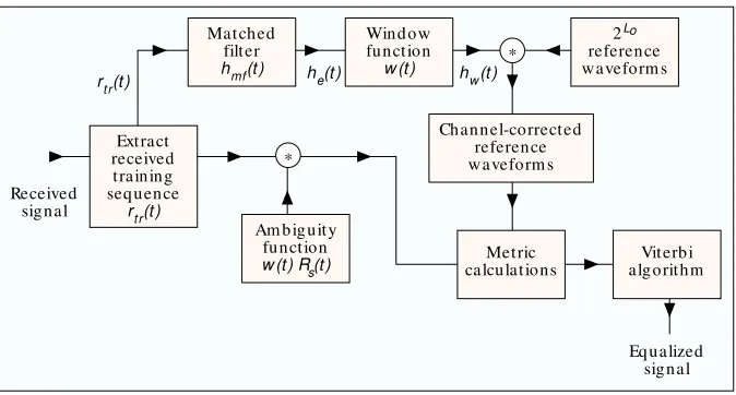
F igure 7 illustrates the basic functional blocks used in a G SM receiver for estimating the channel impulse response, which is then used to provide the detector with channel-correct-ed reference waveforms [27]. In the final step, the Viterbi algo-rithm is used to compute the MLSE of the message. A received signal can be described in terms of the transmitted signal con-volved with the impulse response of the channel. We show this below, using the notation of a received training sequence, rtr(t), and the transmitted training sequence, str(t), as follows:
rtr(t) = str(t) *hc(t) (12)
where * denotes convolution. At the receiver, rtr(t) is extracted
fr om t h e n or ma l bu r st a n d se n t t o a filt e r h a vin g impu lse response, hm f(t), that is matched to
str(t). This matched filter yields at its
output, an estimate of hc(t), denoted he(t), developed from E q. 12 as
fol-lows:
he(t) = rtr(t) *hm f(t)
= str(t) *hc(t) *hm f(t) (13)
= Rs(t) *hc(t)
wh e r e Rs(t) is t h e a u t o co r r e la t io n
function of str(t). If Rs(t) is a highly
peaked (impulse-like) function, then he(t) ≈ hc(t).
Next, using a windowing function, w(t), we truncate he(t) to form a
com-p u t a t io n a lly a ffo r d a b le fu n ct io n , hw(t) . T h e win d o w le n gt h m u st be
large enough to compensate for the effect of typical channel-induced ISI. The required observation interval Lo
for the window, can be expressed as
t h e su m o f t wo co n t r ib u t io n s. T h e interval of length LCISIis due to the
controlled ISI caused by G aussian fil-tering of the baseband pulses, which are then minimum shift keying (MSK) modulated. The interval of length LC
is d u e t o t h e ch a n n e l-in d u ce d I SI ca u se d b y m u lt ip a t h p r o p a ga t io n ; therefore, Locan be written as
Lo+ LCISI+ LC. (14)
The GSM system is required to pro-vide mitigation for distortion due to sig-nal dispersions of approximately 15–20 µs. The bit duration is 3.69 µs. Thus, the Viterbi equalizer used in GSM has a m e m o r y o f 4–6 b it in t e r va ls. F o r each Lo-bit interval in the message,
the function of the Viterbi equalizer is to find the most likely Lo-bit sequence out of the 2Lopossible sequences that might have been transmitted. D etermining the most likely Lo-bit
sequence requires that 2Lomeaningful reference waveforms
be created by modifying (or disturbing) the 2Loideal
wave-forms in the same way the channel has disturbed the transmit-t e d me ssa ge . T h e r e for e , transmit-t h e 2Lor e fe r e n ce wa ve for ms a r e
convolved with the windowed estimate of the channel impulse response, hw(t), in order to derive the disturbed or
channel-corrected reference waveforms. Next, the channel-channel-corrected reference waveforms are compared against the received data waveforms to yield metric calculations. H owever, before the comparison takes place, the received data waveforms are con-volved with the known windowed autocorrelation function w(t)Rs(t), transforming them in a manner comparable to that
applied to the reference waveforms. This filtered message sig-nal is compared to all possible 2Lochannel-corrected
refer-ence signals, and metrics are computed as required by the Viterbi decoding algorithm (VDA). The VDA yields the max-imum likelihood estimate of the transmitted sequence [6].
T
HE
R
AKE
R
ECEIVER
A
PPLIED TO
D
IRECT
-S
EQUENCE
S
PREAD
-S
PECTRUM
S
YSTEM S
I
nterim Specification 95 (IS-95) describes a D S/SS cellular system that uses a R ake receiver [7–9] to provide path diver-sity. In Fig. 8, five instances of chip transmissionscorrespond-■Figure 7.The Viterbi Equalizer as applied to GSM. Matched
filter hmf(t )
rt r(t ) he(t ) hw(t ) Wind ow function w (t )
2Lo reference waveform s
Viterb i algorithm
Eq ualized signal Received
signal
Metric calculations Channel-corrected
reference waveform s
Am b iguity function w (t ) Rs(t ) Extract
received training seq uence
rt r(t )
*
*
■Figure 8.An exam ple of received chips seen by a three-finger Rake receiver. Transm ission
tim e t
Transm itted cod e seq uence
Multip ath sp read
1 chip tim e 1
1
1
Delay tim e τ
Inp ut chip s to correlator # 1
Inp ut chip s to correlator # 2
Inp ut chip s to correlator # 3
t–4 0
1
τ1 τ2 τ3
t–3
1 chip tim e t–2
t–1
ing to the code sequence 1 0 1 1 1 are shown, with the trans-mission or observation times labeled t–4for the earliest
trans-m issio n a n d t0fo r t h e la t e st . E a ch a b scissa sh o ws t h r e e
“finge r s” of a signa l tha t a r r ive a t the r e ce ive r with de la y times τ1, τ2, and τ3. Assume that the intervals between the ti
t r a n smission t ime s a n d t h e in t e r va ls be t we e n t h e τid e la y
times are each one chip long. F rom this, one can conclude that the finger arriving at the receiver at time t–4, with delay
τ3, is time-coincident with two other fingers, namely the
fin-gers arriving at times t–3and t–2with delays τ2and τ1,
respec-tively. Since, in this example, the delayed components are separated by exactly one chip time, they are justresolvable. At the receiver, there must be a sounding device that is dedicated to estimating the τidelay times. Note that for a terrestrial
mobile radio system, the fading rate is relatively slow (mil-liseconds) or the channel coherence time large compared to the chip time (T0> Tch). H ence, the changes in τioccur
slow-ly enough that the receiver can readislow-ly adapt to them.
O nce the τidelays are estimated, a separate correlator is
dedicated to processing each finger. In this example, there would be three such dedicated correlators, each processing a delayed version of the same chip sequence, 1 0 1 1 1. In Fig. 8, each correlator receives chips with power profiles represented by the sequence of fingers shown along a diagonal line. Each correlator attempts to match these arriving chips with the same PN code, similarly delayed in time. At the end of a symbol interval (typically there may be hundreds or thousands of chips per symbol), the outputs of the correlators are coherently com-bined, and a symbol detection is made. At the chip level, the R ake receiver resembles an equalizer, but its real function is to provide diversity.
The inte r fe r e nce -suppr e ssion natur e of D S/SS syste ms st e m s fr o m t h e fa ct t h a t a co d e se q u e n ce a r r ivin g a t t h e r e ce ive r me r e ly on e ch ip t ime la t e , will be a ppr oxima t e ly orthogonal to the particular PN code with which the sequence is correlated. Therefore, any code chips that are delayed by one or more chip times will be suppressed by the correlator. The delayed chips only contribute to raising the noise floor (correlation sidelobes). The mitigation provided by the R ake receiver can be termed path diversity, since it allows the ener-gy of a chip that arrives via multiple paths to be combined coherently. Without the R ake receiver, this energy would be transparent and therefore lost to the DS/SS system. In Fig. 8, looking vertically above point τ3, it is clear that there is
inter-chip interference due to different fingers arriving simultane-ously. The spread-spectrum processing gain allows the system to endure such interference at the chip level. No other equal-ization is deemed necessary in IS-95.
S
UM M ARY
I
n Part II of this article, the mathematical model and the major elements that contribute to fading in a communica-tion channel have been briefly reviewed (from Part I of the tutorial). Next, mitigation techniques for ameliorating the effects of each degradation category were treated, and sum-marized in Fig. 5. Finally, mitigation methods that have been implemented in two system types, G SM and CD MA systems meeting IS-95, were described.R
EFERENCES[1 ] T. S. Ra p p a p o rt , Wireless Co m m u n icat io n s, Up p e r Sa d d le Rive r, NJ: Prentice Hall, 1996.
[2] J. G. Proakis, Digital Communications, Ch. 7, New York: McGraw-Hill, 1983. [3 ] R. L. Bo g u sch , F. W. Gu ig lia n o , a n d D. L. Kn ep p , “Freq u en cy- Select ive Scintillation Effects and Decision Feedback Equalization in High Data-Rate Satellite Links,” Proc. IEEE, vol. 71, no. 6, June 1983, pp. 754–67.
[4 ] S. U. H. Qu re sh i, “Ad a p t ive Eq u a liza t io n ,” Proc. IEEE, vo l. 7 3 , n o . 9 , Sep t. 1985, p p . 1340–87.
[5 ] G. D. Fo rn e y, “Th e Vit e rb i Alg o rit h m ,” Proc. IEEE, vo l. 6 1 , n o . 3 , Ma r. 1978, p p . 268–78.
[6] B. Sklar, Digit al Communicat ions: Fundament als and Applicat ions, Ch. 6, Englewood Cliffs, NJ: Prentice Hall, 1988.
[7] R. Price and P. E. Green, Jr., “A Communication Technique for Multipath Chan-nels,” Proc. IRE, vol. 46, no. 3, Mar. 1958, pp. 555–70.
[8] G. L. Turin, “Introd uction to Sp read -Sp ectrum Antim ultip ath Techniq ues and Their Ap p lication to Urb an Dig ital Rad io,” Proc. IEEE, vol. 68, no. 3, Mar. 1980, pp. 328–53.
[9] M. K. Sim on et al.,Spread Spectrum Communications Handbook, McGraw Hill, 1994.
[10] F. Am o ro so , “Use o f DS/SS Sig n a lin g t o Mit ig a t e Ra yleig h Fa d in g in a Den se Sca t t erer En viro n m en t ,” IEEE Pers. Commun., vo l. 3, n o . 2, Ap r. 1996, p p . 52–61.
[11] M. A. Birch ler a n d S. C. Ja sp er, “A 64 kb p s Dig it a l La n d Mo b ile Ra d io System Em p loying M-16QAM,” Proc. 1992 IEEE Int ’l. Conf. Sel. Topics in Wireless Commun., Vancouver, Canad a, June 25–26, 1992, p p . 158–62. [12] H. Sari, G. Karam , and I. Jeanclaude, “Transm ission Techniques for Digital
Te rre st ria l TV Bro a d ca st in g ,” IEEE Commun. M ag., vo l. 3 3 , n o . 2 , Fe b . 1995, pp. 100–109.
[13] J. K. Cavers, “The Performance of Phase Locked Transparent Tone-in-Band with Symmetric Phase Detection,” IEEE Trans. Commun., vol. 39, no. 9, Sept. 1991, pp. 1389–99.
[14] M. L. Moher and J. H. Lodge, “TCMP — A Modulation and Coding Strategy for Rician Fading Channel,” IEEE JSAC, vol. 7, no. 9, Dec. 1989, pp. 1347–55. [15] R. L. Bogusch, Digit al Communicat ions in Fading Channels: M odulat ion
and Coding, Missio n Research Co rp ., San ta Barb ara, CA, Rep . n o . MRC-R-1043, Mar. 11, 1987.
[16] F. Harris, “On th e Relatio n sh ip Betw een Mu ltirate Po lyp h ase FIR Filters a n d Win d o w ed , Overla p p ed FFT Pro cessin g ,” Proc. 23rd Annual Asilo-mar Conf . Signals, Sys., and Comp., Pa cific Gro ve, CA, Oct . 30–No v. 1, 1989, p p . 485–88.
[1 7 ] R. W. Lo w d e rm ilk a n d F. Ha rris, “De sig n a n d Pe rfo rm a n ce o f Fa d in g In sen sit ive Ort h o g o n a l Freq u en cy Divisio n Mu lt ip lexin g (OFDM) Usin g Po lyp h a se Filt erin g Tech n iq u es,” Proc. 30t h Annual Asilomar Conf . Sig-nals, Sys., and Comp., Pacific Grove, CA, Nov. 3–6, 1996.
[18] M. Kavehrad and G. E. Bod eep , “Desig n and Exp erim ental Results for a Direct -Seq u en ce Sp rea d -Sp ect ru m Ra d io Usin g Differen t ia l Ph a se-Sh ift Ke yin g Mo d u la t io n fo r In d o o r Wire le ss Co m m u n ica t io n s,” IEEE JSAC, vol. SAC-5, no. 5, June 1987, p p . 815–23.
[1 9 ] G. C. He ss, Land-M ob ile Radio Syst em Engineering, Bo st o n : Art e ch House, 1993.
[20] J. Hag enauer and E. Lutz, “Forw ard Error Correction Cod ing for Fad ing Co m p en sa t io n in Mo b ile Sa t ellit e Ch a n n els,” IEEE JSAC, vo l. SAC-5, n o . 2, Feb . 1987, p p . 215–25.
[21] P. I. McLane, et . al., “PSK and DPSK Trellis Cod es for Fast Fad ing, Shad -owed Mob ile Satellite Com m unication Channels,” IEEE Trans. Commun., vol. 36, no. 11, Nov. 1988, p p . 1242–46.
[2 2 ] C. Sch le g e l, a n d D. J. Co st e llo , Jr., “Ba n d w id t h Efficie n t Co d in g fo r Fa d in g Ch a n n e ls: Co d e Co n st ru ct io n a n d Pe rfo rm a n ce An a lysis,” IEEE JSAC, vol. 7, no. 9, Dec. 1989, p p . 1356–68.
[2 3 ] F. Ed b a u er, “Perfo rm a n ce o f In t erlea ved TrellisCo d ed Differen t ia l 8 -PSK Mo d u la t io n o ve r Fa d in g Ch a n n e ls,” IEEE JSAC, vo l. 7 , n o . 9 , De c. 1989, p p . 1340–46.
[24] S. So lim a n a n d K Mo kra n i, “Perfo rm a n ce o f Co d ed Syst em s o ver Fa d-in g Disp e rsive Ch a n n e ls,” IEEE Tran s. Co m m u n ., vo l. 4 0 , n o . 1 , Ja n . 1992, p p . 51–59
[2 5 ] D. Divsa la r a n d F. Po lla ra , “Tu rb o Co d es fo r PCS Ap p lica t io n s,” Proc. ICC ’95, Seattle, WA, June 18–22, 1995, p p . 54–59.
[26] A. J. Batem an and J. P. McGeehan, “Data Transm ission over UHF Fad ing Mobile Radio Channels,” IEE Proc., vol. 131, pt. F, no. 4, July 1984, pp. 364–74. [2 7 ] L. Ha n zo a n d J. St e fa n o v, “Th e Pa n -Eu ro p e a n Dig it a l Ce llu la r Mo b ile Ra d io Syst e m — Kn o w n a s GSM,” M ob ile Radio Commun., R. St e e le , Ed ., Ch. 8, Lond on: Pentech Press, 1992.
B
IOGRAPHY