Prosiding Seminar Nasional Sains dan Teknologi 2010
SURFACE TOPOGRAPHICAL CHANGE DUE TO SLIDING CONTACT
Jamari1), E. Saputra1), R. Ismail2), M. Taviqirrahman2) and D.J. Schipper3) 1) Graduate Program in Mechanical Engineering, University of Diponegoro
Jl. Prof. Soedarto SH, Tembalang, Semarang 50275 Indonesia, Telp/Fax: +62 24 7460059,
2) Laboratory for Surface Technology and Tribology, Faculty of Engineering Technology
University of Twente, Drienerloolaan 5, Postbus 217, 7500 AE Enschede, The Netherlands
E-mail: [email protected]
Abstract
Many engineering applications often involve contacting surfaces. The contact can be either in the form of sliding, rolling or a combination of sliding and rolling. Sliding contact between mechanical components such as gears and cam and followers will result in wear. Wear is caused by mechanical or chemical interactions, and is a highly complex phenomenon. The mechanical engineers who faced the immediate problem of wear control in machinery had however to respond to the situation by formulating first order models based on purely mechanical concepts. This paper presents a model to predict the change of surface topography due to sliding contact or wear. The surface topography is represented by an asperity. The general Archard’s wear equation is employed in combination with finite element analysis for constructing the model. The development of contact pressure distribution and geometrical change are investigated as a function of sliding distance. Results show that for the same contact condition the wear depth of the asperity is affected dominantly by the sliding distance. Keywords: asperity, sliding contact, wear, elastic-plastic contact, finite element analysis.
Introduction
Many engineering applications often involve contacting surfaces. To study the interacting surfaces needs Tribology. Tribology is the science and technology of interacting surfaces in relative motion, and includes the study of friction, wear and lubrication. An account of the long history of tribology has been presented by Dowson (1998). The very early studies of tribology were concerned with friction, since this was perceived to be the major problem to be overcome in transporting heavy objects on sledges. The major imperatives driving studies of tribology in the late nineteenth century were the problems being experienced on the rapidly developing railways and the production of mineral oil. These industrial developments promoted the golden decade of tribological engineering science in the 1880s. By the end of the nineteenth century major bearing companies were being formed and the oil industry was established.
Sliding is a very old problem in engineering. Sliding contact between mechanical components such as gears and cam and followers will result in wear. In many applications wear is avoided. To minimize wear it is crucial to understand why the wear occurs. Rom such an understanding can emerge predictive models which can help in designing a component and selecting the material for minimizing the loss of material by wear. Wear is a highly complex phenomenon. The character of a surface is determined by the bulk chemical and physical structure as well as environmental condition (Biswas, 1997). The topography is determined by the method of manufacture. The complexity of the phenomenon inhibited any comprehensive modeling for a long time. The mechanical engineers who faced the immediate problem of wear control in machinery had however to respond to the situation by formulating first order models based on purely mechanical concepts. It was recognized in the early nineteen fifties that when metals wear out asperities are involved in this interaction and large strains are incurred at the asperity level or below the asperity root which, in case of metals at least take the material well past the yield point. The first models of adhesive and abrasive wear thus invoked asperity contact and considered the soft asperity or substrate to undergo plastic flow.
D.8. Surface Topographical Change Due To Sliding Contact... (Jamari)
classified into two main categories, (i) mechanistic models, which are based on material failure mechanism, e.g., ratcheting theory for wear (Kapoor and Johnson, 1994) and (ii) phenomenological models, which often involve quantities that have to be computed using principles of contact mechanics, e.g., wear model of Archard (1953). Archard-based wear model have been studied extensively by combining with numerical calculation such as finite element analysis. Podra and Andersson (1999) simulated sliding wear of a pin-on-disc with finite element method. Numerical simulations of wear of a cylindrical steel roller oscillating against a steel was also performed by Oqvist (2001) with a special version of finite element program. The simulation was done in steps and the pressure and the sliding distance was recalculated as the surface geometry changed. Similar to Oqvist, Hegadekatte et al. (2006, 2008) proposed a modeling scheme for wear in tribometers. The model was claimed to be very efficient. Recently, Mukras et al. (2009) introduced a wear prediction model for an oscillatory conforming contact. The model was build upon the same iterative wear prediction procedure. This paper presents the similar numerical procedure for wear prediction in sliding contact. The topographical change of the asperity is represented by the wear depth of the asperity as a function of the sliding distance. The main purpose of the present work is to further investigate the validity of the reported model in the literature.
Surface Topographycal Change
When two surfaces are loaded for the first time and moved relatively to one another, changes in the condition of both surfaces generally occur. These changes are usually a combination of many things. All these changes are adjustments to minimize energy flow, whether mechanical or chemical, between the moving surfaces. The changes which occur between start-up and steady state are associated with running-in, also called breaking-in or wearing-in, (Jamari, 2006). Running-in is an effective way of matching two contacting components in a functional situation of rolling and/or sliding. There are many parameter changes during running-in, chemically or mechanically. However, the change of the micro-geometry due to wear or plastic deformation is dominant.
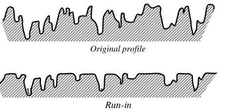
Figure 1: Effect of running-in on the surface profile.
Two historical terms are particularly associated with running-in: asperity truncation and elastic shakedown. In asperity truncation, most studies have been done on modeling the surface statistically. The shape change of the amplitude distribution curve after the running-in has taken place is shown in Fig. 1. One would expect the change of the statistical surface parameters such as average roughness, root-mean-square roughness, peak-to-valley height, slope, etc. during running-in. However, the change of the surface topography is in fact not only the height distribution (one dimension) but change in three dimensions in order to conform to each other. In most of the contacting engineering surfaces, the coefficient of friction and wear are decreased due to the running-in process. Plastic deformation leads to the increase of the contacting area and as a result, the mean contact pressure decreases or the load carrying capacity is increased. It is worth noting that if the plastic deformation occurs macroscopically, the change of the roller diameter in roller bearing for instance, there will be a failure of functionality. But if the plastic deformation occurs microscopically, i.e. on roughness level, the functionality performance of the machine components will be increased.
Original profile
Run-in
Modeling Procedure
operating cycles have to be simulated. Under these circumstances, a finite element post-processor is the most logical choice considering the magnitude of the computational expense of such large-scale contact simulations. Also, the simulation does not aim to simulate the entire sliding process of a contact system with dynamic finite element analysis but instead treats the problem of sliding wear as ‘quasi-static’ in order to save on the computational expense. Therefore, to be as realistic as possible, a general contact problem involving two deformable bodies is solved by a number of times at different stages (wear steps) of the sliding process with the surface evolving through different wear steps.
Yes
• Local Wear Model (Archard’s Law)
• Wear Depth
• Wear-Progress Direction Surface Normal Pressure
(Contact Pressure)
Updated geometry
•Wear Depth as Boundary Cond.
•Extract Node Coordinates.
FEM Simulation
•Geometry
•Contact Defn.
•Material Model
•Boundary Cond.
END
No
s ≥ smax?
START
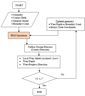
Figure 2: Flowchart of the numerical wear simulation.
Figure 2 shows the entire process of the wear simulation procedure. This model was adapted from the work of Hegadekatte et al. (2008). The inputs are geometry, contact definition, material model and boundary condition. The wear process simulation begins with the finite element solution of the contact problem. The surface normal pressure or contact pressure distribution will be calculated on the element topology for the 3D geometry. The contact pressure at each of the surface nodes then will be used for calculating local wear by Archard’s law. Here, the wear depth of the contacting system is determined from the combination of the finite element calculated contact pressure and Archard’s model where the sliding distance s is incorporated. After the first step of wear the geometry of the contact system is updated with the amount of the calculated wear. In this process, the nodes and all other contact boundary conditions are updated. The size of the wear step (the amount of sliding performed in each wear step) directly affects the accuracy of the
D.8. Surface Topographical Change Due To Sliding Contact... (Jamari)
wear processing. The larger the size of the wear step, the larger will be the error and vice versa, owing to the considerable variation in the contact condition (contact area and the contact pressure field). On the other hand, the finer the size of the wear step, the higher will be the number of contact simulations required, which forms the bottleneck as far as the computation time is concerned. If the sliding distance is progressing, the aforementioned routine is repeated until a certain defined distance is achieved.
(a) (b)
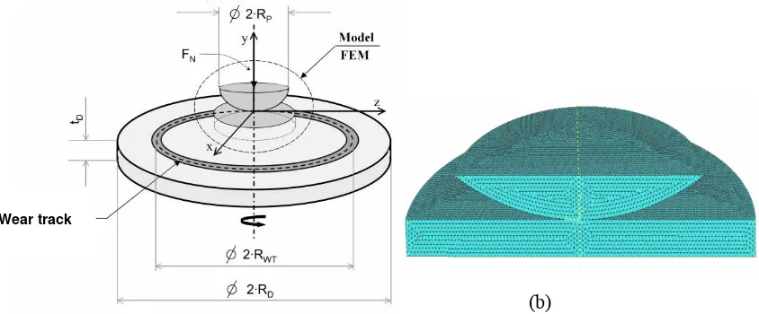
Figure 3: Pin-on-disc contact system (a) and its finite element model (b).
Wear track
In the present study, a pin-on-disc contact sliding contact system is simulated for the wear prediction. A pin radius RP of 0.794 mm in contact with a disc of RD = 4 mm was slide against each
other in a wear track RWT = 3 mm. The thickness of the disc tD is 1 mm and the load FN of 200 mN
was applied, see Fig. 3(a). The material property used for pin and disc in the present study was ceramic Si3N4 with the modulus elasticity E = 304 GPa, the Poisson’s ratio v = 0.24 and the coefficient of friction
μ
= 0.45. The finite element model of the contact system is presented in Fig. 3(b).Results and Discussions
(a)
(b)
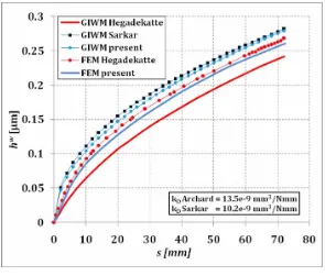
Figure 4: Wear depth of pin as a function of the sliding distance (a) and the pressure development of pin as a function of the sliding distance (b).
Conclussion
A finite element based numerical simulation was carried out to explore the development of surface geomterical change due to sliding contact. The sliding contact of a pin-on-disc system was used to represent the asperity interaction of the rough surface contact. The results were compared with the similar model available in literature.
The results of the present study showed good agreement with the prediction of other models. It can be concluded that the developed wear model can be used to simulate wear on a rough surface contact or in a global scale. For the pressure distribution, the present model predicts the behaviour better than other model.
D.8. Surface Topographical Change Due To Sliding Contact... (Jamari)
References
ABAQUS/Standard 6.5, 2003, Example Problems Manual 3.1.8., Hibbit, Karlsson & Sorensen Inc., USA.
Archard, J.F.,1953, Contact and rubbing of flat surfaces, Journal of Applied Physics, 24, pp. 981-988.
Biswas, S.K., 1997, New Directions in Tribology, Mechanical Engineering Publication, London. Dowson, D., 1998, History of Tribology, Second edition, Professional Engineering Publishing,
London.
Hegadekatte, V., Huber, N. and Kraft, O., 2006, Finite element based simulation of dry sliding wear, Tribology Letters, 24, pp. 51-60.
Hegadekatte, V., Kurzenhauser, S., Huber, N. and Kraft, O., 2008, A predictive modeling scheme for wear in tribometers, Tribology International, 41, pp. 1020-1031.
Jamari, 2006, Running-in of Rolling Contacts, PhD Thesis, Unversity of Twente, Enschede, The Ntherlands.
Kapoor, A., Johnson, K.L., 1994, Plastic ratcheting as a mechanism of metallic wear, Proc. R. Soc.
London A, 445, pp. 367-381.
Mukras, S., Kim, N.H., Sawyer, W.G., Jackson, D.B. and Bergquist, L.W., 2009, Numerical integration schemes and parallel computation for wear prediction using finite element method, Wear, 266, pp. 822-831.
Oqvist, M., 2001, Numerical simulations of mild wear using updated geometry with different step size approaches, Wear, 249, pp. 6-11.
Podra, P., 1997, FE Wear Simulation of Sliding Contacts, PhD thesis, Royal Institute of Technology (KTH), Stockholm, Sweden.
Podra, P. and Andersson, S., 1999, Simulating sliding wear with finite element method, Tribology
International, 32, pp. 71-81.
Saputra, E., 2010, Perhitungan Keausan Pin pada Sistem Kontak Sliding Pin-on-disc
Menggunakan Metode Analitik dan Metode Elemen Hingga, Bachelor Thesis, Unversity of
Diponegoro, Semarang, Indonesia.