DATA PROCESSING AND ANALYSIS TOOLS BASED ON
GROUND-BASED SYNTHETIC APERTURE RADAR IMAGERY
M. Crosetto*, O. Monserrat, G. Luzi, N. Devanthéry, M. Cuevas-González, A. Barra
Centre Tecnològic de Telecomunicacions de Catalunya (CTTC/CERCA), Division of Geomatics, Av. Gauss 7, E-08860, Castelldefels (Barcelona), Spain - (mcrosetto, omonserrat, gluzi, ndevanthery, mcuevas, abarra)@cttc.cat
Commission III, WG III/3
KEY WORDS: SAR, interferometry, deformation monitoring, deformation analysis.
ABSTRACT:
The Ground-Based SAR (GBSAR) is a terrestrial remote sensing technique used to measure and monitor deformation. In this paper we describe two complementary approaches to derive deformation measurements using GBSAR data. The first approach is based on radar interferometry, while the second one exploits the GBSAR amplitude. In this paper we consider the so-called discontinuous GBSAR acquisition mode. The interferometric process is not always straightforward: it requires appropriate data processing and analysis tools. One of the main critical steps is phase unwrapping, which can critically affect the deformation measurements. In this paper we describe the procedure used at the CTTC to process and analyse discontinuous GBSAR data. In the second part of the paper we describe the approach based on GBSAR amplitude images and an image-matching method.
* Corresponding author
1. INTRODUCTION
Ground-Based SAR (GBSAR) interferometry is a radar-based terrestrial remote sensing technique that can be used to generate digital elevation models or to measure and monitor deformation. In this paper we consider the deformation monitoring application, which is by far the more important one. For a general GBSAR review refer to Monserrat et al. (2014). GBSAR deformation monitoring can be performed using two types of acquisition modes: the continuous (C-GBSAR) and the discontinuous (D-GBSAR) ones.
In the C-GBSAR, the radar is installed permanently close to the area of interest, acquiring data periodically, with a period that can be as short as a few minutes, if needed. This is the most commonly used configuration, which is suitable to carry out near real-time deformation monitoring, e.g. see Casagli et al. (2003) and Tarchi et al. (2003). This configuration offers the best GBSAR performances in terms of measurement density (this is related to the high coherence of the C-GBSAR data), precision and robustness. Some C-GBSAR applications described in the literature include: slope monitoring in open pit mines (Noon et al., 2007; Farina et al., 2012); slope instability monitoring related to rockslides (Tarchi et al., 2005), landslides (Barla et al., 2010) or volcanoes (Casagli et al. 2010); urban monitoring (Pipia et al., 2013); structure monitoring (Tarchi et al., 1997); dam monitoring (Tarchi et al., 1999); dike monitoring (Monserrat, 2012); glacier monitoring (Noferini et al., 2009); etc.
In the D-GBSAR, the radar is installed and dismounted at each acquisition campaign, revisiting a given site periodically, e.g. monthly, yearly, etc. The revisiting time depends on the cinematics of the deformation phenomenon at hand and on the specific requirements of the monitoring at study. This configuration is appropriate to monitor slow deformation
phenomena, where the continuous acquisition is usually unnecessary. It is worth noting that this is the same configuration usually adopted by many other deformation monitoring techniques. The main advantage of D-GBSAR is the reduced monitoring cost by sharing the same instrument over several sites. Its drawbacks include a more complex data processing and, compared with C-GBSAR, a reduced density, precision and reliability of deformation measurements. The standard GBSAR acquisition mode is C-GBSAR: in the literature there are only a few works that describe D-GBSAR applications, e.g. see Noferini et al. (2008) and Wujanz et al. (2013). Crosetto et al. (2014a) describe different D-GBSAR case studies.
This paper is focused on the D-GBSAR acquisition mode. It describes two approaches to derive deformation measurements using GBSAR data: the GBSAR interferometry and the GBSAR-amplitude image matching.
2. GBSAR INTERFEROMETRY
This section briefly discusses the GBSAR interferometry procedure implemented by the authors. This procedure shares common processing tools with the procedure used to analyse satellite-based SAR interferometric data, e.g. see Crosetto et al., (2011). The main steps of the procedure are concisely discussed below. A detailed description and discussion of the procedure can be found in Monserrat (2012), Monserrat et al. (2014) and Crosetto et al. (2014a).
The procedure starts with the acquisition of N sets of images, typically coming from N different campaigns, i.e. by visiting the same site N times. The images of each campaign are firstly focused. Usually, the images of each campaign are coherently averaged. The resulting images are then co-registered, usually taking the geometry of the first campaign as reference image.
The International Archives of the Photogrammetry, Remote Sensing and Spatial Information Sciences, Volume XLII-2/W7, 2017 ISPRS Geospatial Week 2017, 18–22 September 2017, Wuhan, China
This contribution has been peer-reviewed.
This step is followed by the generation of N-1 interferograms and the associated coherence images.
Using the coherence images or, alternatively, the so-called Dispersion of Amplitude (the ratio between the standard deviation and the mean of image amplitudes), a pixel selection is performed, which aims at separating the pixels that contain useful information from those that are dominated by noise. A spatial phase unwrapping is performed on the selected pixels (i.e. on an irregular set of points) for the N-1 interferograms. We use in this step an implementation of the Minimum Cost Flow method proposed by Costantini (1998). The phase unwrapping is one of the most critical steps of the entire procedure.
The resulting phases are temporally integrated to obtain a set of phases, which are temporally ordered, in correspondence of the N acquisition campaigns. This is done by setting to zero the phases in correspondence of the first campaign. An Atmospheric Phase Screen (APS) estimation follows, which makes use of known stable areas located in the surrounding of the observed scene. The geometry and distribution of these stable areas strongly influences the quality of the APS estimates. The APS component is then subtracted from the image phases. The APS-cleaned phases are then converted in Line-Of-Sight (LOS) displacements. Finally, the data are geocoded, obtaining the two main GBSAR products: the geocoded accumulated deformation maps and the geocoded deformation time series.
2.1 Example of GBSAR interferometry application
We describe in this section the D-GBSAR deformation monitoring of the village of Barberà de la Conca, located in Southern Catalonia (Spain). This village has experienced deformations since 2011 that have caused cracks in the church and several surrounding buildings. Four D-GBSAR campaigns are considered in this work: 14 November 2011, 19 December 2011, 8 May 2012 and 20 March 2013.
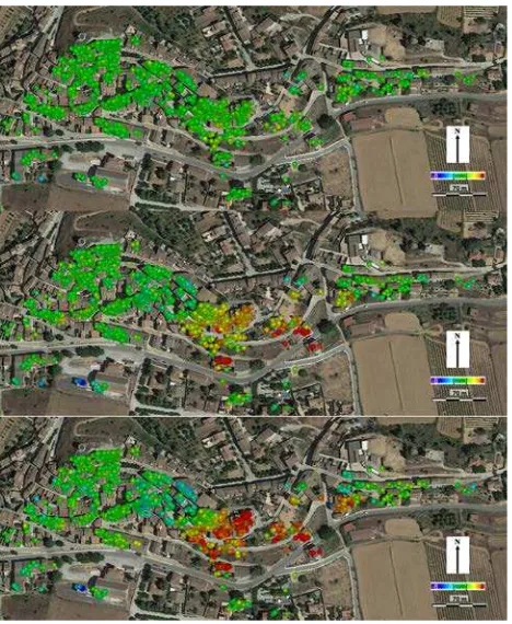
The campaigns cover a total observation period of about 16 months. The village was monitored using a Ku-band GBSAR, the IBIS-L by IDS Spa (www.idscorporation.com). The radar was installed outside the village at an average distance of 0.5 km. A picture of the observed scene is shown in Figure 1. The data analysis was based on 10 SAR images acquired in each campaign, from which four coherently averaged images were derived. After the second campaign, the measurement density achievable over the area of interest was checked. As it can be observed in Figure 2, over the observed scene there is a dense set of measurements, which cover a great number of buildings and structures. This proves the feasibility of D-GBSAR monitoring without deploying corner reflectors. A key additional characteristic of this area is the favourable geometry to estimate the APS: the deformation area is surrounded by stable areas.
Between the first two campaigns, the displacements are imperceptible. However, from the third campaign they are clearly visible. They include two main deformation areas characterized by opposite slope aspects. The area in yellow to red colours, which indicate deformation toward the radar up to 14.6 mm, and the area in light blue to blue colours, which indicates deformation values away from the radar up to -8.9 mm. This result proved to be essential to understand the deformation mechanism of this area.
Figure 1. Picture of Barberà de la Conca (Spain) seen from the GBSAR viewpoint.
Figure 2. Displacement maps of Barberà de la Conca (Spain) between November 2011 and December 2011 (above), between
November 20111 and May 2012 (middle) and between November 2011 and March 2013 (below).
3. GBSAR-AMPLITUDE IMAGE MATCHING
GBSAR interferometry suffers important limitations. First of all, it requires that a sufficient number of targets remain coherent over the observation period. A second limitation of phase unwrapping is aliasing. In fact, due to the ambiguous nature of the interferometric phases, the displacements can only unambiguously be estimated if the relative displacements actually occurring between adjacent coherent targets originate an interferometric phase difference that is smaller than π. The atmospheric phase component is a third important limitation
The International Archives of the Photogrammetry, Remote Sensing and Spatial Information Sciences, Volume XLII-2/W7, 2017 ISPRS Geospatial Week 2017, 18–22 September 2017, Wuhan, China
This contribution has been peer-reviewed.
that may degrade the quality of the estimation. The forth limitation is the mono-dimensional nature of the GB-InSAR measurements.
The GBSAR-amplitude image matching described below can potentially overcome the above limitations. The procedure uses an image matching technique applied on amplitude GB-SAR images using special targets. The easiest way to have such targets is to use artificial Corner Reflectors (CRs). The procedure employs a GB-SAR in a discontinuous mode, it uses an image matching procedure and deploys CRs. A complete description of the proposed procedure is described in Crosetto et al. (2014b). The main steps of the proposed procedure are briefly described below.
Data acquisition is obtained through a series of N in-situ campaigns. Each campaign consists of installing the GB-SAR instrument, deploying a set of M CRs and acquiring K complex SAR images. For each campaign, an incoherent temporal averaging of the K images is performed. A global image matching is performed using data coming from consecutive campaigns. It involves a pixel selection to identify suitable pixels for image matching. The global image matching, which is performed over the set of selected pixels, generate a set of global image shifts. We use an incoherent cross-correlation based on the amplitude images (see Figure 3). The GB-SAR repositioning effects are then estimated, which are due to small changes in the position and orientation of the GB-SAR that can occur between different campaigns. This involves the selection of stable areas in the area in the observed scene. Using the stable areas, the co-registration transformation parameters are computed for each pair of campaigns. The estimation of the displacements is then performed on each pair campaigns by subtracting the GB-SAR-repositioning effects from the set of pairs of global shifts. The obtained displacement shifts that are relative to the whole set of stable areas mentioned above. The above displacement shifts are then transformed into displacements. A data geocoding follows.
3.1 Example of application
We briefly describe in this section the results of some validation experiments of the GBSAR-amplitude image matching. The experiments were carried out using an IBIS-L Ku-band GB-SAR, using a pixel spacing in range of 0.5 m and a cross-range angular spacing of 4.4 mrad. Three experiments are described below: the Beach experiment was performed using CRs of different sizes located at different ranges; the Cal Ganxo experiment involved CRs located at far distances; and the final experiment was carried out at the Vallcebre landslide. Two types of validation data were collected: (i) artificially-induced deformations were obtained by imposing known displacements to a set of CRs in the first two experiments; (ii) in the last one, independent ground truth was collected using an electronic distance meter.
The validation results are summarized in Table 1. In the Beach experiment, six of the eight CRs with Peak-to-Background Ratio (PBR) above 30 dB have validation errors below 1 cm. In the Cal Ganxo experiment, the four CRs with high PBR have validation errors below 1 cm. Note that all of them were located at more than 1550 m from the GB-SAR. By contrast, the three CRs with PBR below 30 dB show large errors. This result confirms that the PBR of a given target is strongly influencing the matching performances, and hence the goodness of the estimated deformations.
Figure 3: example of GBSAR amplitude image.
Table 1: results of the GBSAR-amplitude image matching validations.
The International Archives of the Photogrammetry, Remote Sensing and Spatial Information Sciences, Volume XLII-2/W7, 2017 ISPRS Geospatial Week 2017, 18–22 September 2017, Wuhan, China
This contribution has been peer-reviewed.
In the Vallcebre landslide, all the 12 CRs, ranging from 507 to 832 m and with high PBR (mean PBR = 34 dB), show validation errors below 1 cm. It is worth noting that these values include the topographic measurement uncertainty. They are very encouraging from both the point of view of image matching (0.59 cm corresponds to 1/85th of the pixel size) and the deformation measurement.
The results shown in Table 1 are encouraging. They are far from the millimetre-level precision of GBSAR interferometry. In addition, they require special targets, optimal for image matching purposes, which can be obtained by using artificial CRs. However, they offer interesting advantages. It provides non-ambiguous, aliasing-free, displacement estimates. The displacement estimates are not affected by atmospheric effects. Finally, it provides 2D displacement measurements, in range and cross-range directions, which represent an improvement with respect to the line-of-sight estimates generated by SAR interferometry. It is worth noting that the precision in cross-range is worse than the precision in cross-range, see for details Crosetto et al. (2014b). The PBR is the main parameter that drives the precision of the deformation estimates.
REFERENCES
Barla, G., Antolini, F., Barla, M., Mensi, E., Piovano, G., 2010. Monitoring of the Beauregard landslide (Aosta Valley, Italy) using advanced and conventional techniques. Engineering
Geology, 116, pp. 218-235.
Casagli, N., Farina, P., Leva, D., Nico, G., Tarchi, D., 2003. Ground-based SAR interferometry as a tool for landslide monitoring during emergencies. In: Proc. of IGARSS 2003, Vol. 4, pp. 2924-2926.
Casagli, N., Catani, F., Del Ventisette, C., Luzi, G., 2010. Monitoring, prediction, and early warning using ground-based radar interferometry. Landslides, 7(3), pp. 291–301.
Costantini, M., 1998. A novel phase unwrapping method based on network programming. IEEE Transactions on Geoscience
and Remote Sensing, 36(3), pp. 813-821.
Crosetto, M., Monserrat, O., Cuevas, M. and Crippa, B., 2011. Spaceborne Differential SAR Interferometry: Data Analysis Tools for Deformation Measurement. Remote Sensing, 3, pp. 305-318.
Crosetto, M., Monserrat, O., Luzi, G., Cuevas-González, M., Devanthéry, N., 2014a. Discontinuous GBSAR deformation monitoring. ISPRS Journal of Photogrammetry and Remote
Sensing. 93, pp. 136-141.
Crosetto, M., Monserrat, O., Luzi, G., Cuevas, M., and Devanthéry, N., 2014b. A Noninterferometric Procedure for Deformation Measurement Using GB-SAR Imagery. IEEE
Geoscience and Remote Sensing Letters, 11(1), pp. 34-38.
Farina, P., Leoni, L., Babboni, F., Coppi, F., Mayer, L., Coli, N., Thompson, C., 2012. Monitoring engineered and natural slopes by ground-based radar: methodology, data processing and case studies review. In: Proc. of SHIRMS 2012, May 15-17, 2012 Sun City, South Africa.
Monserrat, O., 2012. Deformation measurement and
monitoring with Ground-Based SAR. PhD thesis, Technical
University of Catalonia, available on-line at www.cttc.es.
Monserrat, O., Crosetto, M., Luzi, G., 2014. A review of ground-based SAR interferometry for deformation measurement. ISPRS Journal of Photogrammetry and Remote
Sensing, 93, pp. 40–48.
Noferini, L., Takayama, T., Mecatti, D., Macaluso, G., Luzi, G., Atzeni, C., 2008. Analysis of Ground-Based SAR data with diverse temporal baselines. IEEE Transactions on Geoscience
and Remote Sensing, 46(6), pp. 1614-1623.
Noferini, L., Mecatti, D., Macaluso, G., Pieraccini, M., & Atzeni, C., 2009. Monitoring of Belvedere Glacier using a wide angle GB-SAR interferometer. Journal of Applied Geophysics, 68(2), pp. 289-293.
Noon, D., Harries, N., 2007. Slope Stability Radar for Managing Rock Fall Risks in Open Cut Mines. In: Proc. of
Large Open Pit Mining Conference, Perth, WA, 10-11
September 2007.
Pipia, L., Fabregas, X., Aguasca, A., Lopez-Martinez, C., 2013. Polarimetric Temporal Analysis of Urban Environments With a Ground-Based SAR. IEEE Transactions on Geoscience and
Remote Sensing, 51(4), pp. 2343-2360.
Tarchi, D., Ohlmer, E., Sieber, A.J., 1997. Monitoring of structural changes by radar interferometry. Journal of Research
in Nondestructive Evaluation, 9(4), pp. 213-225.
Tarchi, D., Rudolf, H., Luzi, G., Chiarantini, L., Coppo, P., Sieber, A.J., 1999. SAR interferometry for structural changes detection: A demonstration test on a dam. In: Proc. of IGARSS 1999, Hamburg, Germany, pp. 1522–1524.
Tarchi, D., Casagli, N., Fanti, R., Leva, D., Luzi, G., Pasuto, A., Pieraccini, M., Silvano, S., 2003. Landslide monitoring by using ground-based SAR interferometry: an example of application. Engineering Geology, 68(1-2), pp. 15-30.
Tarchi, D., Antonello, G., Casagli, N., Farina, P., Fortuny-Guasch, J., Guerri, L., Leva, D., 2005. On the Use of Ground-Based SAR Interferometry for Slope Failure Early Warning: the Cortenova Rock Slide (Italy). Landslides: Risk Analysis and Sustainable Disaster Management, In: Proc. of the 1st General
Assembly of the Int. Consortium on Landslides, Sassa, K. et al.
(Eds.), Springer-Verlag, Berlin, Heidelberg.
Wujanz, D., Neitzel, F., Hebel, H.P., Linke, J., Busch, W. 2013. Terrestrial radar and laser scanning for deformation monitoring: first steps towards assisted radar scanning. ISPRS Annals, Volume II-5/W2, ISPRS Workshop Laser Scanning 2013, 11– 13 November 2013, Antalya, Turkey.
The International Archives of the Photogrammetry, Remote Sensing and Spatial Information Sciences, Volume XLII-2/W7, 2017 ISPRS Geospatial Week 2017, 18–22 September 2017, Wuhan, China
This contribution has been peer-reviewed.