ANISOTROPIC SCATTERING SHADOW COMPENSATION METHOD FOR REMOTE
SENSING IMAGE WITH CONSIDERATION OF TERRAIN
Qiongjie Wang a, Li Yan a, *
a School of Geodesy and Geomatics, Wuhan University, 129 Luoyu Road, Wuhan, China
[email protected], [email protected]
Commission I, WG I/4
KEY WORDS: Soft Shadow, Shadow Compensation, Anisotropy Diffuse Solar Radiation, Sky View Factor
ABSTRACT:
With the rapid development of sensor networks and earth observation technology, a large quantity of high resolution remote sensing data is available. However, the influence of shadow has become increasingly greater due to the higher resolution shows more complex and detailed land cover, especially under the shadow. Shadow areas usually have lower intensity and fuzzy boundary, which make the images hard to interpret automatically. In this paper, a simple and effective shadow (including soft shadow) detection and compensation method is proposed based on normal data, Digital Elevation Model (DEM) and sun position. First, we use high accuracy DEM and sun position to rebuild the geometric relationship between surface and sun at the time the image shoot and get the hard shadow boundary and sky view factor (SVF) of each pixel. Anisotropic scattering assumption is accepted to determine the soft shadow factor mainly affected by diffuse radiation. Finally, an easy radiation transmission model is used to compensate the shadow area. Compared with the spectral detection method, our detection method has strict theoretical basis, reliable compensation result and minor affected by the image quality. The compensation strategy can effectively improve the radiation intensity of shadow area, reduce the information loss brought by shadow and improve the robustness and efficiency of the classification algorithms.
* Corresponding author
1. INTRODUCTION
Ups and downs in mountainous terrain led to a large number of terrain shadow in remotely sensed images, which lacks direct solar radiation and has problem of widespread incomplete spectral information, darker brightness and fuzzy boundary, seriously affects subsequent interpretation work, like image matching, classification and change detection. With the development of multi-platform high resolution remote sensing image acquisition technology, image without reasonable process in shadow will seriously influences the rapid collection of multi-source remote sensing data and the subsequent interpretation. Therefore, we should detect and compensate shadow before utilizing the remote sensing images.
Current shadow detection research can be divided into two classes: spectral method (Elbakary, 2014; Tsai, 2006) and geometric method (Li, 2005; Stevens, 1995). Spectral method identify shadow by its brightness, colour, texture, edge. However, for the shadow and non-shadow area which have the similar attribute information (such as low brightness non-shadow region and high brightness non-shadow region), it inevitably exists misjudgement or false negatives. A robust automatic matching method for shadow area and its corresponding non-shadow area is also needed being further research. As lack of terrain information, spectral methods provide a solution to the recovery of the spectral information in shadow area. However, these kind of methods is based on the statistical features of the image, which means they are data dependent and cannot directly be used to different data sets.
Geometric methods establish a precise model using scenario, moving object, light source, which are not affected by image quality. Addition of geometric information can effectively
improve the accuracy of the shadow boundary detection. Geometric method needs prior knowledge to construct the model, such as scene, light source. Obtaining the priori information was once the important reason hindering the development of geometric method. With the continuous development of DEM production technology, global high accuracy multi-scale DEM database provides a richer and more reliable basic data for application of geometrical method (Dare, 2005). Geometrical method is independent of the quality of remote sensing images. With DEM and time information, we can obtain the shadow boundary rapidly and objectively. Current shadow compensation method can be divided into light source reconstruction method (Finlayson, 2006; Yang, 2012)
and image processing method (Li, 2014; Tsai, 2006). If we add the terrain information, the influence of terrain is clear, and the compensation is more accurate, which gives us a good way of solving shadow problems of mountainous area or even the urban area in the coming future.
Shadow area lacks of direct solar radiation. Shadow compensation is to recover the spectral information in the shadow area with as high certainty as possible. In this paper, with the consideration of terrain, we proposed a simple and effective automatic shadow detection and compensation method based on radiation transmission theory. Using coordinate and time of the image can decode the sun position, combined with high precision DEM as terrain scene, we can build geometry relationship between the scene and sun, determine the shadow boundary and SVF of each pixel. Then take advantage of anisotropic scattering empirical function, we get the whole sky hemisphere scattering factors. Finally, with the above factors and radiation transmission model we can calculate the parameters and compensate shadow.
2. GEOMATRIC SHADOW DETETION METHOD WITH TIME AND TERRAIN
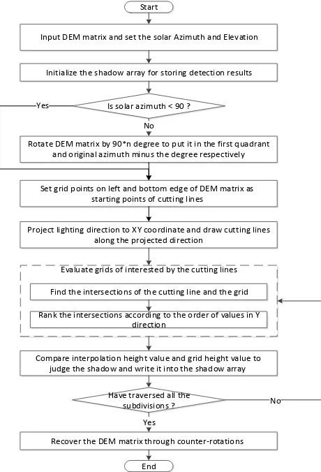
The data we need is DOM (Digital Orthophoto Map) and DEM with geometric registration. Each pixel of DEM is the mean elevation of a unit area. Based on the hypothesis that sun is parallel light source, we can trace the sunlight with the solar elevation and solar azimuth. Take one pixel as example, draw a line from the current pixel to the sun, calculate the interpolation elevation values of the pixels the line passed through and compare the height of real elevation values and interpolation elevation values in the order of the distance from the current pixel, once real elevation is above interpolation elevation, stop the cycle and sign the current pixel as shadow. Calculating one by one, hard shadow binary image is obtained, the processing flow is shown in Figure 1.
Evaluate grids of interested by the cutting lines Start
Input DEM matrix and set the solar Azimuth and Elevation
Is solar azimuth < 90 ?
Set grid points on left and bottom edge of DEM matrix as starting points of cutting lines
Rotate DEM matrix by 90*n degree to put it in the first quadrant and original azimuth minus the degree respectively
Project lighting direction to XY coordinate and draw cutting lines along the projected direction
Have traversed all the subdivisions ?
Find the intersections of the cutting line and the grid Rank the intersections according to the order of values in Y
direction
Yes
No Compare interpolation height value and grid height value to
judge the shadow and write it into the shadow array
Recover the DEM matrix through counter-rotations No
Yes
Initialize the shadow array for storing detection results
End
Figure 1. Flow chart of geometric shadow detection method
3. ANISTROPIC SCATTERING SHADOW surrounding terrain. Traditional shadow compensation method usually adopts isotropic scattering assumption and use terrain information to calculate SVF of shadow pixels. Isotropic model is simple, but it has a certain gap with the actual situation. Skylight scattering means atmospheric particles scattering the sun's rays. The sun apparent position obviously has an
important influence, which cannot be isotropic (Gueymard, 2001). Considering the quantitative compensation of shadow needs the radiation ratio to be as accurate as possible, our method bases on the anisotropic scattering hypothesis.
Isotropic scattering light
Figure 2.Classification of diffuse solar radiation (Qi, 2007)
As shown in Figure 2, the radiation sources that affects the soft shadow can be divided into three; circumsolar radiation, isotropic scattering and horizontal brightening (Ur Rehman, 2015). Because the aerosols have a strong forward scattering component, a substantial portion of the aerosol-scattered diffuse radiation appears to come from a small annular area around the solar disk; this radiation is called circumsolar radiation, which has the maximum radiation. The assumed isotropically distributed component due to Rayleigh scattered radiation and the remaining aerosol scatter not attributed to circumsolar radiation. Horizontal brightening is due to multiple ground reflected radiation, which increase the radiation close to the ground.
Our shadow compensation scheme is to build ground radiative transfer model based on SVF of each pixel, and to calculate the direct radiation, scattering radiation and ground multiple reflectance constant. Then take advantage of anisotropic scattering empirical function with SVF, we can obtain the lost radiation of each shadow pixel. Compensate it into the shadow areas detected before can we get the final shadow free image. The first step is to calculate SVF. Every pixel has its own SVF due to different adjacent terrain obstruction. According to the precision requirement, we can set certain search radius and directions, and calculate SVF of each pixel. On flat terrain, target pixel can receive the scattering radiation from the entire hemisphere sky (Figure 3a) and SVF is 1. When one side is obscured, target pixel can only receive sky scattering radiation from - hemisphere (Figure 3b).
α π-α
(a) (b)
Figure 3 (a) SVF=1, (b) SVF<1.(Li, 1986)
For example, we take east, west, south and north as our search direction (n=2) to calculate SVF of pixel O. Centred on O, take south as the initial orientation, and divide the horizontal plane into 2nsector counter clockwise. Take the 2nlines as intersecting lines, make 2n1 vertical plane, which divide the visible sky hemisphere into 2nportion, similar to the meridian of the earth. Search each direction along the intersecting line; keep the largest elevation angle asi, note that the angle is non-negative. Then we have the SVF as follows.
2
Pokrowski proposed the anisotropic scattering empirical formula as follows (Steven, 1977).
2
For solar zenith angle is 35 degree, relative radiance values are shown in Figure 4. The maximum of the scattering light is around the sun, called circumsolar radiation and the sky where the angle with the sun is 90° has a minimum value. Cross-section through the solar meridian showing measured value and
a fitted analytic approximation based on Pokrowski’s formula.
Figure 4. Relative radiance values for solar zenith angle = 35
(Steven, 1977)
Multiply SVF with anisotropic scattering factor got from the empirical formula, we have an anisotropic sky view factor (ASVF) that considering the anisotropic scattering. After normalization, we can use the ASVF instead of the isotropic one to compensate the shadow.
Set brightness value in non-shadow asEnon, Ediras the direct solar radiation constant andEdif is the diffuse radiation constant of the entire hemisphere. SetVnas ASVF of each non-shadow pixel and
C
is the horizontal brightening constant. Therefore, here is the radiation transmission formula of non-shadow area.non dir dif n
E E E V C (3) Shadow area lacks direct radiation. All the radiation comes from the diffuse radiation and horizontal brightening from the visible sky hemisphere. Set the radiation in shadow asEs, the ASVF of the shadow pixel asVs. Then we have the radiation transmission formula of shadow area.
s dif s
E E V C (4) From above we can conclude that to compensate shadow is to add the scattering radiation and the direct solar radiation from the sky hemisphere that is invisible for shadow area.
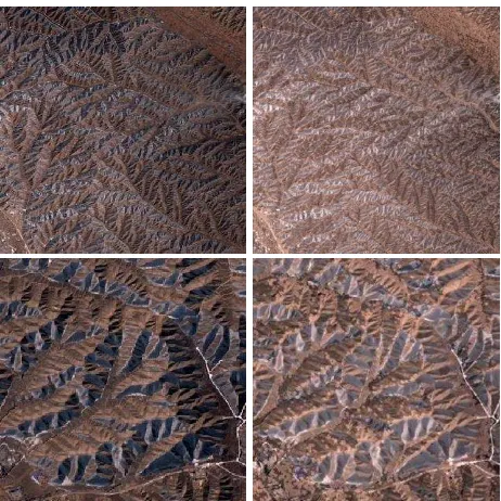
dir n dif satellite image in Lanzhou, China (Figure 6). Solar elevation is 56.253° and solar azimuth is 159.236°.
4.2 Shadow Detection
As shown in Figure 5 and Figure 6, origin image has uneven distribution of the radiation intensity, and covers by little thin cloud at left middle position.
Artificial interpretation picks seed points of shadow manually, chooses appropriate fault tolerant rate to generate planar shadow region. Artificial interpretation is the most reliable one as well as the most time consuming one. Results are largely influenced by the experience of the sampling members, which leads to poor objectivity between different individuals. The finely shadow region exists the possibility of detection error.
(a) (b) (c)
Figure 5. Shadow detection results
(a: original image, b: our result, c: manual interpretation)
(a) (b) (c)
Figure 6. Shadow detection results detail view
(a: original image, b: our result, c: manual interpretation)
From shutter analysis, we can found that the geographical features of our result are in good agreement with the real terrain shadow. Moreover, the result has less problem of loss or fault detection, and not affected by the cloud, which can be overlaid on the orthogonal projection for the subsequent interpretation. Compared with the manual interpretation, our method has no human intervention in the whole process, which largely avoids the time and labour waste.
As we cannot get the real shadow area on the ground, we assume that the artificial interpretation results are the real shadow value, as the quantitative judgment reference. Despite the artificial interpretation results has little missing, it has accurate shadow location and little fault detection. We adopt the
producer’s accuracy as a standard of quantitative assessment of
shadow detection.
From the visual interpretation, the results of geometric method and the manual method have very similar distribution of shadow. However, due to scattering, soft shadow around the boundary has higher intensity and may be omit by the manual interpretation that judges the shadow by its intensity only. Our compensation method needs the lost shadow pixels to be as less as possible. That is also the reason why geometric detection result has a little larger area than the manual one. Divide the total by the correct shadow pixels we get the shadow detection accuracy is 86.9%. The conclusion is that 86.9% of human The International Archives of the Photogrammetry, Remote Sensing and Spatial Information Sciences, Volume XLI-B1, 2016
interpretation shadow points are detected by geometric method, and the lost soft shadow areas of manual interpretation are also included in the hard shadow area of the geometric method and will be compensate later.
Table 1. Comparison of human interpretation and geometric detection method
Shadow 504555 512548 1017103 NonSha 76206 599292 675498
Sum 580761 1111840 1692601
4.3 Shadow Compensation
To verify the accuracy of the shadow compensation method, we set the influence radius of the surrounding terrain is 5 pixels (25 meters), and the detect directions are east, west, south, north, southeast, southwest, northeast, northwest respectively. In each direction, we compare the height of pixels along the direction and within the radius of the current pixel, once the detected pixel is higher than the current one we stop and record the angle between the two connect with plumb line as the SVF of the current direction. Normalize the mean of SVF of all the directions, we have the isotropic SVF.
100% every 30 degrees. In this way, we get 24 partitions. Take the sun azimuth into the anisotropic scattering formula, we have anisotropic scattering factor e of each partitions. As the deviation of the anisotropic scattering factors e is up to an order of magnitude, we did a fourth power to narrow the differences
In our experiment, SVF is within (0.3037, 1). Read the shadow binary imageS, in which shadow areaS 1and non-shadow area S0. Radiation transmission model is shown in (5), given Sand SVF, we can calculate the three constant with indirect adjustment.
Our CPU is Intel Core i5-2500 k, 3.3 GHz, the memory of 8G, ordinary PC, and operating system Windows 7. For DOM and DEM of 1301×1301 pixels, shadow detection takes 11 seconds and shadow compensation takes 0.3 second. From Figure 7, it shows that the compensated shadow areas have obvious improvement in brightness, and the stereo feeling is largely disappeared.
Overall brightness is increased significantly (higher average in shadow area), and the brightness values of the whole image become closer (a significant reduction in overall variance). As we use the average of ASVF to correct the shadow area, there still exists some uneven brightness in the image, remains to be refined in the next research.
Figure 7. Shadow detection results detail view
5. CONCLUSION
High resolution DEM of the world are produced and applied more and more rapidly, which gives us a faster and more accurate way to obtain the shadow’s boundary in the VHR (Very High Resolution) remote sensing images. This paper proposes a shadow detection method by building the geometric model of the sun and the terrain, which is less affected by the image quality, with less broken details, and can be used in the
substantial interpretation directly. What’s more, we innovatively
adopt the anisotropic scattering assumption in shadow compensation. Considering the difference of shadow and non-shadow in the radiation transmission way. It could recover the spectral information of shadow area and produce high-quality shadow free images rapidly. However, we did the experiment without the consideration about the cloud situation. The further research may be focus on refining impact factors including multiple terrain reflectance and the cloud influence.
REFERENCES
Dare, P.M., 2005. Shadow analysis in high-resolution satellite imagery of urban areas. Photogramm Eng Rem S, 71(2): 169-177.
Elbakary, M.I., 2014. Shadow Detection of Man-Made Buildings in High-Resolution Panchromatic Satellite Images. Geoscience and Remote Sensing, IEEE Transactions on, 52(9): 5374-5386.
Finlayson, G.D., 2006. On the removal of shadows from images. Pattern Analysis and Machine Intelligence, IEEE Transactions on, 28(1): 59-68.
Gueymard, C.A., 2001. Parameterized transmittance model for direct beam and circumsolar spectral irradiance. Sol Energy, 71(5): 325-346.
Li, H., 2014. An Adaptive Nonlocal Regularized Shadow Removal Method for Aerial Remote Sensing Images. The International Archives of the Photogrammetry, Remote Sensing and Spatial Information Sciences, Volume XLI-B1, 2016
Geoscience and Remote Sensing, IEEE Transactions on, 52(1): 106-120.
Li, Y., 2005. Integrated shadow removal based on photogrammetry and image analysis. Int J Remote Sens, 26(18): 3911-3929.
Steven, M.D., 1977. Standard distributions of clear sky radiance. Q J Roy Meteor Soc, 103(437): 457-465.
Stevens, M.R., 1995. Locating shadows in aerial photographs using imprecise elevation data. Computer Science Technical Report CS-95-105, Colorado State University, USA.
Tsai, V.J.D., 2006. A comparative study on shadow compensation of color aerial images in invariant color models. Geoscience and Remote Sensing, IEEE Transactions on, 44(6): 1661-1671.
Ur Rehman, N., 2015. A novel method for determining sky view factor for isotropic diffuse radiations for a collector in obstacles-free or urban sites. J Renew Sustain Ener, 7(3): 033110.
Yang, Q., 2012. Shadow Removal Using Bilateral Filtering. Image Processing, IEEE Transactions on, 21(10): 4361-4368.
Li, Xianhua, 1986. A Radiometric Correction of Relief Disturbances in the Remote Sensed Data. Acta Geodaetica et Cartographica Sinica, 15(2): 102-109. (In Chinese)
Qi, Xueyong, 2007. Modification of Atmospheric Correction Model and Surface Reflectance Retrieval from TM Imagery in Rugged Terrain. Remote Sensing Information(04): 3-8+101. (In Chinese)