INTEROPERABILITY MATTER: LEVELS OF DATA SHARING, STARTING FROM A
3D INFORMATION MODELLING
C. Tommasi a, *, C. Achille a
a 3D Survey Group, A.B.C. Department, Politecnico di Milano, Italy - (cinzia.tommasi, cristiana.achille)@polimi.it
Commission II
KEY WORDS: BIM, Interoperability, Cultural Heritage, Accuracy, Standardization, reality-based modelling, data sharing
ABSTRACT:
Nowadays, the adoption of BIM processes in the AEC (Architecture, Engineering and Construction) industry means to be oriented towards synergistic workflows, based on informative instruments capable of realizing the virtual model of the building. The target of this article is to speak about the interoperability matter, approaching the subject through a theoretical part and also a practice example, in order to show how these notions are applicable in real situations. In particular, the case study analysed belongs to the Cultural Heritage field, where it is possible to find some difficulties – both in the modelling and sharing phases – due to the complexity of shapes and elements. Focusing on the interoperability between different software, the questions are: What and how many kind of information can I share? Given that this process leads also to a standardization of the modelled parts, is there the possibility of an accuracy loss?
1. INTRODUCTION
1.1 Building Information Modelling: origins and application
The BIM processes is born by a series of criticalities that come into the light in the AEC industry following the traditional pipeline of work: that approach goes from a bi-dimensional design to a three-dimensional model, mainly using the CAD tools. Unfortunately, this methodology often leads to some problems like:
Lack of planning in the project
Lack of coordination between professional figures belonging both to the same field or to different ones
Lack of a constant project’s monitoring
Reluctance to learn and use new technologies
Inefficient costs management and estimation
Inefficient materials estimation
Inefficient energy waste estimation
In order to understand the consequences of these criticalities, it is useful to know that the 38% of carbon emission in the Us are from buildings (USGBC, 2007), the 30% of the projects do not respect the initial schedule or budget (CMAA Industry Report, 2007), the 92% of project owners said that architects’ drawings are not sufficient for construction (CMAA Owners Survey, 2005), the 5.3% of the costs of a project are due to a change orders (AACE, 2004) and that the 37% of materials used in the construction industry become waste (Economist Magazine, 2002).
The answer to these issues is represented by the Building Information Modelling (BIM) technology, which brought a significantly change of way to work in new construction. It is important to underline that it is not a single software in a single area of interest, but it is a process that involves a multiplicity of
* Corresponding author
software and operators, thanks also to the strong level of interoperability, which permits the information sharing without losing data, monitoring the building through all its life cycle. The result of this technology is a virtual model, which is no more only three-dimensional, but becomes an “n” dimensional one, as there are introduced multiple dimensions: 3D is a visualization model, 4D is the time monitoring model, 5D is the costs estimation, 6D is the energetic analyses and the 7D correspond to the facility management of a building.
Summarizing, the main three features of BIM are:
Multi-dimension and multi-discipline, as it touches all the fields linked to the construction industry, and more: architectural, structural and plumbing design, facility management, serious gaming, simulations, etc…
Information: the model does not end in itself, but it is a container full of different data, from the geometrical, to the estimative, material, physical, energetic, etc… ones.
Interoperability, which lets to share the model and the linked data between different operators and software, without any loss of information
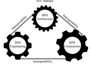
This article is focused on the interoperability aspect because it is the bond that pulls together all the different areas: it makes the gears of BIM Architecture, Engineering and Construction turn as they were in a well-oiled machine. The coordination inside an only one model is better than the one that is possible to obtain in several 2D representations, decreasing the human error and consequently the design and production costs: the information are shared better and faster.
This concept is not new: since always there is the need of dialoguing between applications belonging to the same field– e.g. the case of DXF format for the sharing of vectorial data between products of different software houses-. In the BIM cases this The International Archives of the Photogrammetry, Remote Sensing and Spatial Information Sciences, Volume XLII-2/W3, 2017
necessity became primary, as the integration of different knowledge is the innovation’s essence.
Figure 1. The interoperability bonds together the AEC industry’s gears.
2. STATE OF ART 2.1 Interoperability concept: definition
The widespread of Building Information Modelling processes increases the need to have a complete merging between the application fields. As they are plenty, it is impossible to find a unique software that can handle all the information assigned to each branch, or a single operator that can manage all the aspects regarding a building; for this reason, it is necessary to have some instruments that allow the data sharing among operators and software.
“Software interoperability is seamless data exchange at the software level among diverse applications, each of which may have its own internal data structure. Interoperability is achieved by mapping parts of each participating application’s internal data structure to a universal model and vice versa.” (NIBS, 2008) Analysing the most famous definition of the terms it is possible to introduce two important aspects inner to this concept: i) the fact that somehow many software that works in different ways have to communicate between each other, and consequently ii) that the process of interoperability can lead to a standardization due to the transformation from a model with an internal data structure to a universal one that has to be adapted in another environment.
Therefore, the information’s quality to be shared is beyond the simple graphic data, as the BIM’s elements are real objects made not only of geometrical features, but also materials, quantities, costs, temporal, energetic and structural ones. For this reason, the theme of data exchange was largely investigated by researchers, associations, software houses, industries, etc., building a proper ad-hoc technology, which evolves with the BIM applications and their needs.
2.1.1 BuildingSMART and exchange formats
Today, the exchange data format technology is carried on and developed by an international association, called BuildingSMART. Its activities comprehend the standardization of the processes, workflows and procedures for BIM, supporting the use, the publication and the promotion of open standards. In particular, it is focalized on three standards that represent the levels of interoperability in the BIM environment: IFC (Industry Foundation Classes), IFD (International Framework for Dictionaries or Data Dictionaries) and IDM (Information Delivery Manual). All this three formats are receipted by ISO
(International Organization for Standardization), a regulatory corporation.
The first one, IFC data model, is the format for the information exchange, and also the one more linked to the users. It defines a structured model of data, object-oriented, which contains a system for classifying and describing not only the geometrical or physical attributes of the objects like walls, slabs, etc., but also the quantities, costs and the temporal sequences of elaborations. The current version is IFC 4, accepted also as ISO 16739 standard. The specification related to the data model are defined by MVD (Model View Definition): given that IFC is built to satisfy many different configurations, level of details and users, a MVD provides a way to indicate what information are specifically needed for a particular use. It can be useful in a contract, defining what data has to be provided according to a specific validation model.
The IFD data dictionary, on other hand, is an international dictionary that defines the terms and meaning of entities, products and processes in the AEC industry. While the IFC describes the objects (entities and processes) and their relationships, IFD is a dictionary that gives the definition of these elements and their parameters, making possible a common understanding. To give an example, if I have a generic brick wall 30 cm thick, 3 m tall and 10 m long (and also with all the other properties related), IFC determinates the object itself with these specifications, while the IFD tells that this is a defined wall, that the 30 cm is its thickness, 3 m is the height, 10 m is the length, brick is the material and so on.
Finally, IDM is the standard related to the methodology to capture processes and information during a lifecycle of a building. It satisfies the need to optimize the communication’s quality between different actors of the construction flow: knowing that all the design and management phases bring a lot of data that are not requested all in the same time, in this way the efficiency of the entire cycle is improved as all the participants know when and which kind of information has to be communicate.
The great interest in the theme of exchange format is also testified by the promotion of a survey in January 2017 from BuildingSMART International (BSI) to the users of openBIM and IFC standards, asking what are its main obstacles, potentialities and expectations (BuildingSMART International, 2017).
In conclusion, the IFC format defines how to share data, the IFD describes what is sharing and the IDM permits to know which data has to be shared and when. These three standards give a complete idea of the different levels of interoperability and their specifications, but once defined the formats for the data exchange, it is important to understand where they can be applicable, identifying the relationships that can be established in the interoperability environment.
2.1.2 Bonds in the interoperability environment
The relationships bound by interoperability can be inside or outside the BIM environment, and they are important to understand how is it possible to communicate between different parts and how far the exchange formats can go. In particular, the more reasonable bonds are:
in the same workspace, when different operators are building the same models, e.g. “A” is creating the The International Archives of the Photogrammetry, Remote Sensing and Spatial Information Sciences, Volume XLII-2/W3, 2017
windows and “B” is modelling the curtain walls of the same building
in the same professional field but working with different software belonging to the BIM classification, e.g. “A” is using Autodesk Revit and “B” is using Graphisoft Archicad and they want to share the same architectural model
in the same workspace, working in BIM environment but in different professional fields, e.g. “A” has modelled in Autodesk Revit Architecture, and “B” has to do the MEP (Mechanical, Electrical, Plumbing) model with another BIM software, DDS – CAD (Data Design System) and finally “C” has to run the clash detection – checking if there are some interferences and validating the two models together - with Solibri Model Checker
in the same professional field but working also with software external to BIM environment, e.g. “A” is using Revit but he has to insert some elements from Rhinoceros, a traditional modeller
In different professional fields, sharing data with someone who is not capable of using a BIM software, e.g. “A” is using Revit and has to send the materials computing table to “B” which does not use Revit but he can open it in Microsoft Excel, maybe modify and send it back to “A”, who can update the BIM modelling software.
Some of the relation summarized here are more complex than others, as they consider to create a communication between software that works in a completely different way: this is the case of the interoperability between different application, where for example, one is a BIM program and the other is not. In these conditions, it is not always possible to apply the international standards, and it is necessary to find other ways, especially talking about very complex buildings and shapes, as the ones, for example, belonging to the Cultural Heritage field.
Figure 2. The relationship’s structure of the interoperability’s bonds.
2.1.3 Plug-ins
Sometimes, the answer to the need to exchange between programs that normally can’t communicate can be the use of plug-ins. The need of these connections is testified by the fact that in the last period, the software house developed and multiplied more and more the output and the input in their application: for example, this is the case of Graphisoft.
The former version of Archicad 18 comes with a plug-in called “Rhino - Archicad 18 Connection”, which was able to export from Rhino into Archicad as object format (*.gsm) or a Library Container File (*.lcf), which is a file more complex, made with several gsm together. This process was one-directional.
At the same time, they started also to develop a connection with Grasshopper, a parametric – generative software. With the last release of these plug-ins, divided in three different solutions, now it is possible to have a bi-directional exchange with Rhino in its format *.3dm (Add-on Import/Export Rhinoceros), to create a BIM model through the scripting interface of Grasshopper (Grasshopper - Archicad Live Connection), and finally to convert objects in Rhino in Archicad formats (GSM or LCF).
It is clear that, also the BIM software, even if they belong to the same modelling categories, have all individual inner principles, considering that they are developed by different software houses. For example, in Revit there is a strong families’ hierarchy, while in Archicad, the organization of the objects is different. For this reason, plug-ins can be also applied inside the BIM environment, improving the IFC exchange between software. One example of this case is “Archicad Connection for Revit”, who enhances the interpretation of architectural models in the import/export between Archicad and Revit.
In order to understand what are the communication problems of the software, it is important to define the categorization of the modelling techniques, and what are the differences between them.
2.2 Modelling techniques
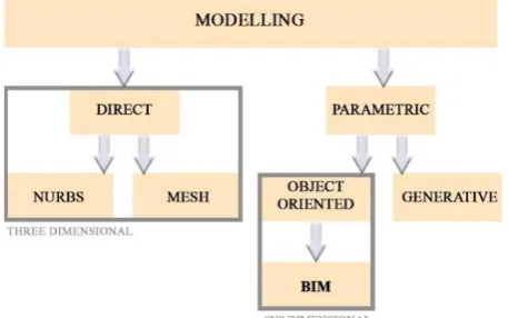
Nowadays, the biggest problem in the interoperability process is to integrate the different workflows coming from the several modelling techniques: it is possible to distinguish two main branches, the direct and the parametric ones (Tommasi, 2016).
Figure 3. The modelling’s categories
The direct modelling is considered the “traditional” way to work: in this environment, the objects have only geometrical or material attributes, and they are defined by mesh or NURBS (Non Uniform Rational Basis - Splines). The final product is a three - dimensional model, which can be reality-based, reaching high levels of detail and accuracy, mostly used for documenting, and/or rendering and visualization purposes. The main limits of this method are i) the impossibility to repeat that elements that have similar shapes but different dimension or orientation and ii) the impossibility to insert information and other data inside the model. For these reasons, the parametric approach is more and more spreading, answering to the need of a parametric and informative model.
The parametric models can be generative or object oriented. In the first case, the objects are represented through an algorithmic process: they only own geometrical or material features but they are de-composed in every single component making them adjustable without categorizations and shape bonds. The final result is not only a model, but also a procedure for the resolution of analogous problems, using that methods when it is necessary to model objects with similar shapes but different measures or orientation.
On the other hand, the object-oriented modelling is a different type of parametrization: it is based on libraries of pre-built elements, belonging to a specific category of real elements – walls, doors, windows, etc. – with not only dimensional attributes but also physical, mechanical, energetic, etc…. The final product is a BIM model, connected to an information database, suitable for a plenty of uses in several construction fields.
DIRECT
PARAMETRIC
GENERATIVE OBJECT -ORIENTED
Kind of objects Mesh and
NURBS algorithms
Prebuilt elements
Information adding
Geometrical parametrization
Life Cycle Management Reality-based (great
accuracy and high definition
Table 1. Confronting the features of the modelling techniques
3. CASE STUDY 3.1 Preface
In the last years, researchers and professionals tried to employ the BIM processes to this particular sector, where there are no regular or standardized elements and the modelling is more complex than in a new building situation. For this reason, the BIM software implement more and more the tools at disposal to the operators who want to obtain a model with a sufficient level of detail for the representation scale selected, becoming more and more accurate: the simplification required to represent an ancient building in a BIM software is increasingly reduced in the last period. Despite of this strong development, there are still cases where the users need to use external software to model the shapes that are too complex to be handled with the BIM process.
In this context born the question of interoperability, is it possible to have it also with models belonging to the Cultural Heritage field? Do the international standards work or are there other way to exchange a complete model with information? And finally, if the interoperability normally leads to a standardization of the model’s parts – fact that in new buildings does not represent a difficulty -, how much accuracy the model loses?
In order to respond to these questions understanding how, what, when and which information can be shared, it was selected a case study, represented by a part of Milan’s Cathedral, (Achille, 2012; Achille, 2014) called “Falconatura” and modelled starting from survey data. In particular, the object was chosen considering some requirements:
It has to be composed by regular and complex parts
It has to be repeated inside the same building with similar shapes but different dimensions
It has to be composed by blocks to be represented in the model
The starting point of the modelling has to be a point cloud
The model has to own a representation scale suitable for the georeferencing of information needed for maintenance activities
To highlight the possibilities and the limits of openBIM technology for the Cultural heritage field, the test phase is focalized on the interoperability between software, in particular among BIM and BIM software, and BIM and external software. The applications chosen were Revit and Archicad as BIM certified software, and Rhinoceros, as it is one of the most common program for the direct and generative modelling of complex shapes belonging to the CH branch.
In this way it is possible to see how many and what information are maintained or lose in the exportation and importation pipeline, whether using a parametric object oriented software that should have a working method very similar to the one used to model the case study, or using a traditional modelling software based on mesh and NURBS, and it is useful for the free-form modelling.
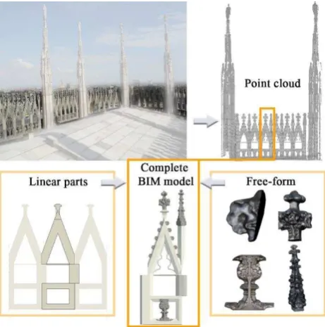
Figure 4. Top line: on the left, the repetition of the “Falconatura” all around the roofs of Milan’s Cathedral; on the
right, the cleaned point cloud of a “falconatura” serie. Bottom line: the complete BIM model of one falconatura, which is composed by regular elements (linear) and free-form (complex
decorations).
3.2 Modelling phase
The data at disposal for the modelling phase came from the integration of photogrammetric and laser scanner survey, acquired for a 1:50 representation scale. After that, the portion was modelled in Revit 2015 to see how the BIM software can handle the entire process of restitution of an ancient building (or part of it), from the point cloud to the final information model. Simultaneously, the same element was also modelled in The International Archives of the Photogrammetry, Remote Sensing and Spatial Information Sciences, Volume XLII-2/W3, 2017
Rhinoceros, a traditional modelling software, in order to compare the achievable result of both methodologies.
It is important to underline that the modelling phase was very time consuming, due to the complexity of the objects to model and to the parametrization process, which needed a detailed planning.
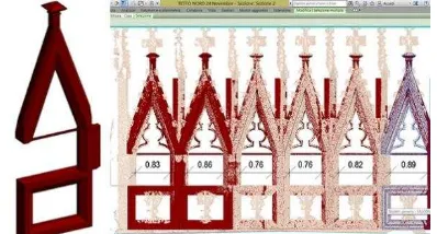
Figure 5. The two models in Rhinoceros (on the left) and in Revit (on the right).
In the Rhinoceros model, it was possible to elaborate the survey data obtaining a model divided in blocks and inserting external meshes for the decoration parts. That elements, came from the photogrammetry survey and they were elaborated with specific software, realizing a very high detailed meshes to be inserted in both Rhino and Revit models.
Also the Revit model was divided in parts respecting the real division of the marble blocks, while the free-form elements were imported after a mesh’s decimation. At the end, there were also linked some information like images, material attributes, comments about the restoring interventions and their time phases.
The last step of the modelling phase was the accuracy test of the two models with the original point cloud, in order to be sure that the 1:50 restitution scale was respected.
Once the final models were finished, it was possible to test the software interoperability, considering the exchanges between another BIM software (Graphisoft Archicad) and also between Revit and Rhinoceros, as it is one of the most diffuse program for the complex shape modelling in the Cultural Heritage field.
EXCHANGES
Revit Rhinoceros SAT format
VisualARQ Rhinoceros Revit
Rhinoceros Archicad Add-on Import/Export Rhinoceros Archicad Rhinoceros
Archicad Revit Archicad Connection for Revit Revit Archicad
Table 2. The tested exchanges (on the left) and the equivalent means to run those exchanges (on the right).
3.3 Exchange phase
From the modelling phase, it is clear that often, in the Cultural Heritage field, it is necessary to integrate different modelling techniques in order to reach a level of detail suitable for the restitution scale chosen.
For this reason, it is important to see what and how many information are maintained during the software’s transfer and also if the level of detail is kept; it is also obvious that if the model sharing happens between a BIM software and a traditional modeller, the importation has to be evaluated only in a geometrical view, because the direct modelling does not support the information adding.
3.3.1 Revit – Rhinoceros
The relationship between Revit and Rhinoceros can be useful when it is necessary to parametrize some elements (e.g. “falconatura”) to speed up the modelling process and insert them in a general model in Rhino.
Figure 6. The Falconatura as it appears in the family editor, with some bonds that make it parametric and adjustable on the point
cloud.
Given that the model in Revit is made by the linear elements and the decimated meshes, it would be useless to try to import in Rhino the free-form elements, which are better handled by the direct modelling software. For this reason, the file imported in Revit will be the falconatura family, which owns some variable bonds that make it parametric.
Before starting, it is also essential to define the parameters that evaluate the quality of the exchange. In this case, they can be only referred to geometrical features, in particular:
Geometry maintenance (accuracy)
Blocks’ division maintenance
Possibility of objects’ editing
The exporting possibilities were: CAD files (DXF, DGN, DWG and SAT), FBX (format for the 3D exchange between autodesk products and IFC (with a Plug-in for Rhino, VisualARQ).
CAD files and FBX
The only connection between Revit and Rhino that does not need plug-ins (which are not open source) is the CAD and FBX formats.
In these cases, the model is imported as mesh, maintaining the geometry and also the blocks division. Using the DWG files, the model is decomposed in lots of meshes. To reach the full editing of the shapes, it was necessary to convert the meshes into NURBS.
From Revit to Rhino: CAD and FBX formats Geometry maintenance
Blocks’ division Objects’ editing
Table 3. Summarizing the result of the IFC importation The International Archives of the Photogrammetry, Remote Sensing and Spatial Information Sciences, Volume XLII-2/W3, 2017
IFC
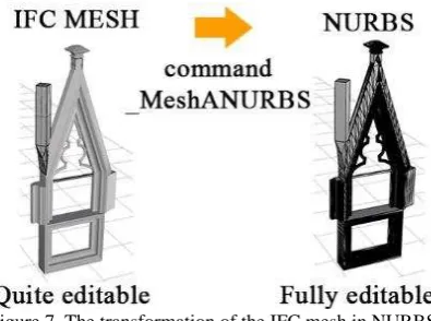
With VisualARQ it is possible to add some features that belong to the parametric modelling. Among these there is also the possibility to import/export in IFC format. This plug-in is not open source and it was used in the 30 days’ trial.
Figure 7. The transformation of the IFC mesh in NURBS.
The IFC file in Rhino maintains the geometry and the blocks’ division, and it is imported as mesh, a category that in Rhino owns limitation regarding the geometrical editing of the shapes. To solve it, it was enough to convert the mesh into NURBS: in this way the model can be completely modified.
From Revit to Rhino: IFC format Geometry maintenance
Blocks’ division Objects’ editing
Table 4. Summarizing the result of the IFC importation
3.3.2 Rhinoceros - Revit
Sometimes, the most complex part of a building (like decorations) can be already modelled in Rhino and has to be transferred in the BIM model Revit. In this case, the parameters to evaluate in the exchange are:
Geometry maintenance (accuracy)
Blocks’ division maintenance
Possibility of objects’ editing
Geometrical parametrization
Information adding
Volume counting
The model was first exported in ACIS SAT format (3D CAD), which contains all the data about the geometry and topology of the elements, and then with VisualARQ it was also tried the IFC path.
ACIS SAT format
The first test was the exporting of the model from Rhino in ACIS and the importing in Revit environment. The file sat excluded the meshes from the exporting, so Rhinoceros conserve only the parts modelled in his workspace (as told before, the free-form were created with a photogrammetry software).
In this condition, the element was imported as one block, without the possibility to modify it and neither to parametrize it in the family editor. The only operation possible to do is the information adding, assigning to the element a family.
It is also achievable the division in blocks of the element, exporting its parts one by one and importing them in Revit: the
parametrization it is still not possible, but at least the falconatura is divided in blocks and the information can be linked specifically.
Figure 8. The model in Revit has no meshes and it is not possible to attribute variable bonds for parametrization, but it is
possible to add information.
From Rhino to Revit: ACIS SAT
Geometry maintenance
No meshes
Blocks’ division only imp/exporting them one by one
Objects’ editing Geometrical parametrization
Information adding
Volume counting only with the attribution of a family
Table 5. Summarizing the result of the SAT test.
IFC Format with VisualARQ
With the VisualARQ plug-in is possible to export from Rhino in IFC 2x3 format (the last release is IFC 4 and the 5 is already in early planning), making possible to communicate with Revit in the BIM common language. Of course, the IFC 2x3 version has some limitations, improved in the new version - where are also enhanced the parametric features of the elements - (Liebich, 2013).
At first, it was created a IFC file with also the meshes included, but it was not possible to open it in Revit (due to the big dimension of the file, < 500 Mb), so it was exported a file without the meshes inside it. This behaviour was expected because, as already told, in the modelling phase of Revit model it was necessary to decimate the meshes before importing them in the workspace and consequently, it was difficult that it can handle the entire Rhino model with the high definition free-form elements.
Before exporting the element, it is important to modify in Rhino its family (in this case, wall), in order to be able to change the material once it will be imported in Revit. Otherwise, the object will be classified as “Generic Models”, a family category that does not allow to add material information.
Once imported in Revit, the falconatura is divided in single blocks and the geometry is kept. Unfortunately, it is possible to modify and counting the volume only the elements made with a linear extrusion in Rhino, while the parametrization is not The International Archives of the Photogrammetry, Remote Sensing and Spatial Information Sciences, Volume XLII-2/W3, 2017
possible as the IFC format can’t be imported in the family editor (only CAD files).
Figure 9. In the Revit workspace, only the blocks modelled with a linear extrusion in Rhino can be edited and counted the
volume.
From Rhino to Revit: IFC
Geometry maintenance
No meshes Blocks’ division
Objects’ editing
only the linear blocks Geometrical parametrization
Information adding Volume counting
only with the attribution of a family in Rhino (material)
only with linear blocks (volume) Table 6. Summarizing the result of the IFC test.
3.3.3 Rhinoceros – Archicad
Open source Plug-ins
It is being years that Graphisoft and McNeel work together to create a bridge between Archicad and Rhinoceros. The result of the collaboration is a series of plug-ins: in particular, working in the Rhino environment, it is useful “Rhinoceros - GDL converter” and “Rhino LCF Observer”. The first one is meant for the exportation of standalone objects (*.gsm format), while the second one is made for more complex structures, using the Archicad’s library containers (*.lcf).
The first test was running exporting the element in a LCF format, and choosing to maintain the meshes at their maximum resolution. In Archicad, it is necessary to link the library file to the project and then place the single objects. The division in blocks is maintained and all the objects (meshes included) are loaded and visualize correctly, and it is also possible to add all the information. Regarding the parametrization and editing part, the geometrical features can’t be selected and modified.
Figure 10. Both the linear and free-form elements are visualized correctly with the possibility of adding information, while the
geometrical parameters are not editable.
From Rhino to Archicad: GSM and LCF Geometry maintenance
Blocks’ division Objects’ editing Geometrical parametrization
Information adding
Table 7. Summarizing the result of the LCF test.
IFC
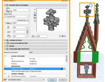
The second test was made by using the IFC file created from Rhino, with all the meshes included and that Revit wasn’t able to open. Archicad opened correctly the file, which was divided in blocks and with the possibility to assign a categorization to each element and consequently, all the information. Regarding the parametrization, the geometrical properties are shown, but the numbers can’t be changed.
Figure 11. The complete IFC model, with the full resolution mesh.
From Rhino to Archicad: IFC Geometry maintenance
Blocks’ division Objects’ editing Geometrical parametrization
Information adding
Table 8. Summarizing the result of the IFC test.
3.3.4 Revit - Archicad
After the trials between BIM software and a “traditional” one, it was also interesting to test the IFC connection between two BIM software. With Revit and Archicad, it is possible to download a The International Archives of the Photogrammetry, Remote Sensing and Spatial Information Sciences, Volume XLII-2/W3, 2017
freeware plug-in which improves the IFC connection between them, “Archicad connection for Revit 2017”.
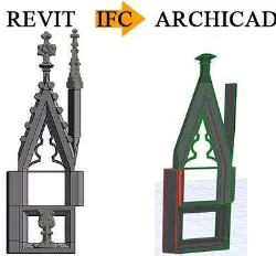
Before importing in Archicad, they were assigned in Revit some properties like images, comments and creation phases, testing also the information and data maintenance.
The final result preserved the geometry (but not the meshes), the block division, and the information but again the elements were not geometrically editable.
Figure 12. The complete IFC model, from Revit to Archicad.
From Revit to Archicad: IFC Geometry maintenance
Blocks’ division Objects’ editing Geometrical parametrization
Information adding Information maintenance
Table 9. Summarizing the result of the IFC test.
4. CONCLUSIONS
Thanks to the test phase it is possible to try to answer to these questions, located in the first part of the article: “Is it possible to have interoperability also with models belonging to the Cultural Heritage field? Do the international standards work or are there other way to exchange a complete model with information? And finally, if the interoperability normally leads to a standardization of the model’s parts – fact that in new buildings does not represent a difficulty -, how much accuracy the model loses?”
The trials conducted shows what aspects work better and what is still to enhance, knowing that, not so ahead in the future, the limits underlined in this article will be more and more reduced.
First, speaking about the interoperability between Rhinoceros and Revit/Archicad, the results are very similar, even if Archicad can handle the heavy meshes more. The aspect to improve in the exchange from an external software to a BIM software is the geometrical editing: it would be very interesting if also the objects modelled with Rhinoceros were parametric, including the more complex ones.
On the other hand, also the IFC exchange between BIM software has to improve the editing aspect: the geometries should be more editable and flexible as they were in their native software. Also the meshes should be counted in order to not lose the accuracy of the model.
In conclusion, the interoperability does not always work completely with the complex elements of Cultural Heritage field: there are some aspects to be improved, especially regarding the parametrization of the geometries and their editing. Some steps are already done: the new release of IFC format, the 4, tries to
overcome some limitations, and the 5 is already in progress; the plug-ins are always renovated with the new versions of the software.
As all the technological processes, the updates will come out more and more often, and the time for developing and problems solving will be reduced, and soon the software, which now have a good level of interoperability, will reach an excellent level.
ACKNOWLEDGEMENTS
Strongly thanks to all colleagues of 3DSurvey Laboratory and students that contribute to this work.
Special thanks to Francesca Lofurno and Federica Pietrucci for their graduation thesis “BIM e Beni Culturali: un modello informativo per il Duomo di Milano”, Politecnico di Milano, 2016.
REFERENCES Understanding IFC, 2017, until 27th January
https://www.surveymonkey.co.uk/r/understandIFC (last access: November 2016)
BuildingSMART International,
https://www.buildingsmart.org (last access: January 2017) https://www.buildingsmart-tech.org (last access: January 2017)
U.S. Green Building Council (USGBC),
https://www.usgbc.com (last access: December 2016)
Club Managers Association of America (CMAA) https://www.cmaa.org (last access: December 2016)
AACE International, AACE International Recommended Practice n° 25R-03, Estimating Lost Labor Productivity in Construction Claims, TCM Framework: 6.4 – Forensic Performance Assessment, 2004
Tommasi, C., Achille, C., Fassi, F., 2016, From point cloud to BIM: a modelling challenge in the cultural heritage field. Int. Arch. Photogramm. Remote Sens. Spatial Inf. Sci., XLI-B5, 429-436, doi:10.5194/isprs-archives-XLI-B5-429-2016, 2016
Achille, C., Fassi, F., Fregonese, F., 2012, 4 Years history: From 2D to BIM for CH: The main spire on Milan Cathedral, in Virtual Systems and Multimedia (VSMM), 18th International Conference on Virtual Systems in the Information Society, pp.377-382, 2-5 Sept. 2012, doi: 10.1109/VSMM.2012.6365948
Achille, C., Fassi, F., Mandelli, A., Moerlin, B., 2014, The yards of the Milan cathedral: tradition and BIM, in Proceedings of the International Conference Preventive and Planned Conservation, ICT per il miglioramento del processo conservativo, Monza, Mantova, 5-9 May 2014, ISBN 978-88-404-0318-2
Economist Magazine,
https://www.economist.com (last access: December 2016)
Dr. Thomas Liebich, IFC4 2013– The new buildingSMART Standard - Official Release Date of buildingSMART’s IFC4 – 12. March 2013 Official Release Date of ISO 16739 – 21. March 2013, oral presentation http://www.buildingsmart-tech.org/about-us/msg (last access: January 2017)