IMPROVED
UAV-BORNE
3D
MAPPING
BY
FUSING
OPTICAL
AND
LASERSCANNER
DATA
B. Jutzi a , M. Weinmann a , J. Meidow b
a
Institute of Photogrammetry and Remote Sensing, Karlsruhe Institute of Technology (KIT), Germany {Boris.Jutzi, Martin.Weinmann}@kit.edu
b
Fraunhofer Institute of Optronics, System Technologies and Image Exploitation (IOSB), Germany [email protected]
Commission I, ICWG I/Vb
KEY WORDS: UAV, multi-pulse laserscanning, sensor calibration, self-localization, data fusion ABSTRACT:
In this paper, a new method for fusing optical and laserscanner data is presented for improved UAV-borne 3D mapping. We propose to equip an unmanned aerial vehicle (UAV) with a small platform which includes two sensors: a standard low-cost digital camera and a lightweight Hokuyo UTM-30LX-EW laserscanning device (210 g without cable). Initially, a calibration is carried out for the utilized devices. This involves a geometric camera calibration and the estimation of the position and orientation offset between the two sensors by lever-arm and bore-sight calibration. Subsequently, a feature tracking is performed through the image sequence by considering extracted interest points as well as the projected 3D laser points. These 2D results are fused with the measured laser distances and fed into a bundle adjustment in order to obtain a Simultaneous Localization and Mapping (SLAM). It is demonstrated that an improvement in terms of precision for the pose estimation is derived by fusing optical and laserscanner data.
1. INTRODUCTION
Nowadays unmanned aerial vehicles (UAVs) are promising platforms for capturing spatial information. As automatically operating low-cost solutions they can be brought easily to the surveying field. Typically these devices are equipped with optical sensors to support the navigation of the platform or to transmit observations to the operator. By collecting the data and processing the captured images, even an unknown environment can be explored and reconstructed (Bulatov et al., 2012). To enable this, Simultaneous Localization and Mapping (SLAM) has to be conducted as specified by Durrant-Whyte & Bailey (2006):
‘SLAM is a process by which a mobile robot can build a map of an environment and at the same time use this map to deduce its location. In SLAM both the trajectory of the platform and the location of all landmarks are estimated on-line without the need for any a priori knowledge of location.’
For performing SLAM with optical sensors, a successful and precise localization of the unmanned aircraft system (UAS) and a simultaneous 3D mapping of the environment can be gained by sensing distinctive elements of the environment, referred to as landmarks. Unfortunately, for these 3D landmarks usually no prior knowledge about their location is given and therefore the 3D position of the landmarks has to be estimated by utilizing descriptive 2D image features from various observations as accurate as possible. Instead of estimating the 3D position of the landmarks with passive sensors, an accurate measurement with active sensors could be practicable (Weinmann et al., 2011). Therefore laser range measurements are usually the first choice, but unfortunately laserscanners are typically bulky and heavy.
Due to the rapid and substantial progress in miniaturizing technology, the latest developments allow to mount suitable
laserscanners on UASs. For instance, Nagai et al. (2009) presented a UAV-borne 3D mapping system equipped with IMU, GPS receiver, two digital cameras, two IR cameras and a laserscanner. Together, the components have a weight of more than 7 kg and for this reason a helicopter-like UAS has been constructed. The system is not only able to simultaneously capture geometric 3D information and radiometric information, i.e. textures, but also to derive a vegetation index due to the use of IR cameras as well as to operate for a long time of about 1 h. The total weight of the platform is however 330 kg. Hence, the system is neither low-cost nor easy to bring to the surveying field. A smaller UAS for close-range rapid monitoring has been proposed by Choi & Lee (2011). This system integrates different types of sensors and supporting modules. Among these, there are GPS receiver and IMU as well as two digital cameras and a laserscanner. The whole system for data acquisition has a weight above 10 kg. As a result, a high-quality DEM and orthophotos can be obtained, but the use of a relatively large UAV is required due to the large payload. A further platform equipped with IMU, GPS, camera and laserscanner has recently been presented by Wallace et al. (2012) and specially designed with respect to low costs and maximum flying time. However, the system only allows for short flights of several minutes for a relatively heavy payload of up to 2.8 kg. Hence, the system is only suitable for acquiring point cloud data for a relatively small area.
As a consequence lightweight systems are desirable for capturing larger 3D environments with low costs. Such systems can be established by reducing the number of components and, for being able to use mini UAVs, by selecting lightweight devices for the relevant components. In this context, the applied laserscanner has been a critical component for a long time. Since only a few months, the new lightweight single-line laserscanner Hokuyo UTM-30LX-EW is available (210 g without cable), which allows capturing multiple reflections and their corresponding intensity values for each transmitted laser pulse.
In this paper, a new method for fusing optical and laserscanner data is proposed for improved UAV-borne 3D mapping. The key issue of this method is the precise determination of 3D landmarks. Therefore, optical and laserscanner data are fused by the following processing steps: a) a geometric camera calibration is conducted to determine the linear and nonlinear intrinsic parameters of the camera, b) the alignment between camera and laserscanner is determined by a specific experimental measurement setup to consider the radiometric and geometric properties of the devices, c) by utilizing the lever-arm and the bore-sight between both devices, the optical and laserscanner data are fused by projecting the 3D laserscanning measurements onto the image plane; for each projection with sub-pixel accuracy the image coordinates of these specific interest points are known and the corresponding range values are given by the laserscanner range measurement, d) by applying the Lucas-Kanade tracker, the given interest points of the current image frame n are matched to image areas of the following consecutive image frame (n+1); the known 3D positions of the landmarks observed in image n are now linked to image coordinates of the image frame (n+1) with sub-pixel accuracy; another significant advantage of utilizing the given range measurement of the laserscanner is that the relation between the scaling of the observations is known as well, e) the above mentioned steps are repeated for all image frames, and f) finally the trajectory of the UAS can be estimated and evaluated.
After presenting the methodology for improved UAV-borne 3D mapping in Section 2, the configuration of the sensor platform is described in Section 3. Subsequently, in Section 4, details for the calibration of the used sensors are specified. In Section 5, the experimental setup is described and evaluation results are presented. The derived results are discussed in Section 6. Finally, in Section 7, the content of the entire paper is concluded and suggestions for future work are outlined.
2. METHODOLOGY
The workflow can be separated into two main parts. Firstly in Section 2.1, a system calibration for the utilized digital camera and the laserscanner is carried out by geometric camera calibration and estimation of the position and orientation offset between the two sensors by lever-arm and bore-sight calibration. Secondly in Section 2.2, we perform a feature tracking through the image sequence considering extracted interest points as well as the projected 3D laser points. Results of sufficient precision and the measured laser distances are coordinate frame to allow further online processing.
Geometric camera calibration
To obtain precise results, a geometric camera calibration has to be carried out. We utilized the Camera Calibration Toolbox for Matlab (Bouget, 2010) to determine the principal distance, the coordinates of the principal point, and the scale difference. Furthermore, the lens parameters of Brown’s distortion model (Brown 1966), had been estimated and used for image rectification.
Lever-arm and bore-sight calibration
Furthermore the offset in position and orientation between the camera and the laserscanner has to be estimated, i.e. a 3D motion parameterized by a rotation and translation. For an accurate estimation the captured data itself has to be used, because other measurement principles (e.g. like utilizing a goniometer) are not suitable. For this reason a so-called self-calibration is applied to find correspondences between measurements of different types: an image captured with a camera in the visible domain (2D data) and single range/intensity measurements on a scan line captured with a laserscanner (1D data). Therefore a specific experimental measurement setup was developed to determine for each laserscanner measurement (3D point) the corresponding image coordinate (2D point). More details are presented in Section 4. 2.2 Online processing
With the UAV application in mind, we have to cope with a continuous data stream of images and laser distance measurements. Therefore, we envisage the use of conventional feature extraction and tracking enriched by range observations within the framework of a sliding window adjustment solving the SLAM task.
Feature extraction and matching
Starting point for the image processing is the extraction of salient features in each image of the sequence. We exploit the Förstner operator (Förstner and Gülch, 1987) to accomplish this task; however, derivatives and alternatives – especially scale invariant feature operators – are conceivable, too. Since we are dealing with a video stream, the application of conventional pyramidal Lucas-Kanade tracker (Lucas and Kanade, 1981) appears to be sufficient to track these landmarks through the subsequent images.
The measured 3D laser points can be projected with subpixel precision into each corresponding image, yielding additional sets of image points to be tracked. Since we cannot expect these image features to appear in textured regions, an assessment of the ‘trackability’ of these image points is mandatory. This can be accomplished by considering the precision of the point coordinates. We truncate tracks containing image points with a positional uncertainty above a certain threshold.
Of course, depending on the computational resources at hand, this process can be made more robust and reliable by enforcing the epipolar constraints with a subsequent guided matching. This can be achieved by applying the Random Sample Consensus (RANSAC) to account for outliers (Fischler and Bolles, 1981).
Simultaneous Localization and Mapping
With the assumption of a static scene we are planning to adopt a sliding window bundle adjustment (e.g. Beder and Steffen, 2008) for the solution of the SLAM problem. This offers the possibility of re-linearization within these windows consisting of several consecutive frames with images and laser distance measurements.
The ongoing incorporation of the distance measurements into the adjustment process introduces scale information and prevents a drift in scale. Furthermore, the result is expected to be more accurate due to the improved geometry and determinability of parameters. The measured laser distances are considered simply by additional observational equations.
The ratio of baseline length and depth of scene points is usually critical for UAV scenarios with rather short tracks of image points. Therefore we apply a bundle adjustment which allows for 3D points far away as proposed in (Schneider et al., 2012). Approximate values for the landmark positions can be obtained by spatial forward sectioning and for the 3D laser points by polar point determination. For the calculation of approximate poses a simple motion model and the corresponding extrapolation appears to be sufficient in most cases.
Using image observations only, the obtained photogrammetric model is determined up to a spatial similarity transformation. This gauge freedom can be fixed by applying the usual centroid constraints for the approximate parameters, i.e. scale, position and orientation of the approximate values are preserved (McGlone et al., 2004). The application of a well-defined datum definition is crucial for the fair comparison of results with and without laser measurements in Section 5.2.
3. SENSOR PLATFORM FOR UAV
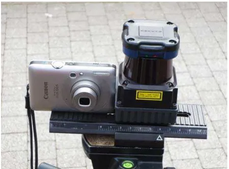
We are planning to equip an UAV with a small platform (Figure 1) which includes two sensors: a digital camera and a laserscanning device. To check the feasibility and the system’s performance, we carried out terrestrial experiments.
3.1 Digital camera - Canon Digital IXUS 100 IS
For digital imaging the standard consumer camera Canon Digital IXUS 100 IS is used. The camera has a 1/2.3-Inch-Type-CCD chip with 4000×3000 pixel and a field-of-view in the range of 66.5° to 24.41°. The total weight including battery and memory card is 133 g.
3.2 Laserscanner device - Hokuyo UTM-30LX-EW For laser scanning the lightweight single-line laserscanner Hokuyo UTM-30LX-EW is utilized. It has a weight of only 210 g without cable. The range measurement resolution is 1 mm and the accuracy is ±50 mm within a 10 to 30 m range (with an accuracy of σ < 30 mm for indoor environments with less than 1000 Lx). The pulse repetition rate is 43 kHz, and the device has multiple reflection capturing capabilities. For each reflected laser pulse the range and the corresponding intensity value are measured. Furthermore, as it is typical for such devices, the laserscanner is operating with regular scan angle steps and the scan is given by a scan line with 1080 sampling points for 270°.
Figure 1. The two sensor devices utilized for the experiments: digital camera and the laserscanner, are mounted on a platform and the alignment in terms of position (lever-arm) offset and the orientation (bore-sight) offset between both sensors is experimentally determined (Section 4.2). For all laserscanning measurements within the field-of-view of the camera of the respective image coordinates and the corresponding 3D points are determined.
4.1 Geometric camera calibration
A standard geometric camera calibration was applied by utilizing the Camera Calibration Toolbox for Matlab (Bouguet, 2010). This toolbox is based on Brown's model which allows correcting radial and tangential lens distortions (Brown, 1966). 4.2 Lever-arm and bore-sight calibration
To estimate the alignment between camera and laserscanner a specific experimental measurement setup was developed. The general goal of this task is to find the corresponding coordinates for each laserscanning measurement within the camera’s field-of-view. Therefore the lever-arm and the bore-sight between the two devices have to be determined.
To gain a short lever-arm, which is essential for obtaining a high overlap between laser projection and image content, the two devices are mounted on a platform with small position offset. After mounting, the manually measured lever-arm of the devices was tLA = [60 mm, 40 mm, 0 mm].
For bore-sight calibration the orientation between camera and laserscanner has to be determined by estimating the coordinates of the laser projections onto the image plane. To determine manually the coordinates of these projections is time-consuming due to the large number of points. In our case 266 coordinates have to be determined for the given maximum field-of-view of 66.5°. Instead of determining all 266 coordinates, it is proposed to use an empirically defined number of supporting points and linearly interpolate the values in between. For this purpose, the coordinates of 5 supporting points selected by steps of 10° (uniformly distributed) have been measured and manually determined (Figure 5). Then the 5 supporting points are fitted to a line. In a next step the intervals between fitted supporting points are regularly subdivided by points with equal spacing, where for each laserscanning measurement the corresponding 1D coordinate raster is calculated with sub-pixel accuracy.
0 500 1000 1500 2000 2500 3000 3500 4000
1545
Figure 2. The estimated results of the image coordinates for the given laserscanning line: 5 measured supporting points (blue stars), 5 fitted supporting points (red circles), and values in between for representing each laserscanning measurement (green dots).
The derived results become visible in Figure 2. For visualization purposes a different scale between abscissa and ordinate coordinates was selected.
Then the 3D object points calculated by the laserscanner range measurement and scan angle can be projected to the image plane. By considering the aforementioned system calibration, for all laserscanning measurements the image coordinates and the corresponding 3D points can be provided to allow the following online processing.
Figure 3 gives an impression of the calibration results for an outdoor scene. In Figure 3a the green line represents the scan line on the image. The respective range values are represented qualitatively by the red dotted vertical lines. Furthermore the corresponding range values are depicted in Figure 3b.
a
0 500 1000 1500 2000 2500 3000 3500 4000 5
10 15 20 25
abscissa coordinate
ra
n
g
e
[
m
]
b
Figure 3. Calibration results: (a) outdoor scene with scan line (green solid line) and qualitative representation of the range values (red dotted vertical lines), (b) corresponding range values.
5. ONLINE PROCESSING
For a proof of the concept and for convenience, we performed terrestrial experiments with the sensor system. For this purpose we initially applied the proposed procedures to obtain the intrinsic sensor parameters and the sensors’ relative orientation. Concerning the pose estimation and scene mapping, we strive for real-time capability. Therefore, we only introduced evaluation strategies enabling online processing later on board. In the following we explicate the experiments and the corresponding results.
5.1 Experimental setup
We used the system described in Section 3 and captured a sequence of four images and corresponding laser scans. After
the first acquisition, the system has been moved 0.25 m up, then 2 m to the right, and 0.25 m down. To account for the low resolution camera envisaged for the flying system, the images have been down sampled by a factor of 4, yielding images of 744×1000 pixel. In the first image salient image points corresponding to landmarks have been extracted by the Förstner operator. These image points and the projected 3D laser points of the first scan have been tracked through the sequence by the Lucas-Kanade tracker. Thereby, a positional precision of σmax = 0.05 pixel has been required for all point positions (extracted and tracked points). Observations of image points with a positional precision above this threshold have been discarded in order to account for outliers, salient image features due to occlusions, non-static scenes, etc. Figure 4 shows the second and the fourth image with tracked landmarks and laser points. The measured distances d to the 3D laser points have been introduced into the adjustment with a standard deviation of σd = 0.05 m.
a
b
Figure 4. The second (a) and the fourth image (b) with marked image features (red crosses), projected laser points (red circles), and their tracks (blue lines).
5.2 Evaluation Results
For an evaluation we performed a comparison of bundle adjustment with and without exploiting the range information given by the laserscanner. For a proper comparison of the
results we enforced identical datum definitions in all experiments, i.e. the gauge freedom has only been fixed with the 3D points referring to landmarks, not laser points.
Our experiences with experiments using image information only revealed that a regularization by the Levenberg-Marquardt approach implying many iterations is often mandatory to cope with a weak geometry and the resulting poor determinability of the parameters. In the experiments presented in this section less iterations are needed when exploiting the information of the laserscanner (cf. Table 1).
Experiment #1 #2 #3
Observations 768
landmarks
1000 landmarks
+ projected laser points
1029 landmarks
+ projected laser points
+ distances
3D points 96 96+29 96+29
σ0 0.76 0.67 0.85
Relative redundancy
0.60 0.61 0.62
Iterations 6 5 4
Precision index
1 7.2 24.1
Table 1: Comparison of the adjustment results for three experiments including relative redundancy, estimated factor σ0, number of required iterations, and precision index indicating the change in precision for the pose parameter w.r.t. the first experiment.
More important, the average precision of the estimated pose parameters increases considerably which reveals the benefit of considering the additional distance observations within the adjustment. To prove this, we specify the improvement in precision for the pose estimates with respect to the results of the first experiment which does not take the laser data into account (Table 1). The introduced precision index expresses the increase (or decrease) in precision by averaging the ratios of estimated standard deviations for the pose parameters. Hence, a factor greater than one expresses the improvement w.r.t. to the first experiment.
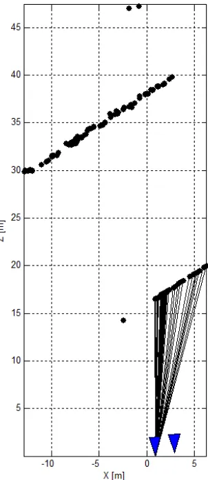
These improvements pave the way for the creation of products such as depth maps with higher precision. Figure 5 shows the results for the bundle adjustment with range measurements.
6. DISCUSSION
The experiments revealed that further aspects should be considered. These also address the selected sensor configuration. The camera has a non-switchable auto-focus function which can still take influence on the results as, depending on the selected test environment, the camera calibration is carried out for a defined range interval. Hence, the estimated values for the camera parameters might be biased for
ranges beyond the interval borders. We would therefore recommend using a prime lens with adjustable focus and lens aperture to adapt the depth of focus. Then the camera calibration parameters should also be valid for different ranges. Furthermore, the manufacturer provides the measurement accuracy of the lightweight laserscanner only with respect to the range measurement, i.e. values for range accuracy, measurement resolution and repeated accuracy, but unfortunately not for the scan angles. Therefore the scan angle properties should be deeper investigated in the future.
Additionally an enhanced measurement principle should be developed to improve the supporting point measurement accuracy. Even better than to measure only 5 supporting points might be a strategy to precisely determine the coordinates of all laser points on the image plane, in our example 266 points.
Figure 5: Results of the bundle adjustment, drawn in nadir view. Two of the four camera poses denoted as triangles (projected blue pyramids) can be seen from this aspect. 3D points are denoted by dots, the straight line segments refer to the laser observations measured at the system’s first pose.
7. CONCLUSIONS AND OUTLOOK
The availability of small and lightweight laserscanners for UAV applications provokes the need for innovative concepts to fuse image and range measurements properly. In this contribution we proposed a stringent approach to integrate range measurements provided by a line scanner and observations of a single camera into a joint sliding window bundle adjustment. Necessary
prerequisites are a precise camera calibration and lever-arm and bore-sight determination respectively for the sensor platform. The conducted terrestrial experiments prove the feasibility and usability of the approach. The additional consideration of range measurements introduces and preserves scale information, eases initialization procedures, and clearly improves the adjustment results. Furthermore, the additional 3D points generated by the laser densify the scene information, i.e. the points’ distribution on the surfaces becomes more uniformly distributed.
For future work a UAV-borne system and longer sequences will be investigated. Derived photogrammetric products such as digital surface models or depth maps can be expected to be more accurate with the increased precision of the intermediate results (sensor trajectory and scene points).
With the proposed method a major contribution for an improved UAV-borne mapping is given. Based on the determined accurate trajectory, this approach can be extended by considering dense matching techniques, e.g. given by the semi-global matching approach (Hirschmüller, 2008) to gain a precise 3D model of the environment or by the use of different types of cameras such as the combination of RGB, multispectral and thermal infrared cameras (Lucieer et al., 2012; Weinmann et al., 2012) for mapping different environmental characteristics.
ACKNOWLEDGEMENT
The authors would like to thank Matthias Kapica for assistance during the measurement campaign.
REFERENCES
Beder, C., Steffen, R., 2008. Incremental estimation without specifying a-priori covariance matrices for the novel parameters. IEEE Computer Society Conference on Computer Vision and Pattern Recognition Workshops (CVPRW), pp. 1-6.
Bouguet, J. B., 2010. Camera Calibration Toolbox: http://www vision.caltech.edu/bouguetj/calib_doc/ (last access on 30 April 2013).
Brown, D. C., 1966. Decentering distortion of lenses. Photo-grammetric Engineering, Vol. 32 (3), pp. 444-462.
Bulatov, D., Rottensteiner, F., Schulz, K., 2012. Context-based urban terrain reconstruction from images and videos. ISPRS Annals of the Photogrammetry, Remote Sensing and Spatial Information Sciences, Vol. I-3, pp. 185-190.
Choi, K., Lee, I., 2011. A UAV-based close-range rapid aerial monitoring system for emergency responses. International Archives of the Photogrammetry, Remote Sensing and Spatial Information Sciences, Vol. 38-1/C22, pp. 247-252.
Durrant-Whyte, H., Bailey, T., 2006. Simultaneous Localization and Mapping (SLAM): Part I The Essential Algorithms. Robotics and Automation Magazine, Vol. 13 (2), pp. 99-110. doi:10.1109/MRA.2006.1638022
Fischler, M. A., Bolles, R. C., 1981. Random Sample Consensus: A Paradigm for Model Fitting with Applications to Image Analysis and Automated Cartography. Communications of the ACM, Vol. 24 (6), pp. 381–395.
Förstner, W., Gülch, E., 1987. A fast operator for detection and precise location of distinct points, corners and centres of circular features. ISPRS Intercommission Workshop, pp. 281-305.
Hirschmüller, H., 2008. Stereo processing by semi-global matching and mutual information. IEEE Transactions on Pattern Analysis and Machine Intelligence 30 (2), pp. 328-341. Lucas, B. T., Kanade, T., 1981. An iterative image registration technique with an application to stereo vision. Proceedings of the 7th International Joint Conference on Artificial Intelligence (IJCAI), Vol. 2, pp. 674-679.
Lucieer, A., Robinson, S., Turner, D., Harwin, S., Kelcey, J., 2012. Using a micro-UAV for ultra-high resolution multi-sensor observations of antarctic moss beds. International Archives of the Photogrammetry, Remote Sensing and Spatial Information Sciences, Vol. 39, Part B1, pp. 429-433.
McGlone, J. C., Mikhail, E. M., Bethel, J., 2004. Manual of Photogrammetry. 5th Edition. American Society for Photogrammetry and Remote Sensing, Bethesda MD, United States.
Nagai, M., Chen, T., Shibasaki, R., Kumagai, H., Ahmed, A., 2011. UAV-borne 3-D mapping system by multisensor integration. IEEE Transactions on Geoscience and Remote Sensing 47 (3), pp. 701-708.
Schneider, J., Schindler, F., Läbe, T., Förstner, W., 2012. Bundle adjustment for multi-camera systems with points at infinity. ISPRS Annals of Photogrammetry, Remote Sensing and Spatial Information Sciences, Vol. I-3, pp. 75-80.
Wallace, L. O., Lucieer, A., Watson, C. S., 2012. Assessing the feasibility of UAV-based lidar for high resolution forest change detection. The International Archives of the Photogrammetry, Remote Sensing and Spatial Information Sciences, Vol. 39-B7, pp. 499-504.
Weinmann, Ma., Hoegner, L., Leitloff, J., Stilla, U., Hinz, S., Jutzi, B., 2012. Fusing passive and active sensed images to gain infrared-textured 3D models. In: Shortis, M., El-Sheimy, N. (Eds.) XXII ISPRS Congress, TC I. The International Archives of the Photogrammetry, Remote Sensing and Spatial Information Sciences 39 (Part B1), pp. 71-76.
Weinmann, Ma., Weinmann, Mi., Hinz, S., Jutzi, B., 2011. Fast and automatic image-based registration of TLS data. In: Bretar, F., Wagner, W., Paparoditis, N. (Eds.) Advances in LIDAR Data Processing and Applications. ISPRS Journal of Photogrammetry and Remote Sensing, Volume 66, Issue 6, Supplement, pp. S62-S70.