1. Introduction
Trickle bed reactors are randomly packed columns in which reactant carrying gas and liquid phases flow co currently downwards. In petroleum refining industry, processing fluids in multiphase reactors or in trickle bed reactors may display foaming (especially products like alcohols, diesel, kerosene, gas oils and other products resulting from the reforming process). Conventionally most of the industries rely on frequently used gas continuous flow (GCF) where operational output is
Pressure Drop Hysteresis of Hydrodynamic States in
Packed Tower for Foaming Systems
Vijay Sodhi
1*and Renu Gupta
2!" #$ #%
"
& & '& % ( $ # ) * #$ #%
* Corresponding Author.
E mail: [email protected], Telp/Fax.: +91 9888035540 / +91 181 2491877
' + , - "* ' + , ". ) "* / % , ) "*
Abstract
An experimental investigation was carried out to determine the effects of gas and liquid flow velocities and surface tension on the two phase phase pressure drop a in a downflow trickle bed reactor. Water and non Newtonian foaming solutions were employed as liquid phase. More than 240 experimental points for the trickle flow (GCF) and foaming pulsing flow (PF/FPF) regime were obtained for present study. Hydrodynamic characteristics involving two phase pressure drop significantly influenced by gas and liquid flow rates. For 15 and 30 ppm air aqueous surfactant solutions, two phase pressure drop increases with higher liquid and gas flow velocities in trickle flow and foaming/pulsing flow regimes. With decrease in surface tension i.e. for 45 and 60 ppm air aqueous surfactant systems, two phase pressure drop increases very sharply during change in regime transition at significantly low liquid and gas velocities. Copyright © 2011 BCREC UNDIP. All rights reserved.
0 1 : Trickle Bed Reactor, Foaming, Hydrodynamics, Pressure Drop
: V. Sodhi, and R. Gupta. (2011). Pressure Drop Hysteresis of Hydrodynamic States in Packed
Tower for Foaming Systems. ' 2 , 6 (2): 115 122
satisfactory but not efficient as compare to pulsing flow (PF) and foaming pulsing flow (FPF) [1]. These three phase reactors (reactions) are widely used in industrial practice of treatment of foaming petroleum products [2], [3]. Foams play an important role in productivity and petroleum recovery and processing [4]. In actual practice foam formation is inhibited by adding antifoaming agents or defoamers, this may increases overall production cost.
Experimental evidence of two phase pressure
!
"
# "
$
%$&&"
'
( %' ' (
drop for foaming liquids was first presented by Midoux [5]. They suggest the existence of multiple hydrodynamic states to various non uniform flow rates of gas and liquid showed pulsing due to strong interaction of gas and liquid. Value of pressure drop for foaming systems, differs such an extent for these for non foaming systems that seems necessary to elaborate separate correlation equation based on experimental data Saroha and Nigam [6] and operating pressure and the .interactions between the gas and liquid phases are not negligence with regard to the momentum transfer mechanisms.
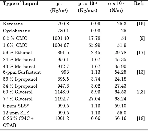
Iliuta and Thyrion [9] investigated the pressure drop for different CMC concentrations. Sai and Varma [10] and Larachi [11] presented different correlation in terms of Lockhart Martinelli parameters, flow variables and packing characteristics. Liquid holdup and two phase pressure drop are the two basic hydrodynamic parameters that are often inter linked with reaction conversion and selectivity, power consumption and interfacial mass transfer that take place in a trickle bed reactor [12]. The systems on which work has been already done experimentally, would enables to prior information to those fluids display foaming and aims significantly to what type of systems must need further researches. Therefore several attempts done to solve this problem, found in literature are listed below in Table 1. These authors reported that the values of two phase pressure drop for foaming systems are much lower than those prevailing with non foaming systems of close physicochemical properties under identical flow rates of both phases.
Past researches shows the dependence of decreasing surface tension with increasing foaming nature of listed systems. The Sodium Lauryl Sulphate used for present study produces a moderate to extensive foam formation ability depend upon concentration used and other parameters. Bansal [2], [3] produced very good correlation to predict foaming/pulsing transition regime by experimentation of 6 ppm and 12 ppm Sodium Lauryl Sulphate. Therefore to consider observations of past researches in a better manner and predict a more accurate correlation,
we used higher concentration of Sodium Lauryl Sulphate which also exhibits a similar physiochemical properties to chemicals listed in litera ture. During preliminary te sts, concentrations over 60 ppm showed a very intensive foaming and resulted into blockage, clogging and over flow within the reactor. Therefore present study is limited to four concentrations of 15, 30, 45 and 60 ppm aqueous solutions of Sodium Lauryl Sulphate along with water have been investigated in the form of more than 240 experiments. The impact of liquid and gas flow velocities, surface tension, gas density, solution concentration and particle diameter on the transition from trickle to pulse flow analyzed by change in two phase pressure drop and liquid rotameter to the top of the column and fed to the distributor. Experiments were carried out on a 10 Type of Liquid ρL
cm diameter glass column, packed with spherical glass beads of size 7.12 mm were provided at the top of the column. Air coming from the compressor via air surge tank was first saturated with process liquid in a saturator before introducing into the packed bed. This would avoid the effect of mass transfer between the gas and liquid phase inside the column. For the even distribution of liquid, a distributor was provided at the top of the packed section.
The liquid was introduced into the column at the desired air rate. Air is drawn from compressor trough pressure regulator. Solenoid valve in the air flow is provided so as to cut the supply of air instantly for the measurement of dynamic liquid saturation, air and liquid phase after transverse the length of the packing were discharged at the bottom of the column through a conical separator/discharger. Two quick closing solenoid
valve provided at the top of the column, one each in the air and liquid flow line facilitated in simultaneous cut off the phases when desired for holdup measurement. After start process, liquid concurrently down flow over packing. To check any leakage in the reactor the column exists at the bottom were closed. Manometer valve was also closed and air supply at 0.0312 kg/m2s
pressure was introduced. Now the setup was left in position for 30 minutes. The liquid flow was run for 20 minutes for complete wetting of the packing. Small quantity of air was now introduced into the column and slowly the airflow rate was brought to its desired rate within 2 3 minutes. Both the phases were allowed to flow downward over the packing for 20 25 minutes, which is necessary for the flow to attain a steady state. The flow pattern across the glass column was visually observed. The dynamic liquid saturation of the system was studied by drainage method. The inlet and outlet valve of the system were closed simultaneously. The liquid was collected in the column for 30 45 minutes till formation for stable foaming/pulsing flow at high flow rates.
3. Results and Discussion
Each set corresponds to reading at same air flow velocity whereas liquid flow rate is varied over a wide range of points in low as well as high interaction regimes. Solid packing of 7.12 mm glass beads, air flows of 0.0512 – 0.2559 kg/m2s
were used to investigate 15 ppm , 30 ppm, 45 ppm and 60 ppm Sodium Lauryl Sulphate – tap water solution (Table 2).
3.1. Effect of Liquid Flow Rate
On decreasing liquid flow rate, a uniform distribution persists in the form of trickle flow
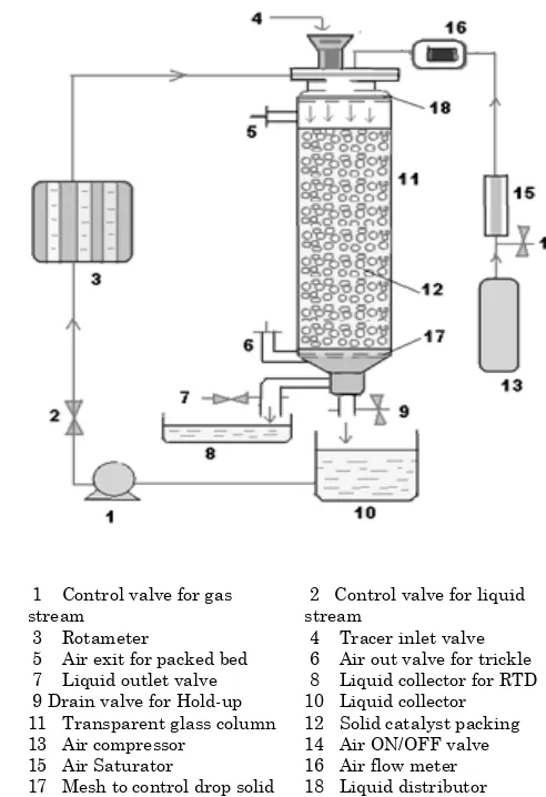
1 Control valve for gas stream
3 Rotameter
5 Air exit for packed bed 7 Liquid outlet valve
9 Drain valve for Hold up 11 Transparent glass column 13 Air compressor
15 Air Saturator
17 Mesh to control drop solid
2 Control valve for liquid stream
4 Tracer inlet valve 6 Air out valve for trickle 8 Liquid collector for RTD 10 Liquid collector 12 Solid catalyst packing 14 Air ON/OFF valve 16 Air flow meter 18 Liquid distributor
Figure 1: Experimental set up for present study of foaming liquids in trickle bed reactor
(GCF) is Figure 3. It maintains the continuous flow of film on the wetted and dry surface formed a uniform contact between liquid gas and solid particles for foaming liquids. This uneven flow of liquid and gas produces two low and high contact surfaces over packed bed in the form of two phase pressure drop during change of regime transition. High liquid side shear stress at the gas liquid and liquid solid interface leads to increases pressure drop with increase in surfactant concentration
For 15 and 30 ppm aqueous surfactant solution, the influence of liquid flow velocities on two phase pressure drop is more prominent at corresponding high gas flow rates. Further Figure 4 shows, for 60 ppm aqueous surfactant solution,
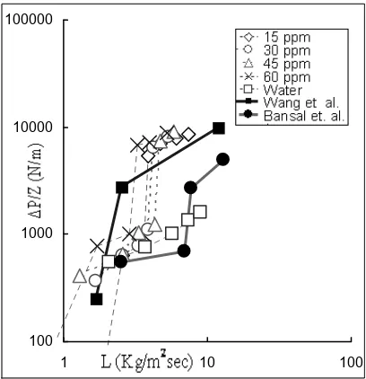
observed a significant increase in two phase pressure drop especially at low liquid flow rates. Further, Figure 5 presents the change in two phase pressure drop for different values of liquid flow velocities while comparing with past researches. The trends of high two phase
!
Type of Liq% uid Used
ρL (kg/m3)
.L x 10%3 (kg/m.s)
σ x 10%3 (N/m)
Water
15 ppm SLS *
30 ppm SLS 45 ppm SLS 60 ppm SLS
997.8 999.1 999.2 999.4 999.9
1.01 1.13 1.13 1.15 1.19
70.1 58.3 51.8 47.2 44.1 Table 2: Physical properties of chemicals used in study.
3 454 6 4 5 4
Figure 3: Effect of liquid flow rate on two phase pressure drop for 30 ppm Sodium Lauryl Sul phate
Figure 4: Effect of liquid flow rate on two phase pressure drop for 60 ppm Sodium Lauryl Sulphate
Figure 5: Full points are isoprpanol nitrogen sys tem at at σ = 27.43 N/m and G = 0.175 kg/m2s [13]
and 6 ppm surfactant air system at σ = 59.10 N/m and G = 0.225 kg/m2s [2], [3]. Empty points are
pressure drop in high interaction regime are similar to that reported by Wang [13] but lie significantly higher than the observations of Bansal [2], [3] in both low and high interaction regimes. From Figure 5, It is cleared that liquid flow rate have a strong effect on two phase pressure drop, and found 10 15% higher two phase pressure drop values than observations reported in literature. These fluctuations in results are possibly due to impact of foam formation during change of regime transition. Here more noticeable thing is effect of foam concentration is more prominent and significantly controls/changes the value of pressure drop in both trickle flow and foaming pulsing flow regime. 3.2. Effect of Gas Flow Rate
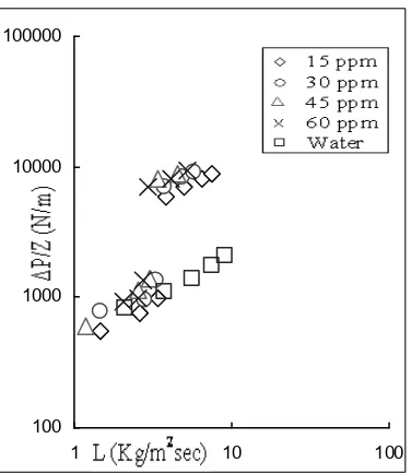
The dependence is not much similar to that observed for non foaming air water system (at 30º C) corresponds to low liquid and high air flow rates and vice versa (Figure 6). Surprisingly, the results observed are completely different to the foaming systems. Figure 7 confirms that the interaction between gas and liquid phases is small which leads to less prominent change in two phase pressure drop as compared to high gas flow rates. For 15 ppm aqueous surfactant solution, effect of gas flow rate is less prominent as compared to corresponding high gas flow velocities. It is observed that from Figure 8, at high gas flow rate of 0.2559 kg/m2s, two phase
pressure drop significantly increases in both low and high interaction regimes. The effect of gas
flow rate on two phase pressure drop is highly pronounced than that of liquid flow rates.
For present study, it is observed that the presence of the gas phase only reduces the available space for the flowing liquid. Investigation of 45 ppm and 60 ppm Sodium Lauryl Sulphate showed, at gas flow velocity of more than 0.1024 kg/m2s liquid flow may be
assumed uniform in each flow zone. Further with
"
Figure 6: Effect of liquid flow rate on pressure drop on non foaming water at gas flow velocities of 0.0512 – 0.2559 kg/m2s
Figure 8: Comparison of foaming aqueous solu tion of Sodium Lauryl Sulphate with non foaming water at air flow rate of 0.2559 kg/m2s
increase in liquid flow rate it behaved non uniformly in the form of pulsation and foaming over packed bed surface.
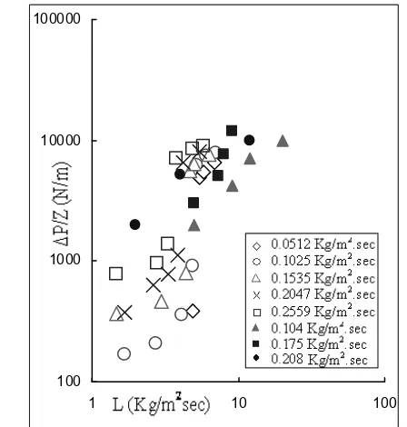
Figure 9 presents the comparison between the present investigations of 30 ppm aqueous solution of surfactant with literature listed researches. For foaming liquids, at a given liquid flow rates, the two phase pressure drop increased when the gas velocity was increased. Similar kinds of trendlines are observed by Wang [13] on gas flow rate of 0.208 kg/m2s and by Bansal [2], [3] at gas
flow rate of 0.104 kg/m2s and 0.175 kg/m2s for low
concentrations of surfactant nitrogen and surfactant air systems respectively. The trends observed by [2], [3] lies prominently lower than present investigation. Now it is crystal clear that, two phase pressure drop increases drastically with increase in gas flow rate during transition to trickle flow to pulsing foaming regime and impact is much pronounced as compare to liquid flow rate in downflow packed bed reactors.
3.3. Effect of Surface Tension
Trends from observations indicates, increase in pressure drop corresponding to excessive foam formation. Whereas for water, trends shows less prominent change in two phase pressure drop as
compared to foaming aqueous surfactant system was observed. The solution of low surface tension in the foaming pulsing flow regime produced much higher two phase pressure drop in
Figure 9: Full points are observations of 6 ppm sur factant air system at G = 0.104 kg/m2s and G =
0.175 kg/m2s by Bansal [2], [3]. Another full points
at G = 0.208 kg/m2s signifies the 6 ppm surfactant
nitrogen system by Wang [13]. Empty points are aqueous solution of 30 ppm surfactant air system at different gas flow velocities for present investigation
Figure 11: Full points are trends for 34% Isopro panol – nitrogen system with σ = 27.43 N/m and 40% Ethanol – argon system with σ = 31.88 N/m observed by Bartelmus [14], [15]. Trends with other full points signifies 6ppm surfactant – air system with σ = 59.12 N/m. Empty points are aqueous solution of surfactant – air system of different surface tensions at G = 0.204 kg/m2s
comparison to for non foaming water systems. It is regime at corresponding low liquid flow rates.
This clearly indicated that the decrease in and high interaction regimes.
For present investigation it is believed that the decrease in surface tension is associated with better spreading of the fluid. In trickle bed reactor lower surface tension or better spreading is expected to increased pressure drop. Figure 11 confirmed that, the influence of surface tension on pressure drop corresponds to different liquid Reynolds number is very significant while comparing high foaming liquids. The experimental points of present study lies lower than the trendline proposed by Bartelmus and Janecki [13], [14] which confirms that two phase pressure drop increases with increase in gas flow rate and decrease in surface tension.
For present study, foam generally starts occurred at liquid flow rate L = 4.022 kg/m2s.
Aqueous solution of 60 ppm surfactant produced heavy foam even at low liquid flow rate of L = 2.550 kg/m2s g which simultaneously leads to
heavy pressure drops values. This heavy change in two phase pressure drop values is depends upon concentration of foam (i.e. lowering of surface tension). It is verified by comparing results observed for presently studied air aqueous surfactant and air water systems.
4. Conclusions
For surfactant air systems, two phase pressure drop increases with an increase in liquid and gas flow rates. Change in gas flow velocities leads to significantly rapid increase in high interaction regime (FPF) as compare to low interaction regime (GCF). Studies of aqueous solution 60 ppm surfactant showed surprised results with sharp increase in reactor pressure drop even at very low liquid flow rate of 3.274 kg/m2s corresponds to gas
flow rate of more than 0.102 kg/m2se. The
possibility of foam formation in low surface tension solutions like 60 ppm aqueous surfactant solution under trickle flow conditions can not be ruled out. Hydrodynamics of pulsing flow in three phase fixed bed reactor operating at an elevated pressure, #
' 43: 4511–4521.
[2] Bansal, Ajay, 2003. Hydrodynamics of trickle bed reactor, & . Engineering and Technology Faculty, Punjab University, Patiala, Punjab, India.
[3] Bansal, A.; Wanchoo, R. K.; and Sharma, S. K. 2008. pattern, Pressure Loss and Liquid Holdup Data in Gas– Liquid Downflow Packed Beds with Foaming and Non foaming Hydrocarbons, )
) , 9: 350–356
[6] Saroha, A.K.; Nigam, K.D.P. 1996. Trickle bed reactors,
' + 1 12: 207–347.
Newtonian liquid systems, )
74: 783 796.
ρ
ρ
[10] Sai, P.S.T.; Varma, Y.B.G. 1987. Pressure drop in gas– liquid downflow through packed beds, %
# & ) 33: 2027–
2035.
[11] Larachi, F.; Laurent, A.; Midoux, N.; Wild, G. 1991. Experimental study of a trickle bed reactor operating at high pressure: two phase pressure drop and liquid
saturation. 4 46: 1233–
1246.
[12] Aydin, B.; Larachi, F. 2008. Trickle bed hydrodynamics for (non )Newtonian foaming liquids in non ambient
conditions, ) 143: 236–243.
[13] Wang, R.; Zai sha, M.; and Jiayong, C. 1995. Experimental and Theoretical Studies on Pressure Drop Hysteresis in Trickle Bed Reactors,
4 , 50(14): 2321 2328 .
[14] Bartelmus, G.; Janecki, D. 2004. Hydrodynamics of the cocurrent downflow of a gas and a foaming liquid through a packed bed. Part I. Estimation of the transition boundary between the hydrodynamic regimes from the gas continuous flow to the pulsing flow,
43: 169–179.
[15] Bartelmus G.; Janecki, D. 2003. Hydrodynamics of a cocurrent downflow of gas and foaming liquid through the packed bed. Part II. Liquid holdup and gas pressure
drop, 42: 993–1005.
[16] Charpentier, J. C.; and Favier, M. 1975. Some liquid holdup experimental data in trickle bed reactors for foaming and non foaming hydrocarbons. %
# ) 21: 1213
1218.
[17] Szlemp, D.; Janecki, A.; and Bartelmus, G. 2001. Hydrodynamics of a co current three phase solid bed reactor for foaming systems,
4 56: 1111 1116.
[18] Aydin, B.; Larachi, F. 2008. Trickle bed hydrodynamics for non Newtonian foaming liquids in non ambient
conditions. ) 143: 236 243.
[19] Gupta, R; and Bansal, A. 2010. Hydrodynamic Studies on a Trickle Bed Reactor for Foaming Liquids.
' 2 , 5 (1): 31