AJChE 2007, Vol. 7, No. 2, 120-126
Effects of Steam Injection Flow in Burner
and Outside Water Tube to the Increasing
of Boiler Temperature
M. Djoni Bustan
Departement of Chemical Engineering, Graduate School, University of Sriwijaya, Indonesia Padang Selasa Road No.524, Bukit Besar, Palembang 30139, INDONESIA
E-mail : [email protected]
Energy is an expensive basic need for human life, especially energy from fossils, such as crude oil, gas, and coal. In an oil refinery factory or electrical generator unit, where heat is most dominantly utilized, the boiler is used to generate steam. The main problem in a boiler is its uncompleted combustion process because of the incomplete ratio of air–fuel. This problem is caused by the addition of deposits or sealing inside and outside of the tube fire heater which will reduce the performance of fired heater. The objective of this research is to study the effect of steam flow variation on burner and tubing for increasing heat and temperature as well as the quality of steam. This research used a package boiler B& W series 1986 model which can be seen at an oil refinery factory or steam power electrical generator unit in Indonesia. This package boiler has 50kg/hours steam production capacity, qualified superheated steam, maximum pressure and temperature at 7kgs/cms2 and 700oC. Quantitatively, the achievable heat efficiency which corresponded to the temperature increase caused by the steam injection is 41.25% and the specific enthalpy is 12.07%.
Keywords: Boiler, carbon deposit, fired heater, and steam injection.
INTRODUCTION
The problem often encountered in a fired heater can be categorized into three types: operations, maintenance, and uncompleted heat transfer (ASME 1992). The major operation problem is uncompleted combustion caused by the incomplete ratio of air to fuel. This phenomenon will form a deposit or sealing outside and inside
of the tubes of the fired heater. Consequently, the quality of heat transfer from the burning energy to the fluids will be lower; hence, to handle these carbon deposits, the maintenance and operating costs of the fired heater get higher.
Berman’s “ How to Reduce Your Fuel Bill” (1978) offered some efficiency programs, such as an optimization program, to reduce the use of excess air and optimization of gas system
Paper13.indd 120
M.D. Bustan
121
to the liquid system for initial ignition in the furnace. Combustion reaction can be defined as the chemical reaction between oxygen and combustion compounds in fuel. The three components in fuel are carbon, hydrogen, and sulphur. It is a good combustion between combustion reaction and energy if all parts of the components are combusting to combustion reaction and all of the heat energy can be received by the fluid, with no heat loss discarded to the environment.
In the same year, Wilcox (1978) wrote in “ Improving Boiler Efficiency” his famous statements that “ boiler can produce more steam from less fuel if heat losses are minimized and combustion is optimized while downtime will be reduced with proper water quality.”
Before both publications, in 1970, Wiesenthal and Cooper wrote the scientific paper “ Guide to Economics of Fired Heater Design” along with the programming to optimize heater configuration, combustion air preheat, and design. On the other hand, also on fired heater efficiency, Frigoli (1999), determined the film of fuel deposited on the intake manifold of electroinjector engines with controlled ignition to United Stated patent number US00059579A.
Crude oil can be categorized into paraffin (CnH2n+2), aromatic (CnHn), and napthenic/ olefenic (CnH2n). Because of the dominant heavy oil that is used in Pertamina UP III Plaju is paraffin, the approach reaction mechanism of hydrocarbon compound with oxygen is shown by the following reactions.
CnHn+2 + O2 → CO + uH2O (1) spontaneously with hydrocarbon and hydrogen, starting from C20H42 until C20H42 so as to identify
the formation of carbon deposits. This research offered a way to handle the presence of deposits in the fired heater. It is through the steam injection system that carbon deposits stick to the wall outside the fired heater. The heat of the steam shot hot at a certain pressure results in carbon deposits. After the steam injection system was operated, the component that leaves will react with H2O according to the following reaction.
CnH2n+2 + H2O → u CO + v H2 (6)
Uncompleted combustion is caused by the deficient oxygen supply in the reaction. Next, the reaction will form carbon and form carbon deposits.
CO + H2 → C + H2O (7)
Carbon deposit must be reduced because it will cover the tube surfaces and make the heat transfer area smaller, decreasing the efficiency of boiler. Other factors that influence the combustion results are temperature, turbulence, and time: known as “ Three Ts of Combustion.” Carbon and hydrogen, which comprise the fuel, if burned completely will show the following reaction.
C + O2 → CO2 + 14.100 Btu/lb of C (8)
2H2 + O2→ 2H2O + 61.100 Btu/lb of H2 (9)
For this research, the fuel that will be used is heavy fuel oil consisting of some fractions such as outlined in Table 1.
Table 1. Heavy Oil Fractions
Fractions Boiling Point
(oC)
Atom Number C
Gasoline 30-210 5-12
Naphta 100-200 8-12
Kero & Jet Fuel 150-250 11-13
Diesel & Fuel Oil 160-400 13-17
Heavy Fuel Oil 315-540 20-45
Paper13.indd 121
122
Effects of Steam Injection Flow in Burner and Outside Water Tube to the Increasing of Boiler Temperature
EXPERIMENT
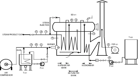
This research applied the mini-plant fired heater, Package Boiler model B& W 1986, that is used by oil refinery or Steam Power Electrical Generator in Indonesia. This mini-plant will operate to produce 50kg/hr of qualified superheated steam and a maximum pressure of 7 kg/cm2 and a maximum temperature of 700oC. The construction of the package boiler is made by scale up method to the real package boiler. The description of the package boiler is represented in Figure 1.
The combustion reaction is a reaction that occurs spontaneously and exothermically between fuel and oxygen. Two thermodynamics processes were observed in this research: combustion process and heat transfer process where, approximately, the convection was the dominant method in the heat transfer process. Deposit variables observed by few alternatives, such as the observed mass of flue gas from the stack and the deposited mass formed at combustion process using fuel references like fuel gas.
The main equipments are superheater tube bank, saturated tube bank, economizer, steam drum, burner, boiler feed water tank and pump, fuel oil tank and pump, and air compressor. This operation started by feeding boiler feed water using boiler feed water pump to the economizer, which worked using waste heat carried by the flue gas to the stack by the radiation of heat transfer. The fluids flowed to the steam drum with steam drum level at 70–80%. It flowed to the saturated bank and the superheated bank then heated by heat from the combustion reaction in the burner. The combustion reaction in the burner using heavy oil which was pumped by fuel oil pump from the fuel oil tank after reaching a heat of 70–80oC.
RESULTS AND DISCUSSION
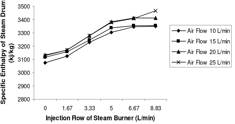
Steam injection as of the increasing amounts of air will influence heat efficiency. It can be seen in Figure 2 that the percentage of specific enthalpy increased from 1.67 to 6.67 L/min. The percentage increase of specific enthalpy caused by steam injection was 12.07%.
FI PI
Figure 1. Flowsheet of Fired Heater Boiler
Paper13.indd 122
M.D. Bustan
123
300 340 380 420 460 500 540 580
0 1.67 3.33 5 6.67 8.83
Injection Flow of Steam Burner (L/m in)
Steam Product Temperature (oC)
Air Flow 10 L/min
Air Flow 15 L/min
Air Flow 15 L/min
Air Flow 20 L/min
Figure 2. Injection Flow of Steam Burner (L/min) vs Steam Product Temperature (oC)
300 320 340 360 380 400 420 440 460 480 500
0 1.67 3.33 5 6.67 8.83
Injection Flow of Steam Burner (L/m in)
Steam Drum Temperature (oC)
Air Flow 10 L/min Air Flow 15 L/min Air Flow 20 L/min
Air Flow 25 L/min
Figure 3. Injection Flow of Steam Burner (L/min) vs Steam Drum Temperature (oC)
Paper13.indd 123
124
Effects of Steam Injection Flow in Burner and Outside Water Tube to the Increasing of Boiler Temperature
3000 3100 3200 3300 3400 3500 3600 3700 3800
0 1.67 3.33 5 6.67 8.83
Injection Flow of Steam Burner (L/m in)
Specific Enthalpy of Steam Product
(kj/kg)
Air Flow 10 L/min
Air Flow 15 L/min
Air Flow 20 L/min
Air Flow 25 L/min
Figure 4. Injection Flow of Steam Burner (L/min) vs Specific Enthalpy of Steam Product (kJ/kgs)
2800 2900 3000 3100 3200 3300 3400 3500
0 1.67 3.33 5 6.67 8.83
Injection Flow of Steam Burner (L/min)
Specific Enthalpy of Steam Drum
(kj/kg)
Air Flow 10 L/min
Air Flow 15 L/min
Air Flow 20 L/min
Air Flow 25 L/min
Figure 5. Injection Flow of Steam Burner (L/min) vs Specific Enthalpy of Steam Drum (kJ/kg)
Paper13.indd 124
M.D. Bustan
125
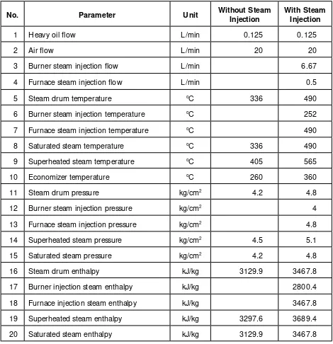
Table 2. Comparisons of Research Results
No. Parameter Unit Without Steam Injection
With Steam Injection
1 Heavy oil flow L/min 0.125 0.125
2 Air flow L/min 20 20
3 Burner steam injection flow L/min 6.67
4 Furnace steam injection flow L/min 0.5
5 Steam drum temperature oC 336 490
6 Burner steam injection temperature oC 252
7 Furnace steam injection temperature oC 490
8 Saturated steam temperature oC 336 490
9 Superheated steam temperature oC 405 565
10 Economizer temperature oC 260 360
11 Steam drum pressure kg/cm2 4.2 4.8
12 Burner steam injection pressure kg/cm2 4
13 Furnace steam injection pressure kg/cm2 4.8
14 Superheated steam pressure kg/cm2 4.5 5.1
15 Saturated steam pressure kg/cm2 4.2 4.8
16 Steam drum enthalpy kJ/kg 3129.9 3467.8
17 Burner injection steam enthalpy kJ/kg 2800.4
18 Furnace injection steam enthalpy kJ/kg 3467.8
19 Superheated steam enthalpy kJ/kg 3297.6 3689.4
20 Saturated steam enthalpy kJ/kg 3129.9 3467.8
Paper13.indd 125
126
Effects of Steam Injection Flow in Burner and Outside Water Tube to the Increasing of Boiler Temperature
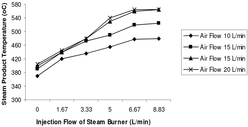
There was increase of temperature in all variations of air flow but the maximum of increase obtained was about 6.67L/min when injecting the steam for 1.66L and the average temperature was 40oC. The high increase in temperature was because of the heat resulting from the spontaneous reaction between carbon and steam at the furnace area and also from the reaction between fuel and steam at the burner which caused the decrease of carbon deposits forming in the combustion chamber. The minimizing of carbon in the combustion chamber gave good effect to the tube surface and enhanced the heat transfer. The maximum temperature steam product was about 565oC at the burner, steam injection at 6.67L/min, and 8.33L/min. The increasing of temperature efficiency caused by the steam injection reached 39.51%. The temperature increase in the steam drum gave the same pattern with the superheated steam product, but the maximum temperature achieved was lower than the superheated steam as shown in Figure 3.
To steam quality was identified by analyzing the specific enthalpy of steam products as can be gleaned from figures 4 and 5.
The steam product, superheated steam, is placed very close to the combustion chamber with higher temperature than steam drum flow or saturated steam with lower temperature. The increasing of steam enthalpy is very significant after injection by steam from 1.67 to 6.67 L/min for the steam product and steam drum. The steam injection of 1.66L/min will increase the enthalpy to 98.18kJ/kg for steam product and to 69.35kJ/ kg for steam drum; in contrast, before 8.33L/min of steam injection, the increase of enthalpy was constant.
CONCLUSIONS
Heat enhancement in the furnace through steam injection results in a 41.25% percentage increase in achieved temperature, a 12.07% increase in specific enthalpy, and 13.48% fuel savings. The steam injection system also can reduce the thickness of carbon deposits attached to the superheater tube walls by about 94.5%.
REFERENCES
Azharuddin, and Bustan, M.D. (2006). “ Effects of Steam Injection Flow to the Increasing of Boiler Temperature” . Thesis. University of Sriwijaya, Palembang, Indonesia.
Agustin G.T. (1975). “ Shreve’s Chemical Process Industries”. Washington State University, Mc Graw Hill Book Company. USA.
ASME Boiler and Pressure Vessel Committee. (1992) “ ASME Section I--Rules for Construction of Power Boiler.” The American Society of Mechanical Engineers, New York.
Babcock and Wilcox Co. (1975). Steam, Its Generation and Use. 38th Edition. New York, USA.
Berman, H. (1978). How to reduce your fuel bill, “ Fired heaters–IV,” Chem. Engng,165-169.
Frigoli, A., Livraghi, G., and Mioralli. (1999). “ Process for Determining the Film Off Fuel Deposit on the Intake Manifold of Electroinjector Engines With Controlled Ignition” . US Patent, US005957993A. McCain, William D. (1990). The Properties of
Petroleum Fluids. 2nd ed. Penn Well Books, Tulsa, OK.
Smith, C.B. (1981). Energy Management Principles, Application Benefits Savings. Pergamon Press.
Wilcox, J.C. (1978). “ Improving boiler efficiency,” Chem. Engng., 85 (Oct 9), 127.
Paper13.indd 126