Application of Sliding Mode Control in Indirect Field Oriented
Control (IFOC) for Model Based Controller
Angga Wahyu Aditya, Dedid Cahya Happyanto, Bambang Sumantri
Politeknik Elektronika Negeri Surabaya / PENS
Jl. Raya ITS – Kampus PENS Sukolilo, Surabaya Telp. (+62) 31 594 7280 [email protected], [email protected], [email protected]
Abstract
Indirect Field Oriented Control (IFOC) is one of the vector control methods that can be applied to induction motor in the industrial world rather than Direct Field Oriented Control (DFOC) because of the flux is obtained from the formulation. However, IFOC can not guarantee the robustness and stability of the systems. Stability analysis such as Lyapunov Stability Theory can be used to make the system stable but not the robustness. Model based controller that can guarantee the stability and robustness such as sliding mode control (SMC) and fuzzy needs to be added in IFOC system to achieve proportional response system. Robust current regulator using sliding mode control was designed in this paper from state space model for model based controller. In transient response and under disturbance SMC shows better performance than PID in rising time and robustness at rotor speed and stator current.
Keyword : IFOC, Induction Motor, State Space Equation, Model Based Controller, SMC.
[3], [4]. However, IFOC cannot guarantee robustness and stability aspect of the systems. Robustness and stability aspects must be added to achieve high-performance of the system. The analytical stability such as Lyapunov Stability Theory can guarantee the stability of the system but not the robustness.
Model based controller such as fuzzy [5], [6] and sliding mode control (SMC) [7], [8] can be designed to guarantee robustness, stability and optimal condition of the system. State space equation should be modelled to determine the architecture of the controller such as fuzzy and SMC. The IFOC state space equation is obtained from the modeling of the induction motor at DQ rotating frame by making the flux on the d-axis to be constant and the q-axis to zero [3]. This paper is organized as follows. Section 2 describes about related research with this issue. The originality of this paper is shown in section 3. Section 4 describes per unit induction motor model in the rotating frame with arbitrary speed. The way to get IFOC equation from induction motor model in DQ reference frame is described in section 5. In section 6, the IFOC equations that consist of speed, flux, and current regulator equation is modeled to state space can be used to design the model based controller. in section 7, IFOC – SMC design is proposed to make response system robust and stable. Result and discussion about rotor speed and current regulator response in IFOC state space are described in section 8. Finally, the conclusions of this paper are shown in section 9.
2. RELATED WORKS
I F O C is one of the vector control methods that separate torque and flux in the induction motor. This technique represents the complex and nonlinear model of induction motor in a similar manner to DC machines to get high-performance control [3]. The basic characteristic of flux, speed and stator current of IFOC need the controller to perform good characteristic, guarantee robustness and stability .
The model based controller like fuzzy model based and sliding mode control need a state space model to generate controller design. The state space model can be used to determine the stability condition using stability theory such as lyapunov and the constant of robustness to perform proportional response system [9].
Research about the robust controller for speed regulation using sliding mode for IFOC system already exists. In this research, the sliding mode controller is designed in speed regulation to guarantee the robustness in rotor speed aspect [10]. This paper proposed the design of IFOC state space for induction motor in a current regulator. The state space can be used to design the suitable controller that guarantee robustness, stability, and high-performance in dynamic response. The sliding mode is designed in current regulator side to guarantee the robustness in speed response.
This paper contribution is designing sliding mode control (model-based controller) for IFOC which applied for an induction motor. The sliding mode is designed in current regulator side to achieve the robustness, stability and reach the optimal condition in proportional time of rotor speed. The chattering phenomenon in rotor side should be avoided because of its danger to the hardware and consume more energy. By designing SMC in current regulator, the chattering phenomenon in rotor speed can be eliminated but not the robustness and stability.
4. INDUCTION MOTOR MODEL
Per phase of induction motor’s equivalent circuit consist of stator and rotor side resistance, leakage inductance, induced voltage and mutual inductance shown in Figure 1.
Fig. 1. Per phase equivalent circuit of IM
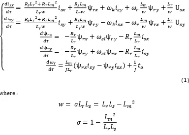
The induction motor model presented in the rotating frame with arbitrary reference speed is [3], [11] :
U is voltage and i is current of stator vectors; ψ is flux of rotor vectors ( , are real and imaginary axis); is rotor angular speed; is slip angular speed; is angular speed of reference frame; is load torque and is relative time [11].
5. INDIRECT FIELD ORIENTED CONTROL (IFOC)
From induction motor model in equation 1, electrical induction motor model in dq rotating frame is [3], [12]:
=
−
+
+
+
+
The mechanical modeling from equation 1 is given by :=
(ψ
− ψ
) +
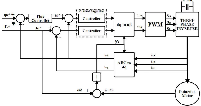
(3)Indirect field oriented control of induction motor’s principle is that dq rotating frame is connected to the rotor flux vector. So, the flux and torque can be controlled separately by stator direct-axis current ( ) and quadrature-axis current ( ) shown in Figure 2. This form takes the control of an induction motor looks like separately-excited DC motor in linearity control, decoupling and high performance [11], [13], [14].
The field oriented control orientation is obtained by [3], [12] :
=
= 0
(4)The current regulator equation can be defined by substitution equation (4) to equations (2) :
=
−
+
+
+
=
−
+
+ (
) +
(5)=
2
3
cos( ) cos( − 120
°
) cos( + 120
°)
sin( ) sin( − 120
°) sin( + 120
°)
0.5
0.5
0.5
with :
= (
+
)
where , is rotor and stator angular speed of induction motor [10]. The rotor flux in direct axis based on equation 2 substituted to equation 4 is :
=
−
(6)equation 6 can be write :
ψ =
1 +
and the quadrature rotor flux is :
0 =
+
− 0
(7)the mechanical equation substituted from equation 3 to equation 4 is :
=
(ψ
) +
(8)the electromagnetic torque is [11], [15] :
T =
(ψ
)
(9)Fig. 2 Indirect field oriented control scheme 6. CURRENT REGULATOR STATE SPACE MODEL OF IFOC
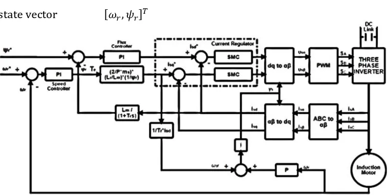
The state space of IFOC shown in Figure 3 uses multiloop model (decoupled / cascade system) which consists of two loops. The inner loop is stator current regulator and the outer loop is rotor flux and speed controller. The state space model of IFOC’s current regulator is :
̇ =
+
+
(10)
The outer loop equations are rotor flux and speed as in equation 6 and 8 with :
state vector [ , ]
Fig. 3 Blok diagram of decoupled indirect field oriented control scheme for model based controller
7. IFOC – SLIDING MODE CONTROL DESIGN IN CURRENT REGULATOR
The sliding surface is presented by [16] and [17] :
(
e
; ) =
+
λ
1
e
where n is degree of sliding surface; e= − is error and λ is constant. The strategies to design sliding mode control is as follows :
=
+
(11)Lyapunov function used to gurantee the system stability is : = 1 2 2
this lyapunov function has derivative : ̇ = ̇ with :
= λe
̇ = λė
From equation 10, 11 and Lyapunov stability function, the current regulator controller is :
=
1̇
−
−
(12)1
=
0
0
where 1 is the inverse of matrix B; ̇ is the differential desire state vector of current regulator state space.
= +
[ ]
(13)By substituting equation 12 and equation 13 to equation 11, the sliding mode control design is :
=
1̇
−
−
+ +
[ ]
The stator current regulator in D-axis is :
(
) =
̇
+
−
−
+ [
S
] +
[
S
]
The stator current regulator in Q-axis is :
=
̇
+
−
−
+ [
S
] +
[
S
]
8. RESULT AND DISCUSSION
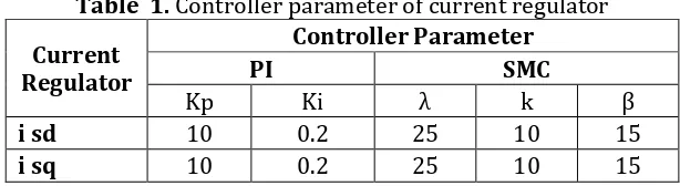
The proposed model based controller in current regulator side of IFOC for robustness and stability controller using SMC is compared with PI controller in variable rotor speed and stator current in DQ rotating frame that shown in Figure 3. By making the same controller and its parameter in speed and flux controller the performance of a model based controller can be compared with PI controller in a current regulator. The parameter controller of current regulator is shown in Table 1. In transient response of 900 rpm of rotor speed shown in Figure 4, the PI controller has 62.17 ms of rising time, 1.97 ms of undershoot and 0.5 % overshoot. The SMC has 6.76 ms rise time and 0.5 % overshoot. In achieving a reference speed SMC, gives a better response than PI controller with rising time less than 8 ms shown in Table 2 and 3. The performance of SMC and PI controller in overshoot and undershoot side are nearly same.
Table 1. Controller parameter of current regulator
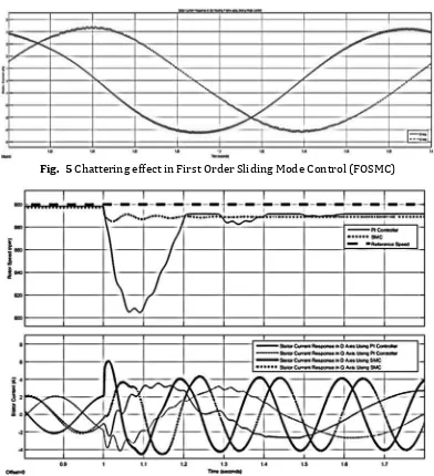
The robustness and stability of model-based controller using SMC to overcome the disturbance is shown in Figure 4 with 1.5 Nm of torque load ( ). In SMC, the speed response in overcoming the disturbance is decreasing but less than 2 % of steady state error in reference speed 900 rpm. The robust model-based controller in multiloop IFOC system designed in current regulator using First Order Sliding Mode Control (FOSMC) that contains chattering phenomenon in Figure 5. The comparison between model-based and PI controller proven that model-based controller such as SMC is better in overcoming the disturbance like in Figure 6.
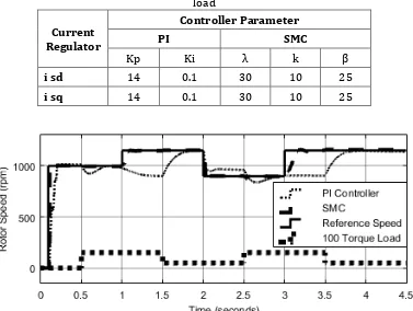
In Figure 7, the rotor speed response of IFOC method which uses PI controller and SMC is compared in variable reference speed and torque load. Controller parameter which uses these results are shown in Table 4. The results show that SMC controller can compensate the disturbance but not the PI controller. When the rotor speed is under 1.5 Nm disturbance at 0.5 seconds, SMC controller can compensate the disturbance (robust) but not for PI controller. When the reference speed is changed in to be 1.150 rpm and is under disturbance, the SMC controller shows the robustness but PI controller is not. The PI controller reaches the reference speed again when the torque load decrease to 1.5 seconds. This condition repeats in 2 and 2.5 ; 3 and 3.5 seconds.
Table 2. First comparison of PI controller and SMC in transient response
Reference Speed (rpm) 700 800 900
Transient Parameter PI SMC PI SMC PI SMC
Rise Time (ms) 52.04 4.55 57.30 4.90 62.17 6.76
Overshoot (%) 3.65 2.58 0.5 1.53 0.5 0.5
Undershoot (ms) 1.97 8.51 1.99 1.94 1.97 1.89
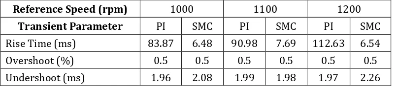
Table 3. Second comparison of PI controller and SMC in transient response
Reference Speed (rpm) 1000 1100 1200
Transient Parameter PI SMC PI SMC PI SMC
Rise Time (ms) 83.87 6.48 90.98 7.69 112.63 6.54
Overshoot (%) 0.5 0.5 0.5 0.5 0.5 0.5
Fig. 4 IFOC’s rotor speed response using PI controller and SMC under disturbance at 1 second and reference rotor speed at 900 rpm
Fig. 5 Chattering effect in First Order Sliding Mode Control (FOSMC)
Table 4. Controller parameter of current regulator for variable speed and torque load
Current Regulator
Controller Parameter
PI SMC
Kp Ki λ k β
i sd 14 0.1 30 10 25
i sq 14 0.1 30 10 25
Fig. 7 The comparison between PI and SMC controller in variable reference speed and torque load
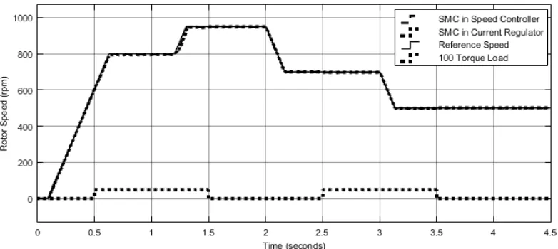
Fig. 8 Variable speed response using SMC in Speed controller and Current Regulator with various torque load
Fig. 9 Chattering phenomenon in Speed Response
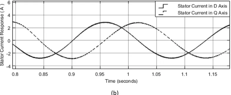
(b)
Fig. 10Stator Current Response in DQ rotating frame (a) SMC in speed controller (b) SMC in current regulator
Table 5. Comparison table of SMC in speed controller and current regulator
Stator Current (A) In D Axis In Q Axis SMC in Speed
Controller 2.96 3.00 SMC in Current
Regulator 2.79 2.77
9. CONCLUSSION
10. ACKNOWLEDGMENTS
The authors would like to thank “Allah SWT” who has provided affection and ease in research. In second place, spesial thanks to parents, brother and sister for support and pray. Then thanks to Electric Machine and Control Laboratory – Politeknik Elektronika Negeri Surabaya (PENS).
11. REFERENCES
[1] A. V. R. Teja, V. Verma and C. Chakraborty, “A New Formulation of Reactive Power Based Model Reference Adaptive System for Sensorless Induction Motor Drive,” IEEE TRANSACTIONS ON
INDUSTRIAL ELECTRONICS, vol. 62, no. 11, pp. 6797 - 6808, 2015.
[2] B. K. Bose, Modern Power Electronics and AC Drives, Prentice Hall, 2001.
[3] H. Abu-Rub, A. Iqbal and J. Guzinski, High Performance Control of AC Drives with MATLAB/Simulink Models, West Sussex: John Wiley & Sons Ltd, 2012.
[4] Y. B. Zbede, S. M. Gadoue and D. J. Atkinson, “Model Predictive MRAS Estimator for Sensorless Induction Motor Drives,” IEEE
TRANSACTIONS ON INDUSTRIAL ELECTRONICS, vol. 63, no. 6, pp.
3511-3521, 2016.
[5] Y.-H. Joo and L.-S. Shieh, “Hybrid State-Space Fuzzy Model-Based Controller with Dual-Rate Sampling for Digital Control of Chaotic Systems,” IEEE Transactions on Fuzzy Systems, vol. 7, no. 4, pp. 394 - 408, 1999.
[6] A. Kroll, T. Bernd and S. Trott, “Fuzzy Network Model-Based Fuzzy State Controller Design,” IEEE TRANSACTIONS ON FUZZY SYSTEMS, vol. 8, no. 5, pp. 632 - 644, 2000.
[7] B. Sumantri, Robust and Energy-Efficient Controller Design for a Quad-Rotor Helicopter, Aichi: Toyohashi University of Technology, 2015.
[8] O. Barambones and P. Alkorta, “Position Control of the Induction Motor Using an Adaptive Sliding Mode Controller and Observers,”
IEEE TRANSACTIONS ON INDUSTRIAL ELECTRONICS, vol. 61, no. 12, pp.
6556 - 6565, 2014.
NonlinearSliding Surface,” Journal of Systems Design and Dynamics, vol. 7, no. 2, pp. 226-241, 2013.
[10] N. M. Noaman, “Speed Control for IFOC Induction Machine with Robust Sliding Mode Controller,” Asian Journal of Scientific Research, vol. 1, no. 4, pp. 324-337, 2008.
[11] B. M. Wilamowski and J. D. Irwin, Second Edition : The Industrial Electronics Handbook - Power Electronics and Motor Drives, CRC Press, 2011.
[12] N. P. Quang and J.-A. Dittrich, Vector Control of Three-Phase AC Machines, Berlin: Springer-Verlag Berlin Heidelberg, 2015.
[13] I. Ferdiansyah, E. Purwanto and N. A. Windarko, “Fuzzy Gain Scheduling of PID (FGS-PID) for Speed Control Three Phase Induction Motor Based on Indirect Field Oriented Control (IFOC),” EMITTER
International Journal of Engineering Technology, vol. 4, no. 2, pp.
237-258, 2016.
[14] R. Fauzi, D. C. Happyanto and I. A. Sulistijono, “Fast Response Three Phase Induction Motor Using Indirect Field Oriented Control (IFOC) Based On Fuzzy-Backstepping,” EMITTER International Journal of
Engineering Technology, vol. 3, no. 1, pp. 92-114, 2015.
[15] P. Krause, O. Wasynczuk, S. Sudhoff and S. Pekarek, ANALYSIS OF ELECTRIC MACHINERY AND DRIVE SYSTEMS, New Jersey: John Wiley & Sons, 2013.
[16] C. M. R. Oliveira, M. L. Aguiar, J. B. Monteiro and W. C. Pereira, “Vector Control of Induction Motor using a Sliding Mode Controller with Chattering Reduction,” IEEE Brazillian Electronics Conferrence and 1st
Southern Power Electronics Conferrence (COBEP/SPEC), Fortaleza, 2015.