A Wireless Clinical Thermometer for Frequent Baby Monitoring
Daniel Santoso a, Roderick Yap a,Wen-Yaw Chung a, and Yuh-Show Tsai b*
a
Department of Electronic Engineering, bDepartment of Biomedical Engineering Chung Yuan Christian University, 200 Chung Pei Rd., Chung Li, Taiwan 32023, R.O.C
*Correspondence: [email protected]
Abstract
For babies under 1 year old running at high fever, frequent monitoring of body temperature can help immediately alert the parent or the doctor when the temperature reaches the critical level. To maximize efficiency of the doctor or the parent in relation to his other tasks, monitoring can be done at a distance using wireless transmission of temperature. This paper describes the design of a wireless clinical thermometer for frequent baby monitoring. The design makes use of JA31104 clinical digital thermometer as sensor. The sensor is interfaced to a standard 8051 compatible microcontroller chip which encodes the information from the sensor and subsequently sends it serially to a CC2500 wireless transceiver chip. The microcontroller at the transmitter side regulates the timing of data acquisition and shuts off the power from the sensor at regular time intervals. The data received from the wireless transmission is then displayed on the PC to be analyzed and the performance of the system is evaluated. Keywords: Thermometer, Wireless, Microcontroller.
1. Introduction
Healthcare services have become a target application for a number of wireless technologies. Going wireless in healthcare services can offer a lot of advantages. Some of these include patients’ medical record electronically recorded /updated and sent to the doctor at any time and anywhere [5]. Medical equipment / sensors that operate wirelessly can be as mobile as the patient himself. This eliminates the need to disconnect and reconnect the equipment by hardwire to the network every time the patient is moved or relocated to another area [5]. The Bluetooth technology for instance, is a popular wireless technology employed for many electronic products such as cell phones and laptops. In medical applications, Bluetooth is also common when it comes to wireless ECG applications [8] [9]. In one study [6] however, the limitation of Bluetooth can be realized when it comes to supporting topologies consisting of multiple medical sensors. This is due to its limitation of 7 slaves in one Piconet [6].
IEEE 802.15.4 is another wireless technology known for its limited battery power consumption [6]. In one study [7], various sensors intended for body implant were tested in terms of its battery lifetime. Data from the sensor were supposed to be obtained wirelessly. IEEE 802.15.4’s low power consumption feature was adopted for obvious reasons that one cannot randomly replace sensor battery once it has been implanted inside the human body. Experimental result shows a possible battery lifetime that can last up to at least 15 years when the non-beacon type of network is employed for this
technology. In a separate study [6], when multiple sensors are used, packet loss can be a problem. This drawback of IEEE 802.15.4 can be attributed to its limited bandwidth and Medium Access Control (MAC) protocol designs [6].
Recent RF transceivers like the CC2500 have provided an alternative for medical wireless applications. CC2500 is a Low-Cost Low-Power 2.4 GHz RF Transceiver developed by Texas Instrument [4]. It supports a configurable data rate of up to 500 kbps. The device boasts of its low current consumption at 13.3mA. When compared to the ML7050LA Bluetooth RF Transceiver, CC2500 consumes much lesser current [4][10]. In this paper, we will explore the use of CC2500 transceiver for our wireless clinical thermometer.
The JA31104 CMOS digital clinical thermometer is known for its measurement accuracy of up to ± 0.1C [1]. Its features include automatic power off, highest temperature hold and multi stable time selection among others [1]. While the device can be readily interfaced to an LCD for immediate display of acquired temperature, its other output pins such as OEB and DATA make it a flexible device for microcontroller interfacing. This can serve as a means for wireless transmission of data. The flowchart algorithm provided in the JA31104 thermometer data sheet, shows how the circuitry inside the device provides sufficient intelligence to enhance accuracy of data. The device is programmed to display the highest value acquired for a given sampling period. Furthermore, it is self-equipped with its own timing regulation for updating any changes in temperature and even for shutting off the device. Referring to the datasheet, the chip is designed to process the raw temperature information from thermistor typed 503ET. This type of thermistor has sensing range from -40 oC to 100 oC with 50kΩ resistance measured at room temperature. The resistance variation is further processed by JA31104, but since the chip is intended for clinical use, the temperature sensing is limited to 32 oC to 42.99 o
C.
service inside the microcontroller device. The Serial Peripheral Interface (SPI) of the device is a high speed serial communication interface. It is capable of full duplex operation with up to 3 Mbits per second supported in either master or slave mode [3].
Measuring body temperature has many alternative ways. Measuring method can be rectal, ear, oral, axillary (armpit) or temporal artery (forehead) [13]. Due to heat loss from uncovered part of the body, forehead temperature is usually lower than that of the covered part of the body [13]. Normal forehead temperature ranges from 35oC to 38oC [13]. When the body temperature drops considerably to a low level below the normal range, the patient suffers from hypothermia [12]. On the other hand, when body temperature rises above the normal range, the patient is said to suffer from fever [11].
2. Design Consideration 2.1. System overview
Shown in the figure 1 is the overall block diagram of the system.
Figure 1. Overall block diagram
Data from the sensor is encoded by the microcontroller (MPC82G516A) into a human readable form. This data is then transmitted serially to the RF transceiver (CC2500). The transceiver transmits the data wirelessly. The data is then received by the RF transceiver in another side. Similar to the transmitter side, the data from the RF transceiver at the receiver side is fed to the microcontroller to be sent to the PC using UART port. The microcontroller in the receiver side serves as bridge between PC and the RF transceiver since the only possible access to the RF transceiver is through the SPI (Serial Peripheral Interface) which is normally not available in the PC.
2.2. Thermometer chip-MCU interface
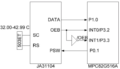
As seen from figure 2, the sensor is linked to the microcontroller through its OEB pin, DATA pin, and PSW pin.
Figure 2. Temperature chip and MCU connection
Referring to JA31104’s data sheet, the OEB is the sensor’s timing indicator for sampling of data. A low logic at OEB means the sensor is measuring the temperature. A high OEB indicates a readily available temperature data that can be acquired by the microcontroller unit. The sensor’s DATA pin is a series of clock pulses that occur during temperature measurement routine. The number of clock pulses that emanates from the DATA pin corresponds to a particular temperature reading. The DATA and OEB waveforms are clearly illustrated in figure 3 [1].
Figure 3. DATA and OEB timing
The OEB signal fed to the microcontroller is used as external source interrupt for the microcontroller to periodically acquire temperature data from the sensor. But because the availability of data occurs during the rising edge of the OEB and at the same time the external interrupt pins are active low, an inverter has been used to yield an /OEB. The microcontroller divides the sensor’s operation into 2 external interrupt stages: the data generation stage and the data acquisition stage. During the falling edge of OEB i.e. data generation stage, a timer inside the MCU is activated. Pulses from the data pin are used to increment the timer. During the falling edge of /OEB i.e. data acquisition stage, the timer value is decoded into a human readable format of temperature data. Hexadecimal to Binary Coded Decimal conversion and an additional 1st digit correction procedure are carried out prior to preparing data for transmission.
PSW is another input pin to the temperature sensor. A pulse applied to this pin alternately turns on and turns off the sensor. In order to conserve power, the microcontroller outputs a periodical 200 ms pulse to turn the sensor ON when measurement is needed and subsequently turn it OFF after measurement.
2.3. Wireless transceiver chip-MCU interface
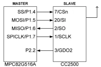
The RF transceiver chip CC2500 is configured via a simple 4-wire SPI compatible interface (SI, SO, SCLK and CSn) where CC2500 is the slave. This interface is also used to read and write buffered data. All address and data transfer on the SPI interface is carried out beginning with the most significant bit as the first to be transmitted or received. There is one more additional pin used in this application that is GDO2. It is configured as a flag to notify the microcontroller when one data packet is completely transmitted / received. The SPI speed is configured at 86.4 kHz. The connection diagram is shown in figure 4.
Figure 4. MCU and transceiver chip connection
All transactions on SPI interface start with a header byte containing a read/write bit, a burst access bit and 6-bit address. The timing for the address and data transfer on SPI interface is shown in figure 5 [4].
Figure 5. Registers write and read operations
Basically, there are five types of registers that can be accessed by the microcontroller. These are chip status register, configuration registers, command strobes registers, FIFO registers, and PATABLE register. The chip status byte contains key status signals, useful for the microcontroller. The configuration registers provide access to configure the various properties of CC2500. By addressing a command strobe register, internal sequences will be started. These commands are used to enable transmit mode, receiver mode, idle mode, reset chip, etc. The transceiver chip incorporates 64-byte TX FIFO and 64-byte RX FIFO. When the read/write bit is zero, the TX FIFO is accessed and vice versa. The PATABLE register is used for selecting PA power control settings.
2.4. Transmitter section
The transmitter section consists of three chips namely the clinical thermometer (JA31104), microcontroller unit (82G516A), and RF transceiver (CC2500). Principally, this configuration enables the thermometer chip to transmit its data wirelessly. The connection diagram is shown in figure 6.
Figure 6. Transmitter connection diagram
The transmitter section is designed to be battery powered since all of the components are low-power devices. The voltage requirement is 3 V, therefore two AA-size batteries connected in series is suitable for this application. The core of this section is the MCU, it is responsible for regulating the data acquisition and transmission. The data acquisition is not performed in continuous mode since it is not necessary to collect the body temperature in very close time intervals. In this application, the data acquisition is only performed every 14 minutes with 1 minute duration. It is necessary to perform continuous reading within 1 minute since the thermometer chip requires a number of seconds before temperature data stabilizes. This switching mechanism is illustrated in figure 7.
Figure 7. Data acquisition timing
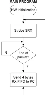
During 1 minute “on” period, the temperature data will be available every 0.5 second, therefore exactly every 0.5 second, the temperature data in the microcontroller’s internal memory will be updated. The program flow of the microcontroller is illustrated in figure 8.
Figure 8. Program flow on transmitter section
the transceiver chip and wait until the end of packet. After one packet is successfully sent, the transceiver chip will enter the “IDLE” state and microcontroller waits for new data.
The transceiver chip has its own packet format. Nevertheless, this format is configurable to accommodate various applications. The packet format used in this application is illustrated in figure 9.
Figure 9. Packet format
The payload is carried in the “Data field” slot, consisting of four bytes. This is illustrated in figure 10.
Figure 10. Payload format
From figure 10, it is obvious that temperature data is represented in two bytes, the first byte is the integer part while the second byte is the fractional part. All are in the two digits BCD format. The operation status of the thermometer chip is also appended on the last byte. “On” state is indicated by “0xFD” while “Off” state is indicated by “0xFF”.
The packet is transmitted wirelessly at 2433 Mhz frequency using MSK (Minimum Shift Keying) modulation, with data-rate 250 kbps. The output power of RF transceiver is set at -11.8 dBm.
2.5. Receiver section
The receiver section is almost similar to the transmitter counterpart. It consists of RF transceiver (CC2500), microcontroller unit (82G516A), and a PC which is used to provide graphical interface to the user. The connection diagram is shown in figure 11.
Figure 11. Receiver connection diagram
The receiver section is more flexible than the
transmitter counterpart. It doesn’t have to be battery-powered since it always attached to the PC. This section can draw the power from PC’s USB port since it is equipped with 3.3 V voltage regulator. The core of this section is the MCU, which is responsible to communicate with the transceiver chip to obtain the data and pass it to the PC. The program flow in this section is also simpler. Most of the time the transceiver stays in the RX mode to wait the incoming data packet. As soon as one data packet has completely arrived, the microcontroller will copy the RX FIFO content from the transceiver chip into the internal memory and pass it to the PC through UART port. The program flow is illustrated in figure 12.
Figure 12. Program flow on receiver section The program in the PC plays more important role in this section. The interface between user and the system is provided in this graphical interface. This interface is developed using Visual Basic 6. Figure 13 shows the interface window at the receiver side.
Figure 13. Receiver interface window
The description of each function on the interface window is listed below:
1. date and time when last stable temperature data acquired,
2. temperature reading, 3. temperature unit option, 4. serial port open / close button, 5. reset button in case of fever detected, 6. close program button,
8. Patient status based on the body temperature. As aforementioned previously, the data acquisition is only performed every 14 minutes with 1 minute duration. During the data acquisition, the system message window will display “Acquiring…” message until temperature reading is stable. As soon as the data acquisition is completed, the temperature reading and time indicator freezes, indicating the last stable value. At the same time, the “Stable” message will be displayed on system message window. In case of fever i.e. temperature detected is greater than or equal to 37.8 oC, an audible warning will be produced through PC’s soundcard. The warning can only be silenced by pushing the reset button on the window. If the detected temperature is lower than 32 oC the system message window will display the “Check the sensor” message. This will notify the user to make sure that the thermistor is properly attached to the forehead.
3. Analysis of Results
The system is designed to perform frequent temperature monitoring wirelessly. During experimentation, the system is operated for approximately 2 hours continuously, the receiver is distanced 5 meters from the transmitter, and the thermistor is attached on the forehead of the subject. The temperature readings are summarized in table1.
Table 1. Summary of the experiment Time Temperature (oC) Status
10:35:02 35.60 Normal 10:48:42 35.62 Normal 11:02:21 35.66 Normal 11:16:01 35.63 Normal 11:29:40 35.71 Normal 11:43:20 35.77 Normal 11:59:59 35.75 Normal 12:13:38 35.75 Normal
Based on the observation from the user interface window, the data transmission is smoothly received and displayed. There is no deviation detected. The temperature readings indicated by table 1 for about 2 hours are also stable without any significant fluctuation.
In order to examine abnormal scenarios, two experiments have been conducted. First, the thermistor is detached from the forehead so temperature reading drops below 32 oC. At that time, the “Check sensor” message is displayed on the system message window. The captured user interface window is shown in figure 14.
Figure 14. User interface window in case of thermistor detached
Secondly, in order to evaluate the warning mechanism in case of fever, the thermistor is placed near a glass of hot water so the temperature reading rises above 37.8 oC. At that time, an audible warning is produced through PC soundcard to the external speaker. This forces the user to pay attention on the cause of the alarm. The captured user interface window is shown in figure 15.
Figure 15. User interface window in case of fever detected
The current consumption is also measured on the transmitter section. During the “On” state, using 3 V power supply, the total current consumption is 3.24 mA. Assuming that the transmitter section will be powered by 1000 mAh rechargeable batteries, it will have approximately 300 hours operating time.
4. Conclusion and Future Work
A prototype of wireless clinical thermometer for frequent baby monitoring has been successfully developed and evaluated.
Most of the components employed are from low-power series; therefore the current consumption is also considerably low during operational state. The distance between transmitter and receiver can be up to 5 meters and the battery life is expected up to 300 hours.
diverse requirements. This mode also gives advantage to the transmission range. By implementing particular algorithm to the system, the transmitter side and receiver side can automatically adjust the RF power to obtain optimum transmission range. This successful result also pave the way to the automatic patient data logging based on the PC, which can improve health service performance.
5. References
[1] JA31102/JA31103/JA31104/JA31105
Two-Decimal Clinical Thermometer Datasheet, version 1.5.
[2] I. Scott MacKenzie, The 8051 Microcontroller, Prentice Hall, New Jersey, 1999.
[3] MPC82G516A 8-bit micro-controller Datasheet, version A1, July, 2007.
[4] CC2500 Single Chip Low Cost Low Power RF-Transceiver Datasheet, rev 1.1, October, 2005. [5] S. Brian, “Implementing Wireless Communication in Hospital Environments with Bluetooth, 802.11b, and Other Technologies,” Medical Device & Diagnostic Industry, July, 2003.
[6] N. Chevrolier and N. Golmie, “On the Use of Wireless Network Technologies in Healthcare Environtmens,” Proceedings of Fifth IEEE
Workshop on Applications and Services in Wireless Networks (ASWN 2005), June, 2005.
[7] N.F. Timmons and W.G. Scanlon, “Analysis of the Performance of IEEE 802.15.4 for Medical Sensor Body Area Networking,” In Proceeding First Annual IEEE Communications Society Conference on Sensor and Ad Hoc Communications and Networks, 2004.
[8] BT PC ECG device
http://www.corscience.de/en/medical-engineering/p roducts-systems/cardiovascular-medicine/bt-pc-ecg-device.html
[9] Bluetooth ECG Unit
http://www.ihe-online.com/index.php?id=1036&tx_ ttproducts_pi1[backPID]=1036&tx_ttproducts_pi1[ product]=2693&cHash=cc59c8b404
[10] ML7050LA Bluetooth RF Transceiver IC Datasheet, June, 2001.
[11] J.P.Cunha, “Fever,”http://www.medicinenet.com, July, 2008.
[12] J.Nissl, “Hypothermia and Cold Temperature Exposure,”http://www.webmd.com, July, 2007. [13] Body Temperature and How to Measure It