AUTOMATIC TEXTURE MAPPING
OF ARCHITECTURAL AND ARCHAEOLOGICAL 3D MODELS
T. P. Kersten a, D. Stallmann b
a
HafenCity University Hamburg, Photogrammetry & Laser Scanning Lab, 22297 Hamburg, Germany,
[email protected]
b
New Class Consulting Ltd., 8A Chanion Street, 8027 Paphos, Cyprus, E-Mail: [email protected]
Commission V, WG 4
KEY WORDS: 3D, Cultural Heritage, Mapping, Mesh, Modelling, Point Cloud, Texture, Triangulation
ABSTRACT:
Today, detailed, complete and exact 3D models with photo-realistic textures are increasingly demanded for numerous applications in architecture and archaeology. Manual texture mapping of 3D models by digital photographs with software packages, such as Maxon Cinema 4D, Autodesk 3Ds Max or Maya, still requires a complex and time-consuming workflow. So, procedures for automatic texture mapping of 3D models are in demand. In this paper two automatic procedures are presented. The first procedure generates 3D surface models with textures by web services, while the second procedure textures already existing 3D models with the software tmapper. The program tmapper is based on the Multi Layer 3D image (ML3DImage) algorithm and developed in the programming language C++. The studies showing that the visibility analysis using the ML3DImage algorithm is not sufficient to obtain acceptable results of automatic texture mapping. To overcome the visibility problem the Point Cloud Painter algorithm in combination with the Z-buffer-procedure will be applied in the future.
1. INTRODUCTION
The visualization of 3D objects becomes more importance, since efficient 3D data recording technologies, such as photogrammetry and laser scanning, and computer-assisted animation techniques are available. Many methods exist in 3D computer graphics to display a three-dimensional object, if possible as a photo-realistic image. The object to be illustrated is available as a 3D surface model in form of a triangle mesh and/or as CAD model in form of geometrical primitives (straight line, plane, cylinder, etc.) (Luhmann et al. 2007). The superimposition of an object with photo-realistic or synthetic (artificial) textures for the representation of three-dimensional areas/objects is called “texture mapping”. A texture is a digital photo, whose pattern is superimposed and/or projected on the object (the individual triangle) such as a slide-projection. Such a texture mapping also allows a realistic representation of less highly detailed 3D models depending upon the resolution of the textures.
However, texture mapping can be carried out manually or automatically. With manual texturing the textures are interactively put on the surface elements and/or triangles by the user. This technique is used in software packages such as Maxon Cinema 4D, Autodesk 3Ds Max or Maya. An automatic texturing of 3D models ensues in the way that the natural surface texture is superimposed by a spatially oriented photogrammetric image and in the way that the relation between input data and output image is established by photogrammetric collinearity equations. The automatic method presupposes that the interior and exterior orientation of all used images is known and that the geometry of the 3D objects is represented by irregular spatial triangle networks. In order to achieve highest geometrical precision for texture mapping of 3D models, the mathematical camera models from the photogrammetric bundle block adjustment are used for the texturing procedure.
In this paper the following is introduced: (a) manual texture mapping (section 2), (b) automatic 3D surface model generation by methods from computer vision and photogrammetry in web services (section 3) and (c) automatic texturing of already existing 3D models using the program tmapper. The tmapper software is based on the Multi Layer 3D image (ML3DImage) algorithm (section 4). Results and problems of automatically textured models by tmapper are presented in section 5.
2. MANUAL TEXTURE MAPPING OF 3D MODELS
Manual texture mapping of 3D models (e.g. CAD volume models) is a time and cost-intensive work. The results (Fig. 1) are of high quality, if professional software packages, such as Autodesk Maya, Maxon Cinema 4D or Autodesk 3ds Max are used. Photo-realistic perspective views, animations or videos can be generated, in which perspective 2D images are computed along a pre-defined camera path from the virtual 3D model. The generation of a perspective view from a 3D scene is called rendering. Rendering is one of the major topics in 3D computer graphics. For rendering the visible objects and the appearance of the object surfaces are computed using material properties and sources of light from the view of a virtual camera. The required image quality and the physical correctness affects the computing time for rendering. Fig. 1 shows results of the manual texturing of CAD models with 3ds, Maya and Cinema 4D. Before texturing the part of the object to be textured is selected and subdivided if necessary to be able to clearly assign the textures depending upon their resolution. The appropriate texture is cut out from the available photos and rectified, before it is projected on the specified object part.
Figure 1. Examples for manual texture mapping for photo-realistic visualisation – Gossler House (Cinema 4D) and Planetarium Hamburg (Maya), Church in Hamburg-Niendorf
(3ds Max) and the light house of Neuwerk (Cinema 4D)
The Geomagic software offers another possibility for texture mapping. Identical points are interactively measured in the meshed 3D surface model and in the related image, which is used as texture. These points are used to determine the transformation parameters for the texture between model and image. Fig. 2 represents the textured 3D building model of the fortress Kristiansten in Trondheim, which has been scanned with a terrestrial laser scanner Riegl VZ-400. The registered scans were meshed afterwards to a 3D model (consisting of 2,954,935 triangles) and textured manually using the before mentioned procedure.
Figure 2. Different perspective views of the fortress building Kristiansten in Trondheim – Scanning by Riegl VZ-400,
meshing and manual texture mapping with Geomagic
3. AUTOMATIC GENERATION OF 3D MODELS WITH TEXTURES
Since some years a large number of favourable and suitable digital cameras (8-20 MPixel) are on the market, which allow the generation of dense 3D point clouds and 3D models from image sequences using appropriate algorithms, such as Structure from Motion or Dense Image Matching. These systems are successfully used for the recording and reconstruction of several large objects. They are represent
alternatives to classical measuring systems and evaluation methods. Kersten et al. (2012) present practical investigations by comparing results from the software package Bundler/PMVS2 (an open-source software of the University of Washington) and the Autodesk Web service Photofly/123D Catch Beta with results from terrestrial laser scanning.
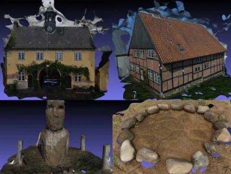
It was stated that the geometrical differences are not very large between image- and distance-based systems. However, it could also be concluded that the image-based systems had problems with large objects such as buildings to obtain geometrically correct results. Visual attractive 3D models could be obtained with the Autodesk Web service, if the objects are not very large and show rotund forms. The scaling of these generated 3D models is carried out using a scale bar, which is placed into the object space during the data recording, or by means of control points. Fig. 3 shows textured surface models, which were automatically generated with the web service Photofly/123D Catch Beta.
Figure 3. Textured 3D surface models – facade of the gatehouse in Jersbek (top left), part of the oldest town house in Bad Segeberg (top right), Moai Vaihu (bottom left) and a turtle
as a petroglyph on Easter Island (bottom right)
4. AUTOMATIC TEXTURE MAPPING OF 3D MODELS
For automatic texture mapping of different large 3D models for applications in architecture and archaeology the software tmapper has been developed in the programming language C++. Basis of this software development are the following three methods, which were suggested by Abdelhafiz (2009) in his PhD thesis about the automatic texture mapping:
1. The Point Cloud Painter (PCP) for the detection of ambient occlusion by comparison of the colours in corresponding image regions,
2. the Multi Layer 3D Image (ML3DImage) algorithm for the automatic texture mapping and
3. the Photo Occlusion Finder (POF) as combination of the two above-mentioned methods.
To apply the algorithms specified above the following conditions must be fulfilled:
- The 3D model must be available as a triangle irregular network (TIN).
- The interior and exterior orientation of the related images must be known with sufficient accuracy.
- The 3D model and the orientation of the related images must refer to the same coordinate system.
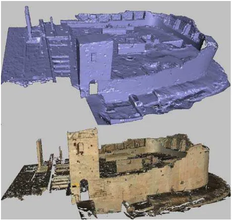
Fig. 4 shows the meshed 3D surface model of the Almaqah temple in Sirwah (Republic of Yemen). The temple was scanned in February 2007 with the terrestrial laser scanner Trimble GS100 and the digital SLR camera Fujifilm Fine Pix S2 pro (Nikkor 28mm lens), modelled with Geomagic (Lindstaedt et al. 2008) and textured automatically afterwards by the Multi Layer 3D Image (ML3DImage) algorithm from Abdelhafiz (2009).
Figure 4. Meshed 3D model of the Almaqah temple in Sirwah/Yemen (left) – automatically textured 3D model (right)
(Abdelhafiz 2009)
Texture mapping is based on a TIN of the respective object, which is generated either as a surface mesh (3D triangulation) or as a 3D CAD construction (surface or volume model). For data recording of 3D objects primarily terrestrial laser scanning, structure light systems resp. fringe projection systems (for smaller objects) and/or photogrammetric procedures are used. These methods can be used separately or in combination. In rare cases a total stations are used for 3D data acquisition for larger and simple objects. For the meshing of surfaces triangulation of 3D point clouds is used, which are derived from measurements of a laser scanner or from dense image matching in imagery (see also Kersten et al. 2012) (see Fig. 5a left). Nevertheless, objects can also be constructed as CAD from 3D point clouds or from discrete photogrammetric point measurements in stereo pairs or in multiple images (Kersten 2006). From the constructed CAD model a triangle network can be derived by converting the AutoCAD file format DWG into another specific format using e.g. the software 3ds Max. The resulting triangle network consists of triangles with various size, which can also be partially covered (Fig. 5a).
Input data for the program tmapper are the digital image data (in JPG format), their orientation parameters and the TIN of the object. The orientation parameters are usually determined in a bundle adjustment with self-calibration. The photogrammetric camera models of the bundle block adjustment programs Pictran B (Technet GmbH) and PHIDIAS (PHOCAD GmbH) are implemented in the program tmapper. The results of these programs can be directly imported.
Figure 5. a) Triangle network derived from a CAD model (left); b) comparison of affine rectification (top) and projective
(correct) rectification (bottom) of synthetic data; c) determination of self-occlusion by ray tracing (centre) and
corresponding original photograph (right)
The ML3DImage algorithm, which has been implemented in the program tmapper, processes the texture mapping in two steps. In the first step the hidden surfaces of object parts and/or of triangles are determined. This process is known in 3D computer graphics as hidden surface determination. Therefor the corner points (knots) of the TIN are projected into the image using the collinearity equations and the known image orientation. Theses rays are defined in space, while the triangle surfaces define planes in object space. The intersection of the rays with a plane is computed. If the intersection point is inside a triangle and closer to the projection centre than the examined corner point is covered by the object and is not visible in the image. Otherwise the point is visible.
In the second step the texture will be selected depending on the visibility of the corner points of each individual triangle. A texture is assigned to a triangle only if their three corner points are visible in at least one image. However, if the three corner points are visible in several images, the image is used, which covers the largest area of the triangle, i.e. the image with the highest resolution is used. The texture is directly taken from the image, i.e. no rigorous rectification (projective transformation) will be carried out with the ML3DImage algorithm. Only an affine transformation is applied. If the triangle surfaces (meshes) are relatively small, the occurred distortions can be neglected. Fig. 5b (top and bottom) demonstrates this effect to the texture of a simulated model of a pyramid. The chess board pattern on the pyramid sides is slightly shifted in the left image, while the pattern in the right image coincides correctly. International Archives of the Photogrammetry, Remote Sensing and Spatial Information Sciences, Volume XXXIX-B5, 2012
The computation of the self-occlusion needs most computing time (>99% of the entire calculation time). In order to accelerate this process, the graphics processing unit (GPU) is to be used in the future. The necessary geometrical operations are directly implemented in the GPU hardware. OpenGL (http://www.opengl.org) or Direct3D could to be used as programming interface. For the visibility analysis the Z-buffer-procedure or ray tracing is often used. The Z-buffer-Z-buffer-procedure is already implemented in the GPU. The GPU has many and fast parallel working geometry computing units (geometry shaders) to run this application.
Ray tracing is an alternative procedure, which is used in the rendering process to produce higher image quality and physical correctness. Since ray tracing can be quite simply implemented, first tests were already performed in tmapper. The result of the visibility analysis by means of Z-buffer-procedures or ray tracing is an image with the same size and orientation of the original photo (see Fig. 5c right). Each pixel indicates whether and which triangle is visible in this photograph. For storing and the visual control the visibility image was converted into a RGB colour image, whereby exactly one RGB colour corresponds to an individual triangle.
5. RESULTS FROM AUTOMATIC TEXTURE MAPPING
The Multi Layer 3D Image (ML3DImage) algorithm, which is implemented in tmapper, has been tested on the basis of the following different data sets (3D models), whose technical specifications are summarised in Table 1.
3D model # points # faces # images camera
Sabaean inscription stone, Sirwah (Yemen)
26,840 53,120 12 Fujifilm S2
Fortress Kristiansten, Trondheim (Norway)
1,399,644 2,797,243 24 Nikon D70
Table 1. Technical specifications of the used test data sets (3D models)
The 3D model of the Sabaean inscription stone of the Almaqah temple in Sirwah (Republic of Yemen), the Kristiansten fortress in Trondheim (Norway) and the town house (Bürgerhaus) in Bad Segeberg (Germany) was derived from terrestrial laser scanning data by triangle meshing in Geomagic. The inscription stone was recorded in February 2007 with the terrestrial laser scanner Trimble GS100 and the digital SLR camera Fujifilm Fine Pix S2 pro (28mm lens) (Kersten 2007), while the fortress building in Trondheim was acquired in September 2010 with the laser scanner Riegl VZ-400 and the digital camera Nikon D70 (28mm lens).
The 3D CAD model of the Fleetschlösschen, located in the district HafenCity of Hamburg, has been generated by combined processing and modelling of laser scanning data (Trimble GS100) and photogrammetric photographs (camera Fujifilm S2 with 28 mm lens) within a framework of a student project in the summer 2006. Fig. 6 shows the twelve photos of the inscription stone used for automatic texture mapping, while in Fig. 7 the textured 3D model is represented, in which still a gap is visible due to a missing photo.
Figure 6. Overview of the photographs used for automatic texture mapping of the Sabaean inscription stone at the
Almaqah temple in Sirwah (Yemen)
Figure 7. Result of automatic texture mapping for the 3D model of the Sabaean inscription stone at the Almaqah temple
in Sirwah (Yemen)
The determination of the image orientation and of the camera calibration parameter was accomplished with the photogrammetric processing software Pictran (Kristiansten fortress, town house and Fleetschlösschen) and with PHIDIAS (inscription stone). Since the additional parameters of self-calibration are included in the adjustment to determine the geometrical camera model, a high geometrical accuracy of the orientation parameters can be obtained in the bundle block adjustment. If signalised control points are visible in the textured model, the accuracy of automatic texture mapping can be examined by superimposition of control points in the textured model. The texture of the control points, represented as transparent spheres, must be exactly coincidence with the position of the control point, represented as transparent spheres (see Fig. 8).
Figure 8. Superimposition of control points in the textured 3D model for geometrical quality control
A problematic aspect is pointed out in Fig. 9: At edge areas of the model colour gradients can occur due to the contrast of the background (e.g. blue sky), which currently cannot be automatically corrected with tmapper. In this case the user would have to perform manual corrections to improve the radiometric quality of the model.
Figure 9. Problem case – colour gradients in the 3D model of the inscription stone
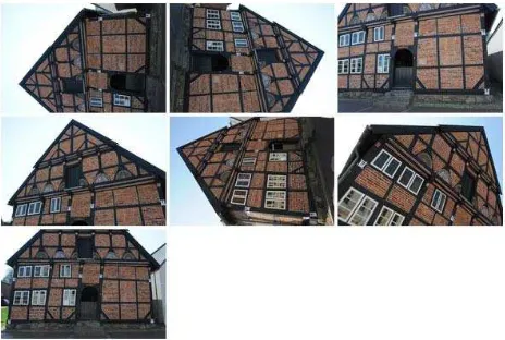
Fig. 10 shows 7 photographs used for automatic texture mapping of the building facade of the town house in Bad Segeberg, while in Fig. 11 two perspective views of the 3D model without and with texture are shown. Fig. 12 illustrates the small TIN from laser scanning without and with texture.
Figure 10. Overview of 7 photographs used for automatic texture mapping of the 3D facade of the town house
(Bürgerhaus) in Bad Segeberg
Figure 11. 3D model of the town house in Bad Segeberg, without texture (left) and with texture (right)
Figure 12. Detail view of the 3D model of the town house, without texture (left) and with texture (right)
Fig. 14 shows 24 photographs used for automatic texture mapping of the fortress building in Trondheim (Norway), while in Fig. 15 two perspective views of the textured 3D model are shown.
Figure 14. Overview of 24 photographs used for automatic texture mapping of the 3D building model of fortress
Kristiansten in Trondheim
Figure 15. Perspective views of the automatically textured 3D building model of fortress Kristiansten
In Fig. 15 the following problems of automatic texture mapping are visible: a) the textures of the building are radiometrically not adjusted (see also Fig. 11 right), since this application is not yet implemented in tmapper, b) some triangles have no texture International Archives of the Photogrammetry, Remote Sensing and Spatial Information Sciences, Volume XXXIX-B5, 2012
(see also Fig. 16), c) roof areas cannot be textured, if no image data are available due to the image acquisition configuration, and d) objects in the foreground are textured on the modelled object without visibility analysis of the foreign covering (see Fig. 14 left, right building side below), if they are not retouched manually before texturing as illustrated in Fig. 2.
Figure 16. Problem case – triangles without texture on the 3D model of fortress Kristiansten
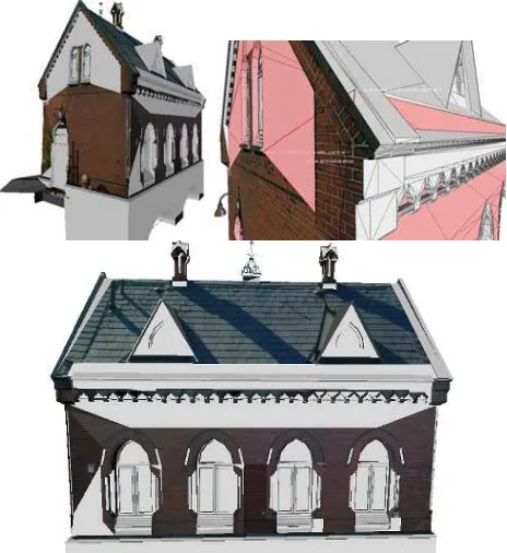
Triangles without texture represent a general problem of the ML3DImage algorithm, because with this method only a texture is assigned to a triangle, if at least all three corner points are visible. Since triangles from laser scanning data are generally relatively small and form a continuous triangle network, most triangles are textured (see Fig. 15). However, as visible in Fig. 16 some triangles at the building of the fortress Kristiansten were not automatically textured, because they are partially covered in all images. Since the 3D models derived from CAD construction can include quite large triangles, the problem of incomplete texture mapping is clearly obvious as shown in Fig. 17 for the Fleetschlösschen after automatic texture mapping. Many triangles were not textured, since self-covering was proven in the visibility analysis, and a large part of the triangle surface is still visible. In the future a visibility analysis will be able to solve the problem by means of Z-buffer-procedures or ray tracing, which is not yet implemented in tmapper.
Figure 17. Result of automatic texture mapping of the 3D CAD model of the Fleetschlösschen in Hamburg-HafenCity –
Problem: triangles without textures
6. CONCLUSION AND OUTLOOK
In this contribution the potential of manual and automatic texture mapping for 3D models is presented on the basis of different examples. Today already fully automatic textured 3D surface models can be generated by pixel-based matching procedures in digital image data, which can achieve the quality of laser scanning data for smaller or medium size objects (Kersten et al. 2012). With the program tmapper a software is developed for the automatic texture mapping of 3D models (triangle meshing and CAD), which uses the Multi Layer 3D Image (ML3DImage) algorithm. However, the restriction showed up that the texture mapping with the ML3DImage method is only useful for a TIN from laser scanning data with small triangles. The method is unsuitable for 3D models from CAD applications due to the determination of the self-covering, which is based only on the corner points of the triangles. Thus, a large number of triangles still remain without texture. A solution for this problem would be the determination of self-covering for each pixel in image space by the Z-buffer-method or ray tracing. Since both procedures need very intensively computation time, all calculations should be carrying out on the graphics processor unit. In order to additionally solve the problem of the foreign covering with the pixel-based visibility analysis, it is obvious to combine the two methods with the Point Cloud Painter algorithm (PCP).
However, currently only manual texture mapping of 3D models can fulfil the high geometrical, radiometric and visual requirements for applications in architecture and archaeology at the moment.
7. REFERENCES
Abdelhafiz, A., 2009: Integrating Digital Photogrammetry and Terrestrial Laser Scanning. DGK Reihe C, Heft Nr. 631. Kersten, Th., 2006. Combination and Comparison of Digital Photogrammetry and Terrestrial Laser Scanning for the Generation of Virtual Models in Cultural Heritage Applications. The 7th International Symposium on Virtual Reality, Archaeology and Cultural Heritage, VAST (2006), M. Ioannides, D. Arnold, F. Niccolucci, K. Mania (Editors), Hilton Nicosia, Cyprus, Oct. 30 - Nov. 4, 2006, pp. 207-214.
Kersten, Th., 2007. Virtual Reality Model of the Northern Sluice of the Ancient Dam in Marib/Yemen by Combination of Digital Photogrammetry and Terrestrial Laser Scanning for Archaeological Applications. International Journal of Architectural Computing, Special Focus on Cultural Heritage, Issue 02, Volume 05, Published by Multiscience, pp. 339-354.
Kersten, Th., Lindstaedt, M., Mechelke, K., Zobel, K., 2012. Automatische 3D-Objektrekonstruktion aus unstrukturierten digitalen Bilddaten für Anwendungen in Architektur, Denkmalpflege und Archäologie. Publikationen der Deutschen Gesellschaft für Photogrammetrie, Fernerkundung und Geoinformation e.V., Band 21, Hrsg. E. Seyfert, 32. Wissenschaftlich-Technische Jahrestagung der DGPF, 14.-17. März 2012 in Potsdam, Proceedings on CD-ROM, pp. 137-148.
Luhmann, T., Robson, S., Kyle, S., Harley, I., 2007. Close Range Photogrammetry: Principles, Techniques and Applications. John Wiley & Sons, 528 pages.