G E T C O N N E C T E D .
W I R E L E S S L Y.
G E T C O N N E C T E D .
W I R E L E S S L Y.
• Select and configure hardware and software for
• Secure your network using WPA encryption or a
• Discover open networks and maintain your privacy
• Use VoIP over a wireless connection to talk on the
• Evaluate wireless data services based on cost, speed,
• Extend your network to give your neighbors free
A B O U T T H E A U T H O R
Motorola and AT&T. He is the author of more than two
PRAISE FOR THE FIRST EDITION,
THE BOOK OF WI-FI
“A plain-English guide for consumers, a bridge over troubled waters for those who want to go wireless but don’t know where to start, what to buy or how to make it all work.”
—SACRAMENTOBEE
“Although there are many good Wi-Fi tutorials available in the market these days . . . The Book of Wi-Fi definitely belongs to the top notch. The author’s practical and fluff-free style liberates this book from the hype and dogmatic tone that prevail in other books.”
—IBMDEVELOPERWORKS
“Highly readable.”
—LINUXUSERANDDEVELOPER
“An outstanding book which gives you a good working knowledge of every aspect of wireless networking and how to set up a small home network or a larger corporate Wi-Fi network with a firewall and VPN.”
—FLASHMX.COM
“Covers the issues without belaboring the details.” —DESKTOPENGINEER.COM
“The author has done an absolutely fabulous job of taking complex information and explaining it in laymen’s terms.”
—BITYARD.COM
“Shines a big bright spotlight on the murky world of Wi-Fi.” —DINGBATMAGAZINE
“Provides a useful foundation for anyone wishing to set up, use, and secure an 802.11b network.”
T H E B O O K
o f
W I R E L E S S
2 N D E D I T I O N
A
P A I N L E S S
G U I D E T O
W I - F I
A N D
B R O A D B A N D W I R E L E S S
by John Ross
THE BOOK OF WIRELESS, 2ND EDITION. Copyright © 2008 by John Ross.
All rights reserved. No part of this work may be reproduced or transmitted in any form or by any means, electronic or mechanical, including photocopying, recording, or by any information storage or retrieval system, without the prior written permission of the copyright owner and the publisher.
12 11 10 09 08 1 2 3 4 5 6 7 8 9
ISBN-10: 1-59327-169-7 ISBN-13: 978-1-59327-169-5
Publisher: William Pollock Production Editor: Megan Dunchak Cover and Interior Design: Octopod Studios Developmental Editor: Tyler Ortman Technical Reviewer: Mike Kershaw Copyeditor: Jeanne Hansen Compositor: Riley Hoffman Proofreader: Michael Shorb Indexer: Nancy Guenther
For information on book distributors or translations, please contact No Starch Press, Inc. directly:
No Starch Press, Inc.
555 De Haro Street, Suite 250, San Francisco, CA 94107
phone: 415.863.9900; fax: 415.863.9950; [email protected]; www.nostarch.com
Librar y of Congress Cataloging-in-Publication Data
Ross, John,
The book of wireless : a painless guide to Wi-Fi and broadband wireless / John Ross. -- 2nd ed. p. cm.
Rev. ed. of: Book of Wi-Fi. c2003. Includes index.
ISBN-13: 978-1-59327-169-5 ISBN-10: 1-59327-169-7
1. Wireless LANs--Installation. 2. Wireless LANs--Standards. 3. IEEE 802.11 (Standard) I. Ross, John, 1947- Book of Wi-Fi. II. Title.
TK5105.78.R67 2008 004.6'8--dc22
2007048461
No Starch Press and the No Starch Press logo are registered trademarks of No Starch Press, Inc. Other product and company names mentioned herein may be the trademarks of their respective owners. Rather than use a trademark symbol with every occurrence of a trademarked name, we are using the names only in an editorial fashion and to the benefit of the trademark owner, with no intention of infringement of the trademark.
The information in this book is distributed on an “As Is” basis, without warranty. While every precaution has been taken in the preparation of this work, neither the author nor No Starch Press, Inc. shall have any liability to any person or entity with respect to any loss or damage caused or alleged to be caused directly or indirectly by the information contained in it.
You see, wire telegraph is a kind of a very, very long cat. You pull his tail in New York and his head is meowing in Los Angeles. Do you understand this? And radio operates exactly the same way: you send signals here, they receive them there. The only difference is there is no cat.
B R I E F C O N T E N T S
Acknowledgments ... xvii
Introduction ...xix
Chapter 1: Introduction to Networking ...1
Chapter 2: Introduction to Wireless Networks ...11
Chapter 3: How Wi-Fi Works ...29
Chapter 4: The Hardware You Need for Wi-Fi ...43
Chapter 5: Managing Your Wi-Fi Connections ...73
Chapter 6: Wi-Fi for Windows ...97
Chapter 7: Wi-Fi for Linux and Unix ...115
Chapter 8: Wi-Fi for Mac ...133
Chapter 9: Installing and Configuring Wi-Fi Access Points ...143
Chapter 10: Long Range Point-to-Point Links ...181
Chapter 11: Connecting to an Existing Wi-Fi Network ...195
Chapter 12: Wireless Network Security ...211
Chapter 13: Alternatives to Wi-Fi: Wireless Broadband Data ...239
Chapter 15: Virtual Private Networks ...265
Chapter 16: Using Broadband for Telephone Calls ...285
Chapter 17: Tips and Troubleshooting ...293
C O N T E N T S I N D E T A I L
A CK N O W LED GM EN T S xvii
I NT RO D UC TI O N xix
1
I NT RO D UC TI O N T O N ET WO R K IN G 1
Moving Data Around ... 2
Bits and Bytes ... 2
Error Checking... 3
Handshaking ... 3
Finding the Destination ... 4
The ISO OSI Model ... 7
The Physical Layer ... 7
The Data Link Layer ... 8
The Network Layer ... 8
The Transport Layer ... 8
The Session Layer... 9
The Presentation Layer ... 9
The Application Layer ... 9
Summary... 9
2 I NT RO D UC TI O N T O W I REL ES S N ET WO R K S 11 How Wireless Networks Work ... 12
Radio ... 13
Wireless Data Networks ... 15
Benefits of Wireless ... 19
Wireless Data Services ... 20
Wi-Fi ... 20
Cellular Mobile Wireless Services ... 23
WiMAX ... 25
What About Bluetooth? ... 26
Frequency Allocations... 26
Choosing a Service ... 27
3 HO W WI - FI W O R KS 29 Wi-Fi Network Controls ... 29
The Physical Layer ... 30
The MAC Layer... 31
Wi-Fi Network Protocols... 32
Public and Private Networks ... 40
Putting It All Together ... 41
4 TH E H A RD WA RE Y O U N EED F O R WI - FI 43 Everybody Speaks the Same Language (More or Less) ... 44
Network Adapters... 45
Form Factor ... 46
Internal vs. External Antennas ... 50
Interoperability... 51
Finding Drivers for Your Adapter... 52
Ease of Use ... 54
Securing Your Network... 56
Documentation and Technical Support ... 56
Reputation ... 57
Adapters for Ad Hoc Networks ... 58
Dual-Purpose Adapters... 58
Access Points ... 59
Operating Standards ... 60
Pure Wireless LANs ... 60
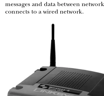
Wireless Access to a Wired LAN ... 61
Combining the Access Point with a Wired Hub ... 62
Broadband Gateways... 63
Multiple Access Points... 63
Enhanced-Performance Access Points ... 65
External Antennas ... 65
Antenna Characteristics ... 67
How to Choose an Antenna ... 68
Rolling Your Own... 69
Where to Use a Directional Antenna ... 69
Antennas Are a Whole Other World ... 71
It’s Time to Buy... 71
5 M A N AGI N G Y O UR W I- F I CO NN EC TI O N S 73 Installing PC Card Adapters ... 74
Installing USB Adapters... 74
Installing an Internal Adapter in a Laptop Computer ... 75
Loading the Driver Software ... 76
Choosing a Control Program ... 77
The Microsoft Wireless Network Connection Utility... 78
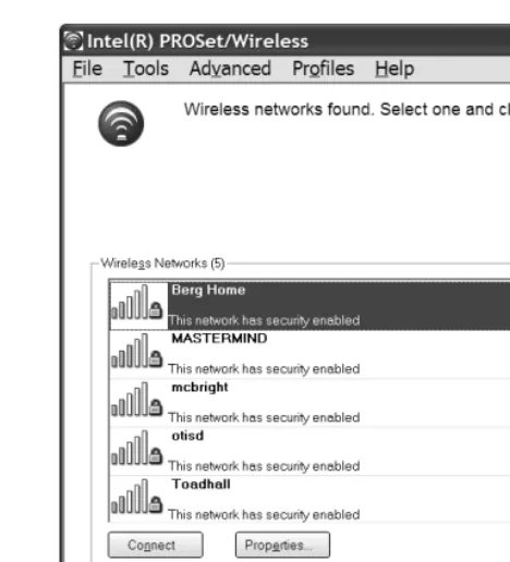
The Intel PROSet/Wireless Program... 86
Other Wi-Fi Adapters and Control Programs ... 88
Status Information... 90
Changing Your Adapter’s Configuration Settings ... 91
Configuring a Network Connection ... 92
The Mobile Life: Moving from One Network to Another ... 92
Beyond Windows... 93
Signal Strength vs. Signal Quality ... 94
6 W I- FI FO R W I N DO W S 97 Windows Network Configuration in General... 99
IP Addresses ... 99
The Subnet Mask... 101
Gateways ... 101
Domain Name Servers... 101
File and Printer Sharing... 102
Network Interface Adapter Options ... 102
Naming Your Computer ... 102
Configuring Windows ... 104
Do You Have the Latest Firmware? ... 104
Using the Windows Wireless Tools... 105
Network Interface Adapter Options ... 110
Naming Your Computer ... 111
Troubleshooting the Connection ... 113
7 W I- FI FO R L I N UX AN D U N IX 115 Drivers, Back Seat and Otherwise ... 116
Where to Find Drivers... 118
Linux Drivers ... 118
Unix Drivers... 120
Wi-Fi Control Programs... 121
Using Built-in Software ... 121
Add-on Wi-Fi Programs... 123
Looking Under the Hood ... 125
Wireless Tools ... 126
Programs Based on the Wireless Tools... 127
Status Display Programs ... 127
Configuring an Access Point ... 128
Wi-Fi for Unix ... 129
Configuration Tools ... 129
8
W I- FI FO R M A C 133
AirPort Components... 134
Setting Up an AirPort Network ... 135
Installing the Hardware... 135
Running the AirPort Setup Assistant... 136
The AirPort Utility ... 137
The AirPort Status Icon ... 137
Using an AirPort Network ... 137
Connecting Macintosh Clients to Other Networks... 138
Using Non-Apple Adapters with a Mac... 138
Connecting an AirPort Card to a Non-AirPort Access Point ... 139
Connecting Other Wi-Fi Clients to an AirPort Network ... 140
Network Properties... 140
Configuring an AirPort Extreme from Windows ... 141
Is AirPort the Answer?... 141
9 I NS T AL L IN G A N D C O N F I GUR IN G W I- FI AC C ESS PO IN TS 143 Installing Access Points... 144
Configuring the Access Point Through a Browser... 146
DHCP and Other Distractions... 148
DNS Addresses... 148
Configuration Commands and Settings ... 149
How Many Access Points?... 152
Using Multiple Access Points... 154
Performing a Site Survey ... 156
Make a Site Plan . . ... 156
Testing, Testing . . . ... 160
Interference Problems... 163
Advantages of Mixed Networks ... 165
Access Points Combined with Hubs and Gateway Routers ... 166
Extending the Network... 167
Legal Issues ... 167
Outdoor Antennas and Access Points... 170
Campus Networks... 175
Connecting the Access Points to a LAN and the Internet ... 176
Networking Your Neighborhood... 177
Keeping Your ISP Happy... 178
Network Security: Everybody Is Your Neighbor ... 179
1 0 L O N G R AN G E P O I NT -T O -P O I N T L I N KS 181 Extending the LAN ... 182
Bridge Routers ... 184
Installing a Point-to-Point Link... 185
Choose a Signal Path ... 186
Reaching the Boondocks: Long-Range Links ... 186
Aligning the Antennas ... 187
Obstructions and Relays... 189
Alternatives to Wi-Fi for Point-to-Point ... 190
Antennas for Network Adapters ... 191
Build Your Own Antenna?... 191
1 1 C O NN EC TI N G TO AN EX IS TI N G WI - FI N ET WO R K 195 Public Wi-Fi Is Not Secure ... 196
Finding a Wi-Fi Hot Spot... 197
Keeping Your Data Secure ... 199
NetStumbler and Other Sniffer Tools... 200
Public Hot Spots ... 202
Municipal Wi-Fi Networks ... 204
“Free Public WiFi”... 205
Unprotected Private Access Points ... 208
1 2 W IR EL ESS N ETW O RK S EC U RI TY 211 Protecting Your Network and Your Data... 214
Protecting Your Computer... 216
Wi-Fi Security Tools ... 217
Network Name (SSID) ... 217
WEP Encryption ... 219
WPA Encryption ... 222
Access Control (MAC Authentication) ... 224
Virtual Private Networks ... 225
Authentication: The 802.1x Standard ... 225
Firewalls ... 226
Keep Wireless Intruders at Bay ... 227
Isolate Your Network from the Internet ... 228
Access Points with Firewalls... 229
Firewall Software ... 231
Turn Off DHCP... 232
Turn Off the Power ... 233
Physical Security ... 233
Sharing Your Network with the World ... 235
Some Final Thoughts About Wi-Fi Security... 237
1 3 A LT ERN A TI V ES TO W I- F I: W IR EL ESS BR O AD BA N D DA TA 239 What’s Wrong with Wi-Fi?... 240
Comparing Technologies ... 242
Choosing a Service Provider... 244
Coverage... 245
Data Speed ... 246
Cost ... 246
Choosing a Network Adapter... 247
Service and Support ... 247
Broadband Wireless Services Around the World ... 248
Connecting to a Wireless Broadband Network ... 248
Using More Than One Computer ... 249
Broadband Security... 250
Clearwire, Sprint, and Other Pre-WiMAX Services ... 250
Broadband Wireless in Automobiles and Other Vehicles... 251
TracNet ... 253
External Antennas ... 254
Safety Issues ... 254
1 4 S M AR TP H O N ES A ND P D AS 255 Connecting to the Internet Through PDAs and Other Handheld Devices... 256
Choosing a Smartphone ... 257
Smartphone Operating Systems ... 258
Which Is Best? ... 263
1 5 V IR TU AL PR I VA TE N ETW O R KS 265 VPN Methods ... 268
VPN Servers ... 268
Configuring a Windows Server for a Wireless VPN ... 269
VPN Servers for Unix ... 270
Network Hardware with Built-in VPN Support ... 271
VPN Client Software... 272
Configuring Windows for VPN ... 272
The Microsoft L2TP/IPsec VPN Client ... 276
Making the Connection in Windows... 276
Windows XP Options ... 277
VPN Clients for Unix... 279
Using a Wireless VPN ... 280
Making the Connection... 282
Bypassing the VPN ... 283
1 6
US I N G B RO A D BA ND F O R T ELEP H O N E C A LL S 285
VoIP over Broadband Wireless and WiMAX ... 287
Voice over Wi-Fi ... 289
1 7 TI P S A ND T RO U BL E S HO O TI N G 293 My computer doesn’t detect my network adapter. ... 293
The wireless control program tries to run, even if I’m not using my adapter. ... 295
My computer won’t associate with the local network. ... 296
My computer connects to the wrong network. ... 296
I can see the local network, but I can’t connect to the Internet. ... 297
I can see the Internet, but I can’t see other computers on my LAN. ... 297
The signal strength is weak or signal quality is low. ... 297
I can’t find a public network. ... 298
I don’t know if I’m within range of a network. ... 298
The network is slow. ... 298
My computer drops its connection. ... 299
My Wi-Fi network has crashed. ... 299
Can I improve performance with an external antenna? ... 300
What else can I do to improve performance? ... 300
When I move to a different access point, the adapter loses the connection. ... 301
Where can I find a copy of the Wi-Fi standards? ... 301
How can I find out who made my network adapter?... 301
Is the software that came with my network adapter or access point up to date? ... 302
I’m having trouble connecting to a broadband network. ... 303
I’m having trouble connecting to my VPN. ... 303
How can I extend the life of my computer’s battery? ... 304
Can I use my access point as a network bridge? ... 304
I’ve heard that radio signals from cellular phones might be dangerous. What about Wi-Fi? ... 305
A C K N O W L E D G M E N T S
I’m grateful to everybody at No Starch Press for their help and advice as this book moved from idea to print. In particular, Tyler Ortman, Megan Dunchak, Michael Kershaw, and Riley Hoffman have made this a much better book than it would have been without their attention. Any remaining faults in the book are, of course, my responsibility.
I N T R O D U C T I O N
This is a book for people who want to use
the Internet everywhere—not just in the
office or in the room at home where there’s a
telephone or cable connection, but in the backyard,
at the public library, at a highway rest area, or in a hotel
lobby. In this book you will learn how to choose the
best wireless data service for your particular needs, how to set up your com-puter for wireless, and how to design and install your own wireless network. We’ll also describe some wireless products and services that you might not have known about, such as the ability to make low-cost, worldwide Voice over Internet (VoIP) telephone calls from your laptop computer.
Internet services can change the way we live, work, and entertain ourselves. When wireless broadband Internet services work properly, they’re practically invisible; just turn on the computer or a smaller portable device such as a smartphone, and a universe of information is immediately at your fingertips. But we’re talking about computers, so complications are always possible. In order to help you identify the causes and solutions for wireless connection problems, the first few chapters of this book offer details about how wireless data communication systems work, including the surprising tale of the avant-garde composer and the glamorous actress whose wartime invention provided the foundation of modern spread-spectrum technology.
As you read this book, I hope you will remember that a wireless network, and for that matter, any kind of communications technology, is a means to an end that you use to achieve some other objective. Remember that your original goal was to find out if your favorite team won, invite your friends to a dinner party, read your class notes, or watch the latest YouTube videos. If you have to concentrate on making your wireless connection, you’re doing some-thing wrong.
You’re in control. The computer and the network should do things the way you want to do them, rather than forcing you to adjust your life or work to meet the machine’s requirements. If you have trouble making your wire-less connection (or any other computer activity) work “properly,” it’s almost always the computer’s fault, or the fault of the people who designed the hardware and software. The computer and the network are your servants, and not the other way around.
New wireless network products and services are appearing all the time, so the information in this book represents a snapshot of a moving target. Within another year or two, manufacturers will have replaced some of the products described here with new and better models, and the wireless service providers will offer faster connections over wider areas. The specific makes and models will change, but the general principles ought to remain.
The first three chapters of this book explain how data networks operate, how wireless technology can extend data networks beyond the reach of wired connections, and how Wi-Fi networks work. Next, Chapter 4 describes the hardware needed for Wi-Fi and how to design and install your own Wi-Fi network. Chapters 5 and 6 provide the information you need to use a Wi-Fi network to connect to the Internet from a computer running Microsoft Windows. Chapter 7 covers Wi-Fi clients for the Linux and Unix operating systems, and Chapter 8 provides similar information for Macintosh OS X. Chapter 9 explains how to install and configure Wi-Fi access points, and Chapter 10 covers long-range, point-to-point Wi-Fi links. Chapters 11 and 12 cover connecting to existing Wi-Fi networks and Wi-Fi security.
In Chapter 13, we’ll move away from Wi-Fi and describe some alter-native broadband wireless services, including EV-DO, EDGE, and WiMAX. Chapter 14 explains how to use Wi-Fi and broadband services with smart-phones and other pocket-size computers, Chapter 15 describes virtual private networks (VPNs), and Chapter 16 explains how to use wireless links to place telephone calls through the Internet. Finally, Chapter 17 offers trouble-shooting tips and general advice.
Most readers won’t read this book from cover to cover, but you’ll probably find something you can use in every chapter. In particular, please don’t ignore the chapters on security and VPNs—they contain essential information that can keep your network and your data safe. If all your computers use Windows, you can skip the Linux/Unix and Macintosh chapters.
1
I N T R O D U C T I O N T O
N E T W O R K I N G
Broadband wireless networks are one
more step toward the Internet’s ultimate
destiny of interconnecting everything in the
known universe.
A wireless network combines two kinds of communication technology: data networks that make it possible to share information among two or more computers, and radio (or wireless) communication that uses electromagnetic radiation to move information from one place to another.
The next chapter explains how these three broadband wireless networks work. But before we go into detail about specific wireless data network services, it will be helpful to understand networks in more general terms.
Moving Data Around
To begin, let’s review the general structure of computer data and the methods that networks use to move data from one place to another. This is very basic stuff that might already be familiar to you, but bear with me for a few pages. This really will help you to understand how a wireless network operates.
Bits and Bytes
As you probably know, the processing unit of a computer can recognize only two information states: either a signal is present or not present at the input to the processor. These two conditions are usually described as 1 and 0, on and off, or mark and space. Each instance of a 1 or a 0 is a bit.
The form that each 1 or 0 takes varies in different types of communication channels. It can be a light, a sound, or an electrical charge that is either on or off, a series of long and short sounds or light flashes, two different audio tones, or two different radio frequencies.
Individual bits are not particularly useful, but when you string 8 of them together into a byte, you can have 256 different combinations. That’s enough to assign different sequences to all the letters in the alphabet (both upper- and lowercase), the 10 digits from 0 to 9, spaces between words, and other symbols such as punctuation marks and letters used in foreign alphabets. A modern computer recognizes and processes several 8-bit bytes at the same time. When processing is complete, the computer transmits the same stream of bits at its output. The output might be connected to a printer, a video display, or a data communication channel. Or it might be something else entirely, such as a series of flashing lights. Figure 1-1 is an example of a sequence of bits.
Figure 1-1: These bits form the sequence of A (01000001) and n (01101110).
The inputs and outputs that we’re concerned about here are the ones that form a communication circuit. Like the computer processor, a data channel can recognize only one bit at a time. Either there’s a signal on the line or there isn’t.
However, over short distances, it’s possible to send the data through a cable that carries eight (or some multiple of eight) signals in parallel through eight separate wires. Obviously, a parallel connection can be eight times faster than sending one bit through a single wire, but those eight wires cost eight times as much as a single wire. That added cost is insignificant when the wires are only a foot or two long, but when you’re trying to send the data over a long distance, that additional cost can be prohibitive. And when you’re
using existing circuits, such as telephone lines, you don’t have any choice; you must find a way to send all eight bits through the existing pair of wires (or other media). The solution is to transmit one bit at a time with some additional bits and pauses that identify the beginning of each new byte. This is a serial data communication channel, which means that you’re sending bits one after another. At this stage, it doesn’t matter what medium you use to transmit those bits—it could be electrical impulses on a wire, two different audio tones, a series of flashing lights, or even a lot of notes attached to the legs of carrier pigeons—but you must have a method for converting the output of the computer to the signals used by the transmission medium and converting it back again at the other end.
Error Checking
In a perfect transmission circuit, the signal that goes in at one end will be absolutely identical to the one that comes out at the other end. But in the real world, there’s almost always some kind of noise that can interfere with our original pure signal. Noise is defined as anything that is added to the original signal; it could be caused by a lightning strike, interference from another communication channel, or dirt on an electrical contact someplace in the circuit (or in the case of those carrier pigeons, an attack by a marauding hawk). Whatever the source, noise in the channel can interrupt the flow of data. In a modern communication system, those bits are pouring through the circuit extremely quickly—millions of them every second—so a noise hit for even a fraction of a second can obliterate enough bits to turn your data into digital gibberish.
Therefore, you must include a process called error checking in your data stream. Error checking is accomplished by adding some kind of standard information to each byte. In a simple computer data network, the hand-shaking information (described in the next section) is called the parity bit, which tells the device receiving each byte whether the sum of the ones and zeroes inside the byte is odd or even. If the receiving device discovers that the parity bit is not what it expected, it instructs the transmitter to send the same byte again. This value is called a checksum. More complex networks, including wireless systems, include additional error checking handshaking data with each string of data.
Handshaking
Of course, the computer that originates a message or a stream of data can’t just jump online and start sending bytes. First it has to warn the device at the other end that it is ready to send data and make sure that the intended recipient is ready to accept data. To accomplish this, a series of handshaking requests and answers must surround the actual data.
The sequence of requests goes something like this:
Origin: “Hey destination! I have some data for you.”
Origin: “Here comes the data.”
Origin: Data data data data . . . checksum
Origin: “That’s the message. Did you get it?”
Destination: “I got something, but it appears to be damaged.”
Origin: “Here it is again.”
Origin: Data data data data . . . checksum
Origin: “Did you get it that time?”
Destination: “Yup, I got it. I’m ready for more data.”
We can leave the specific contents of the handshaking information to the network designers and engineers, but it’s important to understand that every bit that moves through a computer data network is not part of the original information that arrived at the input computer. In a complex network, such as a wireless data channel, as much as 40 percent or more of the transmitted data is handshaking and other overhead. It’s all essential, but every one of those bits increases the amount of time that the message needs to move through the network.
Finding the Destination
Communication over a direct physical connection (e.g., a wired connection) between the origin and destination doesn’t need to include any kind of address or routing information as part of the message. You might have to set up the connection first (by placing a telephone call or plugging cables into a switchboard), but after you’re connected, the link remains in place until you instruct the system to disconnect. This kind of connection is great for voice and simple data links, but it’s not efficient for digital data on a complex net-work that serves many origins and destinations because a single connection ties up the circuit all the time, even when no data is moving through the channel.
The alternative is to send your message to a switching center that will hold it until a link to the destination becomes available. This is known as a store and forward system. If the network has been properly designed for the type of data and the amount of traffic in the system, the waiting time will be insignificant. If the communication network covers a lot of territory, you can forward the message to one or more intermediate switching centers before it reaches its ultimate destination. The great advantage of this approach is that many messages can share the same circuits on an as-available basis.
switching centers. Each data packet must also contain another set of infor-mation: the address of the packet’s destination, the sequence of the packet relative to other packets in the original transmission, and so forth. Some of this information instructs the switching centers where to forward each packet, and other information tells the destination device how to reassemble the data in the packet back into the original message.
That same pattern is repeated every time you add another layer of activity to a communication system. Each layer can attach additional information to the original message and strip off that information after it has done what-ever the added information instructed it to do. By the time a message travels from a laptop computer on a wireless network through a local area network (LAN) and an Internet gateway to a distant computer that is connected to another LAN, a dozen or more information attachments might be added and removed before the recipient reads the original text. A package of data that includes address and control information ahead of the bits that contain the content of the message, followed by an error-checking sequence, is called a frame. Both wired and wireless networks divide the data stream into frames that contain various forms of handshaking information along with the original data.
It might be helpful to think of these bits, bytes, packets, and frames as the digital version of a letter that you send through a complicated mail delivery system:
1. You write a letter and put it into an envelope. The name and address of the recipient is on the outside of the envelope.
2. You take the letter to the mail room, where a clerk puts your envelope into a bigger Express Mail envelope. The big envelope has the name and address of the office where the recipient works.
3. The mail room clerk takes the big envelope to the post office where another clerk puts it into a mail sack. The post office attaches a tag to the sack, marked with the location of the post office that serves the recipient’s office.
4. The mail sack travels on a truck to the airport, where it is loaded into a shipping container along with other sacks going to the same destination city. The shipping container has a label that tells the freight handlers there’s mail inside.
5. The freight handlers place the container inside an airplane.
6. At this point, your letter is inside your envelope, which is inside the Express Mail envelope, which is inside a mail sack, inside a container, inside an airplane. The airplane flies to another airport near the desti-nation city.
8. The freight handlers remove the sack from the shipping container and put it on another truck.
9. The truck takes the sack to a post office near the recipient’s office. 10. At the post office, another mail clerk takes the big envelope out of the
sack and gives it to a letter carrier.
11. The letter carrier delivers the big Express Mail envelope to the recipient’s office.
12. The receptionist in the office takes your envelope out of the Express Mail envelope and gives it to the recipient.
13. The recipient opens your envelope and reads the letter.
At each step, the information on the outside of the package tells some-body how to handle it, but that person doesn’t care what’s inside. Neither you nor the person who ultimately reads your letter ever sees the big Express Mail envelope, the mail sack, the truck, the container, or the airplane, but every one of those containers plays an important part in moving your letter from here to there.
Instead of envelopes, sacks, containers, and airplanes, an electronic message uses strings of data at the beginning or end of each packet to tell the system how and where to handle your message, but the end result is just about the same. In the OSI network model (described in the next section), each mode of transportation is a separate layer.
Fortunately, the network software adds and removes all of the preambles, addresses, checksums, and other information automatically so you and the person receiving your message never see them.
The ISO OSI Model
As the package delivery example demonstrates, the information itself is only part of the process. When information moves across a network, it’s essential that all of the parties involved—the originator, the ultimate recipient, and everything in between—agree that they will use the same formatting, timing, and routing rules and specifications. These rules (also called protocols) define the network’s internal “plumbing” and the form of the information that moves through it.
As network communication has become more complex, the community of network designers has accepted the International Organization for Stand-ardization’s (ISO) Open Systems Interconnection (OSI) model to identify the individual elements of a network link. The OSI model applies to just about any kind of data communication system, including the broadband wireless network that will be described in the rest of this book.
Because everybody in the communication industry uses the OSI model, it encourages hardware and software designers to create systems and services that can exchange information with similar products from other manufac-turers. Without the OSI model or something like it, it would not be possible to expect equipment from more than one source to work together.
The OSI model also allows a designer to change just one element of the network without the need to design everything else from scratch. For example, a wireless network uses radio signals instead of cables at the physical layer
The Physical Layer
As the name suggests, the physical layer defines the physical media or hardware that carries signals between the end points of a network connection. The physical layer might be a coaxial cable, a pair of telephone wires, flashing lights, or radio waves.
and adds routing information at the data link layer, but it keeps the existing protocols and specifications for everything else. A complex network (such as the Internet) can use wired connections for one part of the signal path and wireless connections for another.
The OSI model is usually portrayed as a stack of seven layers with each layer acting as a foundation for the layer directly above it as shown in Figure 1-2.
Starting at the bottom, the seven layers of the OSI model are described in the following sections.
The specifications of a network’s physical layer might include the shape of the shell and the pin numbers in a cable connector, the voltages that define the 0 and 1 (on and off) values, the durations of individual data bits, and the radio frequencies and modulation methods used by a radio trans-mitter and receiver.
The Data Link Layer
The data link layer handles transmission of data across the link defined by the physical layer. It specifies the format of each data packet that moves across the network, including the destination of each packet, the physical structure of the network, the sequence of packets (to make sure that the packets arrive in the correct order), and the type of flow control (to make sure that the transmitter doesn’t send data faster than the receiver can handle it). Each packet also includes a checksum that the receiver uses to confirm that the data was not corrupted during transmission, as well as the string of bits and bytes that contains the actual data inside the packet. Therefore, it contains the software that creates and interprets the signals that move through the physical layer.
In both wired and wireless Ethernet, every physical device that is con-nected to the network has a unique 48-bit media access control (MAC) address that identifies it to the network. The header (the first part of the data string inside of a packet) includes the MAC addresses of both the origin and des-tination of that packet.
The Network Layer
The network layer specifies the route that a signal uses to move from the source to the destination independently of the physical media. At the network level, it doesn’t matter whether the data moves through a cable, radio waves, or if it uses some combination of both because that’s all handled at a lower level.
Within the Internet, the exchange of data between LANs, wide area networks (WANs), and the core Internet trunk circuits occurs at the network layer.
The Transport Layer
The Session Layer
The session layer defines the format that the programs connected through the transport layer use to exchange data. If the programs use passwords or other authentication to assure that the program at the distant end of the connection is allowed to use a local program, that authentication happens in the session layer.
The Presentation Layer
The presentation layer controls the way each computer handles text, audio, video, and other data formats. For example, if a distant computer sends a picture in JPEG format, the software that converts the data string to a picture on a monitor or a printer operates at the presentation layer.
The Application Layer
The application layer handles the commands and data that move through the network. For example, when you send an email message, the content of your message (but not the address or the formatting information) is in the applica-tion layer. Most of the words, pictures, sounds, and other forms of informaapplica-tion that you send through a network enter the system through the application layer.
Summary
2
I N T R O D U C T I O N T O W I R E L E S S
N E T W O R K S
Up to a point, it’s quite possible to treat
your wireless network as a set of black boxes
that you can turn on and use without knowing
much about the way they work. That’s the way
most people relate to the technology that surrounds
them. You shouldn’t have to worry about the technical specifications just to place a long-distance telephone call or heat your lunch in a microwave oven or connect your laptop computer to a network. In an ideal world (ha!), the wireless link would work as soon as you turn on the power switch.
But wireless networking today is about where broadcast radio was in the late 1920s. The technology was out there for everybody, but the people who understood what was happening behind that Bakelite-Dilecto panel (Figure 2-1) often got better performance than the ones who just expected to turn on the power switch and listen.
chapter describes the standards and specifications that control wireless networks and explains how data moves through the network from one computer to another.
Figure 2-1: Every new technology goes through the tweak-and-fiddle stage.
When the network is working properly, you should be able to use it with-out thinking abwith-out all of that internal plumbing—just click a few icons and you’re connected. But when you’re designing and building a new network, or when you want to improve the performance of an existing network, it can be essential to understand how all that data is supposed to move from one place to another. And when the network does something you aren’t expecting it to do, you will need a basic knowledge of the technology to do any kind of useful troubleshooting.
How Wireless Networks Work
when you invent a new network. In terms of the OSI reference model, the radio signal operates at the physical layer, and the data format controls several of the higher layers. The network structure includes the wireless network interface adapters and base stations that send and receive the radio signals. In a wireless network, the network interface adapters in each computer and base station convert digital data to radio signals, which they transmit to other devices on the same network, and they receive and convert incoming radio signals from other network elements back to digital data.
Each of the broadband wireless data services use a different combination of radio signals, data formats, and network structure. We’ll describe each type of wireless data network in more detail later in this chapter, but first, it’s valuable to understand some general principles.
Radio
The basic physical laws that make radio possible are known as Maxwell’s equations, identified by James Clerk Maxwell in 1864. Without going into the math, Maxwell’s equations show that a changing magnetic field will produce an electric field, and a changing electric field will produce a magnetic field. When alternating current (AC) moves through a wire or other physical conductor, some of that energy escapes into the surrounding space as an alternating magnetic field. That magnetic field creates an alternating electric field in space, which in turn creates another magnetic field and so forth until the original current is interrupted.
This form of energy in transition between electricity and magnetic energy is called electromagnetic radiation, or radio waves. Radio is defined as the radiation of electromagnetic energy through space. A device that produces radio waves is called a transmitter, and a complementary device that detects radio waves in the air and converts them to some other form of energy is called a receiver. Both transmitters and receivers use specially shaped devices called antennas to focus the radio signal in a particular direction, or pattern, and to increase the amount of effective radiation (from a transmitter) or sensitivity (in a receiver).
By adjusting the rate at which alternating current flows from each trans-mitter through the antenna and out into space (the frequency), and by adjusting a receiver to operate only at that frequency, it’s possible to send and receive many different signals, each at a different frequency, that don’t interfere with one another. The overall range of frequencies is known as the radio spectrum. A smaller segment of the radio spectrum is often called a band.
Radio frequencies and other AC signals are expressed as cycles per second, or hertz (Hz), named for Heinrich Hertz, the first experimenter to send and receive radio waves. One cycle is the distance from the peak of an AC signal to the peak of the next signal. Radio signals generally operate at frequencies in thousands, millions, or billions of hertz (kilohertz or KHz, megahertz or MHz, and gigahertz or GHz, respectively).
individual letters and other characters. The most widely used set of these patterns was Morse code, named for the inventor of the telegraph, Samuel F.B. Morse, where this code was first used.
In order to transmit speech, music, and other sounds via radio, the trans-mitter alters, or modulates, the AC signal (the carrier wave) by either mixing an audio signal with the carrier as shown in Figure 2-2 (this is called amplitude modulation, or AM) or by modulating the frequency within a narrow range as shown in Figure 2-3 (this is called frequency modulation, or FM). The AM or FM receiver includes a complementary circuit that separates the carrier from the modulating signal.
Figure 2-2: In an AM signal, the audio modulates the carrier.
Figure 2-3: In an FM signal, the audio modulates the radio frequency.
Because two or more radio signals using the same frequency can often interfere with one another, government regulators and international agencies, such as the International Telecommunication Union (ITU), have reserved certain frequencies for specific types of modulation, and they issue exclusive licenses to individual users. For example, an FM radio station might be licensed to operate at 92.1 MHz at a certain geographical location. Nobody else is allowed to use that frequency in close enough proximity to interfere with that signal. On the other hand, some radio services don’t require a license. Most unlicensed services are either restricted to very short distances, to specific frequency bands, or both.
Both AM and FM are analog methods because the signal that comes out of the receiver is a replica of the signal that went into the transmitter. When we send computer data through a radio link, it’s digital because the content has been converted from text, computer code, sounds, images or other infor-mation into ones and zeroes before it is transmitted, and it is converted back to its original form after it is received. Digital radio can use any of several different modulation methods: The ones and zeroes can be two different audio tones, two different radio frequencies, timed interruptions to the carrier, or some combination of those and other techniques.
Amplitude
Time
Amplitude
Wireless Data Networks
Each type of wireless data network operates on a specific set of radio fre-quencies. For example, most Wi-Fi networks operate in a special band of radio frequencies around 2.4 GHz that have been reserved in most parts of the world for unlicensed point-to-point spread spectrum radio services. Other Wi-Fi systems use a different unlicensed band around 5 GHz.
Unlicensed Radio Services
Unlicensed means that anybody using equipment that complies with the tech-nical requirements can send and receive radio signals on these frequencies without a radio station license. Unlike most radio services (including other broadband wireless services), which require licenses that grant exclusive use of that frequency to a specific type of service and to one or more specific users, an unlicensed service is a free-for-all where everybody has an equal claim to the same airwaves. In theory, the technology of spread spectrum radio makes it possible for many users to co-exist (up to a point) without significant interference.
Point-to-Point
A point-to-point radio service operates a communication channel that carries information from a transmitter to a single receiver. The opposite of point-to-point is a broadcast service (such as a radio or television station) that sends the same signal to many receivers at the same time.
Spread Spectrum
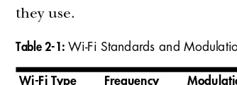
Spread spectrum is a family of methods for transmitting a single radio signal using a relatively wide segment of the radio spectrum. Wireless Ethernet networks use several different spread spectrum radio transmission systems, which are called frequency-hopping spread spectrum (FHSS), direct-sequence spread spectrum (DSSS), and orthogonal frequency division multiplexing (OFDM). Some older data networks use the slower FHSS system, but the first Wi-Fi networks used DSSS, and more recent systems use OFDM. Table 2-1 lists each of the Wi-Fi standards and the type of spread spectrum modulation they use.
Spread spectrum radio offers some important advantages over other types of radio signals that use a single narrow channel. Spread spectrum is extremely efficient, so the radio transmitters can operate with very low power. Because the signals operate on a relatively wide band of frequencies, Table 2-1: Wi-Fi Standards and Modulation Type
Wi-Fi Type Frequency Modulation
802.11a 5 GHz OFDM
802.11b 2.4 GHz DSSS
they are less sensitive to interference from other radio signals and electrical noise, which means they can often get through in environments where a conventional narrow-band signal would be impossible to receive and under-stand. And because a frequency-hopping spread spectrum signal shifts among more than one channel, it can be extremely difficult for an unauthorized listener to intercept and decode the contents of a signal.
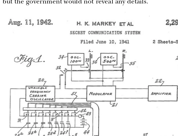
Spread spectrum technology has an interesting history. It was invented by the actress Hedy Lamarr and the American avant-garde composer George Antheil as a “Secret Communication System” for directing radio-controlled torpedoes that would not be vulnerable to enemy jamming. Before she came to Hollywood, Lamarr had been married to an arms merchant in Austria, where she learned about the problems of torpedo guidance at dinner parties with her husband’s customers. Years later, shortly before the United States entered World War II, she came up with the concept of changing radio fre-quencies to cut through interference. The New York Times reported in 1941 that her “red hot” invention (Figure 2-4) was vital to the national defense, but the government would not reveal any details.
Figure 2-4: Hedy Lamarr and George Antheil received this patent in 1942 for the invention that became the foundation of spread spectrum radio communication. She is credited here under her married name, H.K. Markey. The complete docu-ment is accessible at http://uspto.gov.
change radio frequencies in a spread spectrum transmission. The original slotted paper tape system had 88 different radio channels—one for each of the 88 keys on a piano.
In theory, the same method could be used for voice and data communi-cation as well as guiding torpedoes, but in the days of vacuum tubes, paper tape, and mechanical synchronization, the whole process was too complicated to actually build and use. By 1962, solid-state electronics had replaced the vacuum tubes and piano rolls, and the technology was used aboard US Navy ships for secure communication during the Cuban Missile Crisis. Today, spread spectrum radios are used in the US Air Force Space Command’s Milstar Satellite Communications System, in digital cellular telephones, and in wireless data networks.
Frequency-Hopping Spread Spectrum
Lamarr and Antheil’s original design for spread spectrum radio used a frequency-hopping system (FHSS). As the name suggests, FHSS technology divides a radio signal into small segments and “hops” from one frequency to another many times per second as it transmits those segments. The transmitter and the receiver establish a synchronized hopping pattern that sets the sequence in which they will use different subchannels.
FHSS systems overcome interference from other users by using a narrow carrier signal that changes frequency many times per second. Additional transmitter and receiver pairs can use different hopping patterns on the same set of subchannels at the same time. At any point in time, each transmission is probably using a different subchannel, so there’s no interference between signals. When a conflict does occur, the system resends the same packet until the receiver gets a clean copy and sends a confirmation back to the transmitting station.
For some older 802.11 wireless data services, the unlicensed 2.4 MHz band is split into 75 subchannels, each of them 1 MHz wide. Because each frequency hop adds overhead to the data stream, FHSS transmissions are relatively slow.
Direct-Sequence Spread Spectrum
The direct-sequence spread spectrum (DSSS) technology that controls 802.11b networks uses an 11-chip Barker Sequence to spread the radio signal through a single 22 MHz–wide channel without changing frequencies. Each DSSS link uses just one channel without any hopping between frequencies. As Figure 2-5 shows, a DSSS transmission uses more bandwidth, but less power than a conventional signal. The digital signal on the left is a conventional transmission in which the power is concentrated within a tight bandwidth. The DSSS signal on the right uses the same amount of power, but it spreads that power across a wider band of radio frequencies. Obviously, the 22 MHz DSSS channel is a lot wider than the 1 MHz channels used in FHSS systems.
original. Because most interference is likely to occupy a narrower bandwidth than a DSSS signal, and because each bit is divided into several chips, the receiver can usually identify noise and reject it before it decodes the signal.
Figure 2-5: A conventional signal (left) uses a narrow radio frequency bandwidth. A DSSS signal (right) uses a wider bandwidth but a less powerful signal.
Like other networking protocols, a DSSS wireless link exchanges hand-shaking messages within each data packet to confirm that the receiver can understand each packet. For example, the standard data transmission rate in an 802.11b DSSS WI-Fi network is 11Mbps, but when the signal quality won’t support that speed, the transmitter and receiver use a process called dynamic rate shifting to drop the speed down to 5.5Mbps. The speed might drop because a source of electrical noise near the receiver interferes with the signal or because the transmitter and receiver are too far apart to support full-speed operation. If 5.5Mbps is still too fast for the link to handle, it drops again, down to 2Mbps or even 1Mbps.
Orthogonal Frequency Division Multiplexing
Orthogonal frequency division multiplexing (OFDM) modulation, used in 802.11a Wi-Fi networks, is considerably more complicated than DSSS technology. The physical layer splits the data stream among 52 parallel bit streams that each use a different radio frequency called a subcarrier. Four of these sub-carriers carry pilot data that provides reference information about the remaining 48 subcarriers, in order to reduce signal loss due to radio inter-ference or phase shift. Because the data is divided into 48 separate streams that move through separate subcarriers in parallel, the total transmission speed is much greater than the speed of data through a single channel.
The subcarrier frequencies in an OFDM signal overlap with the peak of each subcarrier’s waveform match-ing the baseline of the overlappmatch-ing signals as shown in Figure 2-6. This is called orthogonal frequency division. The 802.11a standard specifies a total of eight data channels that are 20 MHz wide. Each of these channels is divided into 52 300 kHz
subcarriers. Figure 2-6: In OFDM, the peaks of over-lapping frequencies don’t interfere with one another.
Frequency
Signal Strength
2.41 GHz 2.5 GHz
0.1mW
When a Wi-Fi radio receiver detects an 802.11a signal, it assembles the parallel bit streams back into a single high-speed data stream and uses the pilot data to check its accuracy. Under ideal conditions, an 802.11a network can move data at 54Mbps, but like DSSS modulation, the OFDM transmitter and receiver automatically reduce the data speed when the maximum trans-mission rate is not possible due to interference, weak signals, or other less-than-perfect atmospheric conditions.
The more recent 802.11g specification was designed to combine the best features of both 802.11b (greater signal range) and 802.11a (higher speed). To accomplish this objective, it uses OFDM modulation on the 2.4 GHz fre-quency band.
Why This Matters
The great science fiction writer Arthur C. Clarke once observed that “Any sufficiently advanced technology is indistinguishable from magic.” For most of us, the technology that controls high-speed spread spectrum radio could just as easily be a form of magic, because we don’t need to understand the things that happen inside a transmitter and a receiver; they’re just about invisible when we connect a computer to the Internet. As mentioned earlier in this chapter, you don’t need to understand these technical details about how a Wi-Fi transmitter splits your data into tiny pieces and reassembles them into data unless you’re a radio circuit designer.
But when you know that there’s a well-defined set of rules and methods that make the connection work (even if you don’t know all the details), you are in control. You know that it’s not magic, and if you think about it, you might also know some of the right questions to ask when the system doesn’t work correctly. If knowledge is power, then knowledge about the technology you use every day is the power to control that technology rather than just use it.
Benefits of Wireless
Wireless broadband provides Internet access to mobile devices in addition to allowing network operators to extend their networks beyond the range of their wired connections. For our purposes, two-way radio is the most sensible approach to wireless broadband, but other methods (such as infrared light or visible signaling) are also possible. Connecting your computer to the Internet (or a local network) by radio offers several advantages over connect-ing the same computer through a wired connection. First, wireless provides convenient access for portable computers; it’s not necessary to find a cable or network data outlet. And second, it allows a user to make a connection from more than one location and to maintain a connection as the user moves from place to place. For network managers, a wireless connection makes it possible to distribute access to a network without the need to string wires or cut holes through walls.
a communication program. Depending on the type of wireless network you’re using, you might also be able to maintain the same connection in a moving vehicle.
When you’re installing your own network, it’s often easier to use Wi-Fi links to extend your network and your Internet connection to other rooms because a wired system requires a physical path for the cables between the network router or switch and each computer. Unless you can route those cables through a false ceiling or some other existing channel, this almost always means that you must cut holes in your walls for data connectors and feed wires inside the walls and under the floors. A radio signal that passes through those same walls is often a lot neater and easier.
Wireless Data Services
Because radio signals move through the air, you can set up a network connec-tion from any place within range of the network base staconnec-tion’s transmitter; it’s not necessary to use a telephone line, television cable, or some other dedicated wiring to connect your computer to the network. Just turn on the radio connected to the computer and it will find the network signal. There-fore, a radio (or wireless) network connection is often a lot more convenient than a wired one.
This is not to say that wireless is always the best choice. A wired network is usually more secure than a wireless system because it’s a lot more difficult for unauthorized eavesdroppers and other snoops to monitor data as it moves through the network, and a wired link doesn’t require as many complex negotiations between the sender and receiver on protocols and so forth. In an environment where your computer never moves away from your desk and there are no physical obstacles between the computer and the network access point, it’s often easier to install a data cable between the computer and a modem.
So now we have a bunch of radio transmitters and receivers that all operate on the same frequencies and all use the same kind of modulation. (Modulation is the method a radio uses to add some kind of content, such as voice or digital data, to a radio wave.) The next step is to send some network data through those radios. Several different wireless data systems and services are available to connect computers and other devices to local networks and to the Internet, including Wi-Fi, WiMAX, and a handful of services based on the latest generations of cellular mobile telephone technology.
Wi-Fi
802.11b standard provides additional specifications for wireless Ethernet networks. A related document, IEEE 802.11a, describes wireless networks that operate at higher speeds on different radio frequencies. Still other 802.11 radio networking standards with other letters are also available or moving toward public release.
The specifications in widest use today are 802.11a, 802.11b, and 802.11g. They’re the de facto standards used by just about every wireless Ethernet LAN that you are likely to encounter in offices and public spaces and in most home networks. It’s worth the trouble to keep an eye on the progress of those other standards, but for the moment, 802.11a and 802.11g are the ones to use for short-range wireless networks, especially if you’re expecting to connect to networks where you don’t control all the hardware yourself.
NOTE Many first-generation 802.11b Wi-Fi network adapters are still compatible with today’s networks, but their manufacturers don’t offer the device drivers that are necessary to make them work with the latest operating systems (such as Windows XP or Windows Vista).
The 802.11n standard is the next one in the pipeline, and when it’s released, it will replace both 802.11b and 802.11g because it’s faster, more secure, and more reliable. The older standards will still work, so new Wi-Fi equipment will support all three (often along with 802.11a, which uses different radio frequencies) and automatically match your network interface to the signals it detects from each base station.
NOTE Until the new 802.11n standard is formally approved and released, some manufac-turers offer “pre-n” network adapters and access points that include many of the features that will be in the final 802.11n standard. These preliminary versions generally work best on networks that are limited to equipment (adapters and access points) made by a single manufacturer, although they all generally work with any existing 802.11b or 802.11g network. Your best bet is to wait until the final standard is released before you upgrade your system, but if you do buy a pre-n device, the manufacturer will probably offer a free firmware upgrade to the final 802.11n specifications.
There are two more names in the alphabet soup of wireless LAN standards that you ought to know about: WECA and Wi-Fi. WECA (Wireless Ethernet Compatibility Alliance) is an industry group that includes all of the major manufacturers of wireless Ethernet equipment. Their twin missions are to test and certify that the wireless network devices from all of their member companies can operate together in the same network, and to promote 802.11 networks as the worldwide standard for wireless LANs. WECA’s marketing geniuses have adopted the more friendly name of Wi-Fi (short for wireless fidelity) for the 802.11 specifications.
NOTE See “Extending the Network” on page 167 for more about long-range Wi-Fi operation.
Because most Wi-Fi signals have such a limited range, you must find a new access point, or hot spot, and set up a new connection every time you move your computer to a new location. And because many Wi-Fi access points don’t permit strangers to connect through them, you may have to establish a separate account for each location.
The Wi-Fi networks described in this book follow the 802.11a, b, and g standards, but much of the same information will also apply to the new 802.11n networks when they become available.
Metropolitan Wi-Fi Services
In some metropolitan areas, a large number of interconnected Wi-Fi base stations are being installed by either local government agencies or private businesses to provide wireless service throughout an entire region or in selected neighborhoods as an economical alternative to cable and telephone (DSL) services. The base stations for these services are often mounted on utility poles or rooftops.
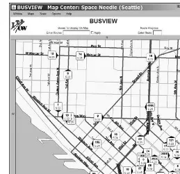
These same networks might also provide a variety of special data services to the local government and major subscribers. For example, the local natural gas, electric, and water utilities could add small Wi-Fi adapters to their meters and use the system to send readings once a month. And city buses might have transponders that report their locations to a central tracking system, like the one in Seattle at http://busview.org/busview_launch.jsp, as shown in Figure 2-8.
It’s not yet clear whether these city-wide Wi-Fi services will be able to overcome possible interference problems and competition from other wireless data alternatives, or whether they will attract enough business to remain viable. But if they do, any computer within the coverage area that has a Wi-Fi adapter should detect the signal and have access to a broadband Internet connection.
Wi-Fi was originally intended to be a wireless extension of a wired LAN, so the distances between Wi-Fi base stations and the computers that commu-nicate through them are limited to about 100 feet (35 meters) indoors or up to 300 feet (100 meters) outdoors, assuming there are no obstructions between the access point and the computer. When 802.11n equipment becomes available, it will sup-port connections between computers and base stations at least as far apart as the older Wi-Fi versions. There are ways to extend the range of a Wi-Fi signal, but those techniques require special equipment and careful installation.
Figure 2-8: Wireless technology tracks city buses in Seattle and reports locations on a website.
Cellular Mobile Wireless Services
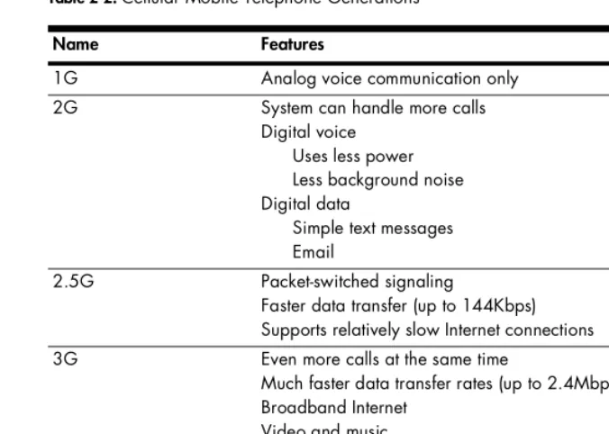
Several broadband wireless data services are extensions of cellular mobile telephone technology. You might see them described as 3G services because they’re based on the third generation of cellular telephone technology. If you have been using a mobile telephone for more than a year or two, you probably remember that the earliest phones were only good for voice calls, but as each new generation was introduced, your mobile carrier offered more and better features. Table 2-2 describes the various generations.
Of course, computer technology has also been improving at the same time, so today’s 2.5G and 3G mobile telephones often incorporate enough computing power to allow them to double as pocket-size Internet terminals (as well as cameras and media players). And equally important, from the perspective of this book, broadband data adapters that use 2.5G and 3G technology can attach to a laptop or other portable computer and provide a direct wireless connection to the Internet through the same cellular telephone company that offers mobile telephone service.
Today, most cellular broadband wireless services offer credit card–size adapters that connect to your computer through the PC Card socket on the side of a laptop or into the front or back panel of a desktop computer. In another year or two, many new laptops will come with internal adapters and integrated antennas for both Wi-Fi and 3G wireless or WiMAX that mount directly on the motherboard, just as they contain internal Wi-Fi adapters and dial-up modems today.
NOTE Some cellular service providers also offer mobile telephones that can connect a computer to the Internet through a USB cable linked to the phone, but separate PC Card adapters are a lot more convenient and easy to use.
Table 2-2: Cellular Mobile Telephone Generations
Name Features
1G Analog voice communication only
2G System can handle more calls
Digital voice Uses less power Less background noise Digital data
Simple text messages Email
2.5G Packet-switched signaling
Faster data transfer (up to 144Kbps) Supports relatively slow Internet connections
3G Even more calls at the same time
Much faster data transfer rates (up to 2.4Mbps) Broadband Internet
Video and music
4G (not yet available) Based on Internet technology Packet signaling
Very high speed (100Mbps–1Gbps)