I N T E R N A T I O N A L U N I O N O F C R Y S TA L L O G R A P H Y T E X T S O N C R Y S TA L L O G R A P H Y
I U C r B O O K S E R I E S C O M M I T T E E
J. Bernstein,Israel G. R. Desiraju,India
J. R. Helliwell,UK T. Mak,China P. Müller,USA P. Paufler,Germany H. Schenk,The Netherlands
P. Spadon,Italy D. Viterbo (Chairman),Italy IUCr Monographs on Crystallography
1 Accurate molecular structures A. Domenicano, I. Hargittai, editors
2 P.P. Ewald and his dynamical theory of X-ray diffraction D.W.J. Cruickshank, H.J. Juretschke, N. Kato, editors 3 Electron diffraction techniques, Vol. 1
J.M. Cowley, editor
4 Electron diffraction techniques, Vol. 2 J.M. Cowley, editor
5 The Rietveld method R.A. Young, editor
6 Introduction to crystallographic statistics U. Shmueli, G.H. Weiss
7 Crystallographic instrumentation
L.A. Aslanov, G.V. Fetisov, J.A.K. Howard 8 Direct phasing in crystallography
C. Giacovazzo
9 The weak hydrogen bond G.R. Desiraju, T. Steiner
10 Defect and microstructure analysis by diffraction R.L. Snyder, J. Fiala and H.J. Bunge
11 Dynamical theory of X-ray diffraction A. Authier
12 The chemical bond in inorganic chemistry I.D. Brown
13 Structure determination from powder diffraction data
W.I.F. David, K. Shankland, L.B. McCusker, Ch. Baerlocher, editors 14 Polymorphism in molecular crystals
I N T E R N AT I O N A L U N I O N O F C RY S TA L L O G R A P H Y B O O K S E R I E S
15 Crystallography of modular materials G. Ferraris, E. Makovicky, S. Merlino
16 Diffuse x-ray scattering and models of disorder T.R. Welberry
17 Crystallography of the polymethylene chain: an inquiry into the structure of waxes D.L. Dorset
18 Crystalline molecular complexes and compounds: structure and principles F. H. Herbstein
19 Molecular aggregation: structure analysis and molecular simulation of crystals and liquids
A. Gavezzotti
20 Aperiodic crystals: from modulated phases to quasicrystals T. Janssen, G. Chapuis, M. de Boissieu
21 Incommensurate crystallography S. van Smaalen
22 Structural crystallography of inorganic oxysalts S.V. Krivovichev
23 The nature of the hydrogen bond: outline of a comprehensive hydrogen bond theory G. Gilli, P. Gilli
24 Macromolecular crystallization and crystal perfection N.E. Chayen, J.R. Helliwell, E.H.Snell
IUCr Texts on Crystallography 1 The solid state
A. Guinier, R. Julien
4 X-ray charge densities and chemical bonding P. Coppens
7 Fundamentals of crystallography, second edition C. Giacovazzo, editor
8 Crystal structure refinement: a crystallographer’s guide to SHELXL P. Müller, editor
9 Theories and techniques of crystal structure determination U. Shmueli
10 Advanced structural inorganic chemistry Wai-Kee Li, Gong-Du Zhou, Thomas Mak
11 Diffuse scattering and defect structure simulations: a cook book using the program DISCUS
R. B. Neder, T. Proffen
12 The basics of crystallography and diffraction, third edition C. Hammond
The Basics of
Crystallography
and
Diffraction
Third Edition
Christopher Hammond
Institute for Materials Research University of Leeds
I N T E R N AT I O N A L U N I O N O F C RY S TA L L O G R A P H Y
3
Great Clarendon Street, Oxfordox2 6dpOxford University Press is a department of the University of Oxford. It furthers the University’s objective of excellence in research, scholarship,
and education by publishing worldwide in Oxford New York
Auckland Cape Town Dar es Salaam Hong Kong Karachi Kuala Lumpur Madrid Melbourne Mexico City Nairobi New Delhi
Shanghai Taipei Toronto With offices in
Argentina Austria Brazil Chile Czech Republic France Greece Guatemala Hungary Italy Japan Poland Portugal Singapore South Korea Switzerland Thailand Turkey Ukraine Vietnam
Oxford is a registered trade mark of Oxford University Press in the UK and in certain other countries
Published in the United States by Oxford University Press Inc., New York
© Christopher Hammond 2009
First edition (1997) Second edition (2001)
Third edition (2009)
The moral rights of the author have been asserted Database right Oxford University Press (maker)
All rights reserved. No part of this publication may be reproduced, stored in a retrieval system, or transmitted, in any form or by any means,
without the prior permission in writing of Oxford University Press, or as expressly permitted by law, or under terms agreed with the appropriate
reprographics rights organization. Enquiries concerning reproduction outside the scope of the above should be sent to the Rights Department,
Oxford University Press, at the address above
You must not circulate this book in any other binding or cover and you must impose the same condition on any acquirer
British library catalogue in Publication Data Data available
Library of Congress Cataloging in Publication Data Data available
Typeset by Newgen Imaging Systems (P) Ltd., Chennai, India Printed in the UK
on acid-free paper by
CPI Antony Rowe, Chippenham, Wiltshire
ISBN 978–0–19–954644–2 (Hbk) ISBN 978–0–19–954645–9 (Pbk)
Preface to the First Edition (1997)
This book has grown out of my earlierIntroduction to Crystallographypublished in the Royal Microscopical Society’s Microscopy Handbook Series (Oxford University Press 1990, revised edition 1992). My object then was to show that crystallography is not, as many students suppose, an abstruse and ‘difficult’ subject, but a subject that is essentially clear and simple and which does not require the assimilation and memorization of a large number of facts. Moreover, a knowledge of crystallography opens the door to a better and clearer understanding of so many other topics in physics and chemistry, earth, materials and textile sciences, and microscopy.
In doing so I tried to show that the ideas of symmetry, structures, lattices and the architecture of crystals should be approached by reference to everyday examples of the things we see around us, and that these ideas were not confined to the pages of textbooks or the models displayed in laboratories.
The subject of diffraction flows naturally from that of crystallography because by its means—and in most cases only by its means—are the structures of materials revealed. And this applies not only to the interpretation of diffraction patterns but also to the interpretation of images in microscopy. Indeed, diffraction patterns of objects ought to be thought of as being as ‘real’, and as simply understood, as the objects themselves. One is, to use the mathematical expression, simply the transform of the other. Hence, in discussing diffraction, I have tried to emphasize the common aspects of the phenomena with respect to light, X-rays and electrons.
In Chapter 1 (Crystals and crystal structures) I have concentrated on the simplest examples, emphasizing how they are related in terms of the occupancy of atomic sites and how the structures may be changed by faulting. Chapter 2 (Two-dimensional patterns, lattices and symmetry) has been considerably expanded, partly to provide a firm basis for understanding symmetry and lattices in three dimensions (Chapters 3 and 4) but also to address the interests of students involved in two-dimensional design. Similarly in Chapter 4, in discussing point group symmetry, I have emphasized its practical relevance in terms of the physical and optical properties of crystals.
The reciprocal lattice (Chapter 6) provides the key to our understanding of diffraction, but as aconceptit stands alone. I have therefore introduced it separately from diffraction and hope that in doing so these topics will be more readily understood. In Chapter 7 (The diffraction of light) I have emphasized the geometrical analogy with electron diffraction and have avoided any quantitative analysis of the amplitudes and intensities of diffracted beams. In my experience the (sometimes lengthy) equations which are required cloud students’ perceptions of the basic geometrical conditions for constructive and destructive interference—and which are also of far more practical importance with respect, say, to the resolving power of optical instruments.
Chapter 8 describes the historical development of the geometrical interpretation of X-ray diffraction patterns through the work of Laue, the Braggs and Ewald. The diffrac-tion of X-rays and electrons from single crystals is covered in Chapter 9, but only in the case of X-ray diffraction are the intensties of the diffracted beams discussed.
vi Preface to the First Edition (1997)
nothing more than an extension of Bragg’s law. Finally, the important X-ray and electron diffraction techniques from polycrystalline materials are covered in Chapter 10.
The Appendices cover material that, for ease of reference, is not covered in the text. Appendix 1 gives a list of items which are useful in making up crystal models and provides the names and addresses of suppliers. A rapidly increasing number of crystallography programs are becoming available for use in personal computers and in Appendix 2 I have listed those which involve, to a greater or lesser degree, some ‘self learning’ element. If it is the case that the computer program will replace the book, then one might expect that books on crystallography would be the first to go! That day, however, has yet to arrive. Appendix 3 gives brief biographical details of crystallographers and scientists whose names are asterisked in the text. Appendix 4 lists some useful geometrical relationships. Throughout the book the mathematical level has been maintained at a very simple level and with few minor exceptions all the equations have been derived from first principles. In my view, students learn nothing from, and are invariably dismayed and perplexed by, phrases such as ‘it can be shown that’—without any indication or guidance ofhowit can be shown. Appendix 5 sets out all the mathematics which are needed.
Finally, it is my belief that students appreciate a subject far more if it is presented to them not simply as a given body of knowledge but as one which has been gained by the exertions and insight of men and women perhaps not much older than themselves. This therefore shows that scientific discovery is an activity in which they, now or in the future, can participate. Hence the justification for the historical references, which, to return to my first point, also help to show that science progresses, not by being made more complicated, but by individuals piecing together facts and ideas, and seeing relationships where vagueness and uncertainty existed before.
Preface to the Second Edition (2001)
In this edition the content has been considerably revised and expanded not only to provide a more complete and integrated coverage of the topics in the first edition but also to introduce the reader to topics of more general scientific interest which (it seems to me) flow naturally from an understanding of the basic ideas of crystallography and diffraction.
Chapter 1 is extended to show how some more complex crystal structures can be understood in terms of different faulting sequences of close-packed layers and also covers the various structures of carbon, including the fullerenes, the symmetry of which finds expression in natural and man-made forms and the geometry of polyhedra.
Preface to Third Edition (2009) vii Chapters 5 and 6 have been revised with the objective of making the subject-matter more readily understood and appreciated.
In Chapter 7 I briefly discuss the human eye as an optical instrument to show, in a simple way, how beautifully related are its structure and its function.
The material in Chapters 9 and 10 of the first edition has been considerably expanded and re-arranged into the present Chapters 9, 10 and 11. The topics of X-ray and neu-tron diffraction from ordered crystals, preferred orientation (texture or fabric) and its measurement are now included in view of their importance in materials and earth sciences.
The stereographic projection and its uses is introduced at the very end of the book (Chapter 12)—quite the opposite of the usual arrangement in books on crystallography. But I consider that this is the right place: for here the usefulness and advantages of the stereographic projection are immediately apparent whereas at the beginning it may appear to be merely a geometrical exercise.
Finally, following the work of Prof. Amand Lucas, I include in Chapter 10 a sim-ulation by light diffraction of the structure of DNA. There are, it seems to me, two landmarks in X-ray diffraction: Laue’s 1912 photograph of zinc blende and Franklin’s 1952 photograph of DNA and in view of which I have placed these ‘by way of symmetry’ at the beginning of this book.
Preface to Third Edition (2009)
I have considerably expanded Chapters 1 and 4 to include descriptions of a much greater range of inorganic and organic crystal structures and their point and space group sym-metries. Moreover, I now include in Chapter 2 layer group symmetry—a topic rarely found in textbooks but essential to an understanding of such familiar things as the patterns formed in woven fabrics and also as providing a link between two- and three-dimensional symmetry. Chapters 9 and 10 covering X-ray diffraction techniques have been (partially) updated and include further examples but I have retained descriptions of older techniques where I think that they contribute to an understanding of the geometry of diffraction and reciprocal space. Chapter 11 has been extended to cover Kikuchi and EBSD patterns and image formation in electron microscopy. A new chapter (Chapter 13) introduces the basic ideas of Fourier analysis in X-ray crystallography and image formation and hence is a development (requiring a little more mathematics) of the elementary treatment of those topics given in Chapters 7 and 9. The Appendices have been revised to include polyhedra in crystallography in order to complement the new material in Chapter 1 and the biographical notes in Appendix 3 have been much extended.
It may be noticed that many of the books listed in ‘Further Reading’ are very old. However, in many respects, crystallography is a ‘timeless’ subject and such books to a large extent remain a valuable source of information.
Acknowledgements
In the preparation of the successive editions of this book I have greatly benefited from the advice and encouragement of present and former colleagues in the University of Leeds who have appraised and discussed draft chapters or who have materially assisted in the preparation of the figures. In particular, I wish to mention Dr Andrew Brown, Professor Rik Brydson, Dr Tim Comyn, Dr Andrew Scott and Mr David Wright (Institute for Materials Research); Dr Jenny Cousens and Professor Michael Hann (School of Design); Dr Peter Evennett (formerly of the Department of Pure and Applied Biology); Dr John Lydon (School of Biological Sciences); the late Dr John Robertson (former Chairman of the IUCr Book Series Committee) and the late Dr Roy Shuttleworth (formerly of the Department of Metallurgy).
Dr Pam Champness (formerly of the Department of Earth Sciences, University of Manchester) read and advised me on much of the early draft manuscript; Mrs Kate Crennell (formerly Education Officer of the BCA) prepared several of the figures in Chapter 2; Professor István Hargittai (of the Budapest University of Technology and Economics) advised me on the work, and sought out biographical material, on A I Kitaigorodskii; Professor Amand Lucas (of the University of Namur and Belgian Royal Academy) allowed me to use his optical simulation of the structure of DNA and Dr Keith Rogers (of Cranfield University) advised me on the Rietveld method. Ms Melanie Johnstone and Dr Sonke Adlung of the Academic Division, Oxford University Press, have guided me in overall preparation and submission of the manuscript.
Many other colleagues at Leeds and elsewhere have permitted me to reproduce figures from their own publications, as have the copyright holders of books and journals. Individual acknowledgements are given in the figure captions.
I would like to thank Miss Susan Toon and Miss Claire McConnell for word processing the manuscript and for attending to my constant modifications to it and to Mr David Horner for his careful photographic work.
Finally, I recall with gratitude the great influence of my former teachers, in particular Dr P M Kelly and the late Dr N F M Henry.
The structure and content of the book have developed out of lectures and tutorials to many generations of students who have responded, constructively and otherwise, to my teaching methods.
C.H.
Institute for Materials Research University of Leeds
Contents
X-ray photograph of zinc blende(Friedrich, Knipping and von Laue, 1912) xiv X-ray photograph of deoxyribonucleic acid(Franklin and Gosling, 1952) xv
1
Crystals and crystal structures
1
1.1 The nature of the crystalline state 1
1.2 Constructing crystals from close-packed hexagonal layers of atoms 5
1.3 Unit cells of the hcp and ccp structures 6
1.4 Constructing crystals from square layers of atoms 9
1.5 Constructing body-centred cubic crystals 10
1.6 Interstitial structures 11
1.7 Some simple ionic and covalent structures 18
1.8 Representing crystals in projection: crystal plans 19
1.9 Stacking faults and twins 21
1.10 The crystal chemistry of inorganic compounds 26
1.10.1 Bonding in inorganic crystals 27
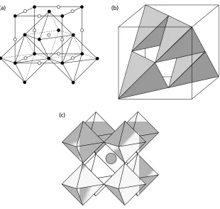
1.10.2 Representing crystals in terms of coordination polyhedra 29
1.11 Introduction to some more complex crystal structures 31
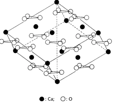
1.11.1 Perovskite (CaTiO3), barium titanate (BaTiO3) and related
structures 31
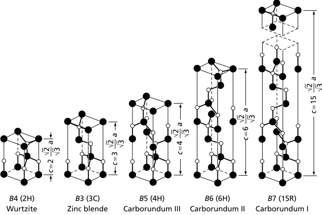
1.11.2 Tetrahedral and octahedral structures—silicon carbide and
alumina 33
1.11.3 The oxides and oxy-hydroxides of iron 35
1.11.4 Silicate structures 37
1.11.5 The structures of silica, ice and water 43
1.11.6 The structures of carbon 46
Exercises 53
2
Two-dimensional patterns, lattices and symmetry
55
2.1 Approaches to the study of crystal structures 55
2.2 Two-dimensional patterns and lattices 56
2.3 Two-dimensional symmetry elements 58
2.4 The five plane lattices 61
2.5 The seventeen plane groups 64
2.6 One-dimensional symmetry: border or frieze patterns 65
2.7 Symmetry in art and design: counterchange patterns 65
2.8 Layer (two-sided) symmetry and examples in woven textiles 73
2.9 Non-periodic patterns and tilings 77
x Contents
3
Bravais lattices and crystal systems
84
3.1 Introduction 84
3.2 The fourteen space (Bravais) lattices 84
3.3 The symmetry of the fourteen Bravais lattices: crystal systems 88 3.4 The coordination or environments of Bravais lattice points:
space-filling polyhedra 90
Exercises 95
4
Crystal symmetry: point groups, space groups,
symmetry-related properties and quasiperiodic
crystals
97
4.1 Symmetry and crystal habit 97
4.2 The thirty-two crystal classes 99
4.3 Centres and inversion axes of symmetry 100
4.4 Crystal symmetry and properties 104
4.5 Translational symmetry elements 107
4.6 Space groups 111
4.7 Bravais lattices, space groups and crystal structures 118
4.8 The crystal structures and space groups of organic compounds 121
4.8.1 The close packing of organic molecules 122
4.8.2 Long-chain polymer molecules 124
4.9 Quasiperiodic crystals or crystalloids 126
Exercises 130
5
Describing lattice planes and directions in crystals:
Miller indices and zone axis symbols
131
5.1 Introduction 131
5.2 Indexing lattice directions—zone axis symbols 132
5.3 Indexing lattice planes—Miller indices 133
5.4 Miller indices and zone axis symbols in cubic crystals 136
5.5 Lattice plane spacings, Miller indices and Laue indices 137
5.6 Zones, zone axes and the zone law, the addition rule 139
5.6.1 The Weiss zone law or zone equation 139
5.6.2 Zone axis at the intersection of two planes 139
5.6.3 Plane parallel to two directions 140
5.6.4 The addition rule 140
5.7 Indexing in the trigonal and hexagonal systems:
Weber symbols and Miller-Bravais indices 141
5.8 Transforming Miller indices and zone axis symbols 143
5.9 Transformation matrices for trigonal crystals with rhombohedral
lattices 146
5.10 A simple method for inverting a 3×3 matrix 147
Contents xi
6
The reciprocal lattice
150
6.1 Introduction 150
6.2 Reciprocal lattice vectors 150
6.3 Reciprocal lattice unit cells 152
6.4 Reciprocal lattice cells for cubic crystals 156
6.5 Proofs of some geometrical relationships using reciprocal
lattice vectors 158
6.5.1 Relationships betweena,b,canda∗,b∗,c∗ 158
6.5.2 The addition rule 159
6.5.3 The Weiss zone law or zone equation 159
6.5.4 d -spacing of lattice planes(hkl) 160
6.5.5 Angleρbetween plane normals (h1k1l1) and (h2k2l2) 160 6.5.6 Definition ofa∗,b∗,c∗in terms ofa,b,c 161 6.5.7 Zone axis at intersection of planes (h1k1l1) and (h2k2l2) 161 6.5.8 A plane containing two directions [u1v1w1] and [u2v2w2] 161
6.6 Lattice planes and reciprocal lattice planes 161
6.7 Summary 163
Exercises 164
7
The diffraction of light
165
7.1 Introduction 165
7.2 Simple observations of the diffraction of light 167
7.3 The nature of light: coherence, scattering and interference 172 7.4 Analysis of the geometry of diffraction patterns from gratings
and nets 174
7.5 The resolving power of optical instruments: the telescope, camera,
microscope and the eye 181
Exercises 190
8
X-ray diffraction: the contributions of Max von Laue,
W. H. and W. L. Bragg and P. P. Ewald
192
8.1 Introduction 192
8.2 Laue’s analysis of X-ray diffraction: the three Laue equations 193
8.3 Bragg’s analysis of X-ray diffraction: Bragg’s law 196
8.4 Ewald’s synthesis: the reflecting sphere construction 198
Exercises 202
9
The diffraction of X-rays
203
9.1 Introduction 203
9.2 The intensities of X-ray diffracted beams: the structure factor
xii Contents
9.3 The broadening of diffracted beams: reciprocal lattice points and
nodes 215
9.3.1 The Scherrer equation: reciprocal lattice points and nodes 216
9.3.2 Integrated intensity and its importance 220
9.3.3 Crystal size and perfection: mosaic structure and
coherence length 220
9.4 Fixedθ, varyingλX-ray techniques: the Laue method 221
9.5 Fixedλ, varyingθX-ray techniques: oscillation, rotation and
precession methods 223
9.5.1 The oscillation method 223
9.5.2 The rotation method 225
9.5.3 The precession method 226
9.6 X-ray diffraction from single crystal thin films and multilayers 229
9.7 X-ray (and neutron) diffraction from ordered crystals 233
9.8 Practical considerations: X-ray sources and recording techniques 237
9.8.1 The generation of X-rays in X-ray tubes 238
9.8.2 Synchrotron X-ray generation 239
9.8.3 X-ray recording techniques 240
Exercises 240
10 X-ray diffraction of polycrystalline materials
243
10.1 Introduction 243
10.2 The geometrical basis of polycrystalline (powder) X-ray
diffraction techniques 244
10.3 Some applications of X-ray diffraction techniques in
polycrystalline materials 252
10.3.1 Accurate lattice parameter measurements 252
10.3.2 Identification of unknown phases 253
10.3.3 Measurement of crystal (grain) size 256
10.3.4 Measurement of internal elastic strains 256
10.4 Preferred orientation (texture, fabric) and its measurement 257
10.4.1 Fibre textures 258
10.4.2 Sheet textures 259
10.5 X-ray diffraction of DNA: simulation by light diffraction 262
10.6 The Rietveld method for structure refinement 267
Exercises 269
11 Electron diffraction and its applications
273
11.1 Introduction 273
11.2 The Ewald reflecting sphere construction for electron diffraction 274
11.3 The analysis of electron diffraction patterns 277
Contents xiii 11.4.1 Determining orientation relationships between crystals 280 11.4.2 Identification of polycrystalline materials 281
11.4.3 Identification of quasiperiodic crystals 282
11.5 Kikuchi and electron backscattered diffraction (EBSD) patterns 283
11.5.1 Kikuchi patterns in the TEM 283
11.5.2 Electron backscattered diffraction (EBSD) patterns
in the SEM 287
11.6 Image formation and resolution in the TEM 288
Exercises 292
12 The stereographic projection and its uses
296
12.1 Introduction 296
12.2 Construction of the stereographic projection of a cubic crystal 299 12.3 Manipulation of the stereographic projection: use of the Wulff net 302
12.4 Stereographic projections of non-cubic crystals 305
12.5 Applications of the stereographic projection 308
12.5.1 Representation of point group symmetry 308
12.5.2 Representation of orientation relationships 310 12.5.3 Representation of preferred orientation (texture or fabric) 311
Exercises 314
13 Fourier analysis in diffraction and image formation
315
13.1 Introduction—Fourier series and Fourier transforms 315
13.2 Fourier analysis in crystallography 318
13.3 Analysis of the Fraunhofer diffraction pattern from a grating 323
13.4 Abbe theory of image formation 328
Appendix 1 Computer programs, models and model-building in
crystallography 333
Appendix 2 Polyhedra in crystallography 339
Appendix 3 Biographical notes on crystallographers and scientists mentioned
in the text 349
Appendix 4 Some useful crystallographic relationships 382
Appendix 5 A simple introduction to vectors and complex numbers and
their use in crystallography 385
Appendix 6 Systematic absences (extinctions) in X-ray diffraction and double
diffraction in electron diffraction patterns 392
Answers to Exercises 401
Further Reading 414
X-ray photograph of zinc blende
One of the eleven ‘Laue Diagrams’ in the paper submitted by Walter Friedrich, Paul Knipping and Max von Laue to the Bavarian Academy of Sciences and presented at its Meeting held on June 8th 1912—the paper which demonstrated the existence of internal atomic regularity in crystals and its relationship to the external symmetry.
X-ray photograph of deoxyribonucleic acid
The photograph of the ‘B’ form of DNA taken by Rosalind Franklin and Raymond Gosling in May 1952 and published, together with the two papers by J. D. Watson and F. H. C. Crick and M. H. F. Wilkins, A. R. Stokes and H. R. Wilson, in the 25 April issue ofNature,1953, under the heading ‘Molecular Structure of Nucleic Acids’.
The specimen is a fibre (axis vertical) containing millions of DNA strands roughly aligned parallel to the fibre axis and separated by the high water content of the fibre; this is the form adopted by the DNA in living cells. The X-ray beam is normal to the fibre and the diffraction pattern is characterised by four lozenges or diamond-shapes outlined by fuzzy diffraction haloes and separated by two rows or arms of spots radiating out-wards from the centre. These two arms are characteristic of helical structures and the angle between them is a measure of the ratio between the width of the molecule and the repeat-distance of the helix. But notice also the sequence of spots along each arm; there is a void where the fourth spot should be and this ‘missing fourth spot’ not only indicates that there are two helices intertwined but also the separation of the helices along the chain. Finally, notice that there are faint diffraction spots in the two side lozenges, but not in those above and below, an observation which shows that the sugar-phosphate ‘backbones’ are on the outside, and the bases on the inside, of the molecule.
1
Crystals and crystal structures
1.1
The nature of the crystalline state
The beautiful hexagonal patterns of snowflakes, the plane faces and hard faceted shapes of minerals and the bright cleavage fracture surfaces of brittle iron have long been recognized as external evidence of an internal order—evidence, that is, of the patterns or arrangements of the underlying building blocks. However, the nature of this internal order, or the form and scale of the building blocks, was unknown.
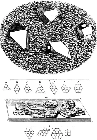
The first attempt to relate the external form or shape of a crystal to its underlying structure was made by Johannes Kepler∗who, in 1611, wrote perhaps the first treatise on geometrical crystallography, with the delightful title, ‘A New Year’s Gift or the Six-Cornered Snowflake’ (Strena Seu de Nive Sexangula).1 In this he speculates on the question as to why snowflakes always have six corners, never five or seven. He suggests that snowflakes are composed of tiny spheres or globules of ice and shows, in consequence, how the close-packing of these spheres gives rise to a six-sided figure. It is indeed a simple experiment that children now do with pennies at school. Kepler was not able to solve the problem as to why the six corners extend and branch to give many patterns (a problem not fully resolved to this day), nor did he extend his ideas to other crystals. The first to do so, and to consider the structure of crystals as a general problem, was Robert Hooke∗who, with remarkable insight, suggested that the different shapes of crystals which occur—rhombs, trapezia, hexagons, etc.—could arise from the packing together of spheres or globules. Figure 1.1 is ‘Scheme VII’ from his bookMicrographia, first published in 1665. The upper part (Fig. 1) is his drawing, from the microscope, of ‘Crystalline or Adamantine bodies’ occurring on the surface of a cavity in a piece of broken flint and the lower part (Fig. 2) is of ‘sand or gravel’ crystallized out of urine, which consist of ‘Slats or such-like plated Stones … their sides shaped intoRhombs, Rhomboeidsand sometimes intoRectanglesandSquares’. He goes on to show how these various shapes can arise from the packing together of ‘a company of bullets’ as shown in the inset sketchesA–L, which represent pictures of crystal structures which have been repeated in innumerable books, with very little variation, ever since. Also implicit in Hooke’s sketches is theLaw of the Constancy of Interfacial Angles; notice that the solid lines which outline the crystal faces are (except for the last sketch, L) all at 60˚ or 120˚ angles which clearly arise from the close-packing of the spheres. This law was first stated by Nicolaus Steno,∗a near contemporary of Robert Hooke in 1669, from simple
∗Denotes biographical notes available in Appendix 3.
1The Six-Cornered Snowflake, reprinted with English translation and commentary by the Clarendon Press,
2 Crystals and crystal structures
A
A
B
B
H I K L
C
C D
D E
E
F G
1 16
1 32 Fig. 2
a
b c
d
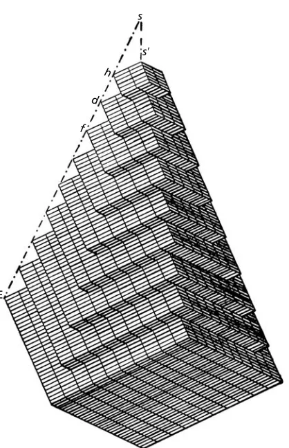
1.1 The nature of the crystalline state 3 observations of the angles between the faces of quartz crystals, but was developed much more fully as a general law by Rome de L’Isle∗in a treatise entitledCristallographiein 1783. He measured the angles between the faces of carefully-made crystal models and proposed that each mineral species therefore had an underlying ‘characteristic primitive form’. The notion that the packing of the underlying building blocks determines both the shapes of crystals and the angular relationships between the faces was extended by René Just Haüy.∗In 1784 Haüy showed how the different forms (or habits) of dog-tooth spar (calcite) could be precisely described by the packing together of little rhombs which he called ‘molécules intégrantes’ (Fig. 1.2). Thus the connection between an internal order and an external symmetry was established. What was not realized at the time was that an internal order could exist even though there may appear to be no external evidence for it.
E
f d
h s
s⬘
Fig. 1.2. Haüy’s representation of dog-tooth spar built up from rhombohedral ‘molécules integrantes’ (fromEssai d’une théorie sur la structure des cristaux,1784).
4 Crystals and crystal structures
It is only relatively recently, as a result primarily of X-ray and electron diffraction techniques, that it has been realized that most materials, including many biological materials, are crystalline or partly so. But the notion that a lack of external crystalline form implies a lack of internal regularity still persists. For example, when iron and steel become embrittled there is a marked change in the fracture surface from a rough, irregular ‘grey’ appearance to a bright faceted ‘brittle’ appearance. The change in properties from tough to brittle is sometimes vaguely thought to arise because the structure of the iron or steel has changed from some undefined amorphous or noncrystalline ‘grey’ state to a ‘crystallized’ state. In both situations, of course, the crystalline structure of iron is unchanged; it is simply the fracture processes that are different.
Given our more detailed knowledge of matter we can now interpret Hooke’s spheres or ‘bullets’ as atoms or ions, and Fig. 1.1 indicates the ways in which some of the simplest crystal structures can be built up. This representation of atoms as spheres does not, and is not intended, to show anything about their physical or chemical nature. The diameters of the spheres merely express their nearest distances of approach. It is true that these will depend upon the ways in which the atoms are packed together, and whether or not the atoms are ionized, but these considerations do not invalidate the ‘hard sphere’ model, which is justified, not as a representation of thestructureof atoms, but as a representation of the structures arising from thepacking togetherof atoms.
Consider again Hooke’s sketches A–L (Fig. 1.1). In all of these, except the last, L, the atoms are packed togetherin the same way;the differences in shape arise from the different crystal boundaries. The atoms are packed in aclose-packed hexagonalor honey-comb arrangement—the most compact way which is possible. By contrast, in thesquare arrangement of L there are larger voids or gaps (properly calledinterstices) between the atoms. This difference is shown more clearly in Fig. 1.3, where the boundaries of the (two-dimensional) crystals have been left deliberately irregular to emphasize the point
(a) (b)
1.2 Constructing crystals from hexagonal layers of atoms 5 that is the internal regularity, hexagonal, or square, not the boundaries (or external faces) which defines the structure of a crystal.
Now we shall extend these ideas to three dimensions by considering not one, but many, layers of atoms, stacked one on top of the other. To understand better the figures which follow, it is very helpful to make models of these layers (Fig. 1.3) to construct the three-dimensional crystal models (see Appendix 1).
1.2
Constructing crystals from close-packed hexagonal
layers of atoms
The simplest way of stacking the layers is to place the atom centres directly above one another. The resultant crystal structure is called thesimple hexagonal structure. There are, in fact, no examples of elements with this structure because, as the model building shows, the atoms in the second layer tend to slip into the ‘hollows’ or interstices between the atoms in the layer below. This also accords with energy considerations: unless electron orbital considerations predominate, layers of atoms stacked in this ‘close-packed’ way generally have the lowest (free) energy and are therefore most stable.
When a third layer is placed upon the second we see that there are two possibilities: when the atoms in the third layer slip into the interstices of the second layer they may either end up directly above the atom centres in the first layer or directly above the unoccupied interstices between the atoms in the first layer.
The geometry may be understood from Fig. 1.4, which shows a plan view of atom layers. A is the first layer (with the circular outlines of the atoms drawn in) and B is the second layer (outlines of the atoms not shown for clarity). In the first case the third layer goes directly above the A layer, the fourth layer over the B layer, and so on; the stacking sequence then becomes ABABAB … and is called thehexagonal close-packed (hcp) structure. The packing of idealized hard spheres predicts a ratio of interlayer atomic spacing to in-layer atomic spacing of√(2/3)(see Exercise 1.1) and although interatomic forces cause deviations from this ratio, metals such as zinc, magnesium and the low-temperature form of titanium have the hcp structure.
In the second case, the third layer of atoms goes above the interstices marked C and the sequence only repeats at the fourth layer, which goes directly above the first layer.
A A A A A
A B
C C
C C
C
B B
B B B
B
A A
A A A
A
6 Crystals and crystal structures
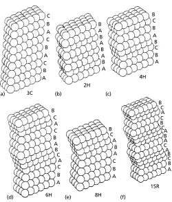
The stacking sequence is now ABCABC … and is called thecubic close-packed (ccp) structure.Metals such as copper, aluminium, silver, gold and the high-temperature form of iron have this structure. You may ask the question: ‘why is a structure which is made up of a three-layer stacking sequence of hexagonal layers calledcubicclose packed?’ The answer lies in the shape and symmetry of the unit cell, which we shall meet below. These labels for the layers A, B, C are, of course, arbitrary; they could be called OUP or RMS or any combination of three letters or figures. The important point is not the labelling of the layers but theirstacking sequence;a two-layer repeat for hcp and a three-layer repeat for ccp. Another way of ‘seeing the difference’ is to notice that in the hcp structure there are open channels perpendicular to the layers running through the connecting interstices (labelled C in Fig. 1.4). In the ccp structure there are no such open channels— they are ‘blocked’ or obstructed because of the ABCABC … stacking sequence.
Although the hcp and the ccp are the two most common stacking sequences of close-packed layers, some elements have crystal structures which are ‘mixtures’ of the two. For example, the actinide element americium and the lanthanide elements praseodymium, neodymium and samarium have the stacking sequence ABACABAC … a four-layer repeat which is essentially a combination of an hcp and a ccp stacking sequence. Furthermore, in some elements with nominally ccp or hcp stacking sequences nature sometimes ‘makes mistakes’ in model building and faults occur during crystal growth or under conditions of stress or deformation. For example, in a (predominantly) ccp crystal (such as cobalt at room temperature), the ABCABC … (ccp) type of stacking may be interrupted by layers with an ABABAB … (hcp) type of stacking. The extent of occurrence of thesestacking faultsand the particular combinations of ABCABC … and ABABAB … sequences which may arise depend again on energy considerations, with which we are not concerned. What is of crystallographic importance is the fact that stack-ing faults show how one structure (ccp) may be transformed into another (hcp) and vice versa. They can also be used in the representation of more complicated crystal structures (i.e. of more than one kind of atom), as explained in Sections 1.6 and 1.9 below.
1.3
Unit cells of the hcp and ccp structures
A simple and economical method is now needed to represent the hcp and ccp (and of course other) crystal structures. Diagrams showing the stacked layers of atoms with irregular boundaries would obviously look very confused and complicated—the greater the number of atoms which have to be drawn, the more complicated the picture. The models need to be ‘stripped down’ to the fewest numbers of atoms which show the essential structure and symmetry. Such ‘stripped-down’ models are called theunit cells of the structures.
1.3 Unit cells of the hcp and ccp structures 7
(a) (b)
A
A
A B
A
Fig. 1.5. Unit cells (a) of the simple hexagonal and (b) hcp structures.
A
A B C
B
C
(a)
(b) (c)
8 Crystals and crystal structures
The unit cell of the ccp structure is not so easy to see. There are, in fact, two possible unit cells which may be identified, a cubic cell described below (Fig. 1.6), which is almost invariably used, and a smaller rhombohedral cell (Fig. 1.7). Figure 1.6(a) shows three close-packed layers separately—two triangular layers of six atoms (identical to one of Hooke’ s sketches in Fig. 1.1)—and a third layer stripped down to just one atom. If we stack these layers in an ABC sequence, the result is as shown in Fig. 1.6(b): it is a cube with the bottom corner atom missing. This can now be added and the unit cell of the ccp structure, with atoms at the corners and centres of the faces, emerges. The unit cell is usually drawn in the ‘upright’ position of Fig. 1.6(c), and this helps to illustrate a very important point which may have already been spotted whilst model building with the close-packed layers. The close-packed layers lie perpendicular to the body diagonal of the cube, but as there are four different body diagonal directions in a cube, there are therefore four different sets of close-packed layers—not just the one set with which we started. Thus three further close-packed layers have been automatically generated by the ABCABC… stacking sequence. This does not occur in the hcp structure—try it and see! The cubic unit cell, therefore, shows thesymmetryof the ccp structure, a topic which
A
A B
C
B
C
(a)
(b) (c)
1.4 Constructing crystals from square layers of atoms 9 will be covered in Chapter 4. The alternative rhombohedral unit cell of the ccp structure may be obtained by ‘stripping away’ atoms from the cubic cell such that there are only eight atoms left—one at each of the eight corners—or it may be built up by stacking triangular layers of only three atoms instead of six (Fig. 1.7). Unlike the larger cell, this does not obviously reveal the cubic symmetry of the structure and so is much less useful.
1.4
Constructing crystals from square layers of atoms
It will be noticed that the atoms in the cube faces of the ccp structure lie in a square array like that in Fig. 1.3(b) and the ccp structure may be constructed by stacking these layers such that alternate layers lie in the square interstices marked X in Fig. 1.8(a). The models show how the four close-packed layers arise like the faces of a pyramid (Fig. 1.8(b)). If, on the other hand, the layers are all stacked directly on top of each other, a simple cubic structureis obtained (Fig. 1.8(c)). This is an uncommon structure for the same reason as the simple hexagonal one is uncommon. An example of an element with a simple cubic structure isα-polonium.
(a)
(b) (c)
10 Crystals and crystal structures
1.5
Constructing body-centred cubic crystals
The important and commonly occurringbody-centred cubic (bcc)structure differs from those already discussed in that it cannot be constructed either from hexagonal close-packed or square-close-packed layers of atoms (Fig. 1.3). The unit cell of the bcc structure is shown in Fig. 1.9. Notice how the body-centring atom ‘pushes’ the corner ones apart so that, on the basis of the ‘hard sphere’ model of atoms discussed above, they are not ‘in contact’ along the edges (in comparison with the simple cubic structure of Fig. 1.8(c), where they are in contact). In the bcc structure the atoms are in contact only along the body-diagonal directions. The planes in which the atoms are most (not fully) closely packed is the face-diagonal plane, as shown in Fig. 1.9(a), and in plan view, showing more atoms, in Fig. 1.9(b). The atom centres in the next layer go over the interstices marked B, then the third layer goes over the first layer, and so on—an ABAB … type of stacking sequence. The interstices marked B have a slight ‘saddle’ configuration, and model building will suggest that the atoms in the second layer might slip a small distance to one side or the other (indicated by arrows), leading to a distortion in the cubic structure. Whether such a situation can arise in real crystals, even on a small scale, is still a matter of debate. Metals such as chromium, molybdenum, the high-temperature form of titanium and the low-temperature form of iron have the bcc structure.
Finally, notice the close similarity between the layers of atoms in Figs 1.3(a) and 1.9(b). With only small distortions, e.g. closing of the gaps in Fig. 1.9(b), the two layers become geometrically identical and some important bcc ccp and bcc hcp transformations are thought to occur as a result of distortions of this kind. For example, when iron is quenched from its high-temperature form (ccp above 910˚C) to transform to its low-temperature (bcc) form, it is found that the set of the close-packed and closest-packed layers and close-packed directions are approximately parallel.
(a) (b)
1.6 Interstitial structures 11
1.6
Interstitial structures
The different stacking sequences of one size of atom discussed in Sections 1.2 and 1.5 are not only useful in describing the crystal structures in many of the elements, where all the atoms are identical to one another, but can also be used to describe and explain the crystal structures of a wide range of compounds of two or more elements, where there are atoms of two or more different sizes. In particular, they can be applied to those compounds in which ‘small’ atoms or cations fit into the interstices between ‘large’ atoms or anions. The different structures of very many compounds arise from the different numbers and sizes of interstices which occur in the simple hexagonal, hcp, ccp, simple cubic and bcc structures and also from the ways in which the small atoms or cations distribute themselves among these interstices. These ideas can, perhaps, be best understood by considering the types, sizes and numbers of interstices which occur in the ccp and simple cubic structures.
In the ccp structure there are two types and sizes of interstice into which small atoms or cations may fit. They are best seen by fitting small spheres into the interstices between two-close-packed atom layers (Fig. 1.4). Consider an atom in a B layer which fits into the hollow or interstice between three A layer atoms: beneath the B atom is an interstice which is surrounded at equal distances by four atoms—three in the A layer and one in the B layer. These four atoms surround or‘coordinate’the interstice in the shape of a tetrahedron, hence the nametetrahedral intersticeortetrahedral interstitial site,i.e. where a small interstitial atom or ion may be situated. The position of one such site in the ccp unit cell is shown in Fig. 1.10(a) and diagrammatically in Fig. 1.10(b).
The other interstices between the A and B layers (Fig. 1.4) are surrounded or coordi-nated by six atoms, three in the A layer and three in the B layer. These six atoms surround the interstice in the shape of an octahedron; hence the nameoctahedral intersticeor octahedral interstitial site.The positions of several atoms or ions in octahedral sites in a ccp unit cell are shown in Fig. 1.10(c) and diagrammatically, showing one octahedral site, in Fig. 1.10(d).
Now the diameters, or radii, of atoms or ions which can just fit into these interstices may easily be calculated on the basis that atoms or ions are spheres of fixed diameter— the ‘hard sphere’ model. The results are usually expressed as aradius ratio,rX/rA; the ratio of the radius (or diameter) of the interstitial atoms, X, to that of the large atoms, A, with which they are in contact. In the ccp structure,rX/rAfor the tetrahedral sites is 0.225 and for the octahedral sites it is 0.414. These radius ratios may be calculated with reference to Fig. 1.11. Figure 1.11(a) shows a tetrahedron, as in Fig. 1.10(b) outlined within a cube; clearly the centre of the cube is also the centre of the tetrahedron. The face-diagonal of the cube, or edge of the tetrahedron, along which the A atoms are in contact is of length 2rA. Hence the cube edge is of length 2rAcos 45=√2rAand the body-diagonal is of length√6rA. The interstitial atom X lies at the mid-point of the body diagonal and is in contact with a corner atom A.
HencerX+rA=½√6rA=1.225rA; whencerX =0.225rA.
12 Crystals and crystal structures
(b) (a)
(c) (d)
a√3
/
4Metal atoms
Tetrahedral interstices
Metal atoms
Octahedral interstices a
/
√2a
/
√2 a/
2Fig. 1.10. (a) An atom in a tetrahedral interstitial site,rX/rA=0.225 within the ccp unit cell and (b)
geometry of a tetrahedral site, showing the dimensions of the tetrahedron in terms of the unit cell edge lengtha. (c) Atoms or ions in some of the octahedral interstitial sites,rX/rA =0.414 within the ccp
unit cell and (d) geometry of an octahedral site, showing the dimensions of the octahedron in terms of the unit cell edge lengtha. (FromThe Structure of Metals,3rd edn, by C. S. Barrett and T. B. Massalski, Pergamon, 1980.)
are in contact, is of length 2rA and the diagonal along which the X and A atoms are in contact is of length 2√2rA.
Hence 2rX+2rA =2√2rA; whencerX=0.414rA.
1.6 Interstitial structures 13
2rA
2r
A
(a) (b)
Fig. 1.11. (a) A tetrahedral interstitial site X within a tetrahedron of four A atoms (shown as small filled circles for clarity) outlined within a cube, (b) A plan view of an octahedral interstitial site X with four surrounding A atoms (plus one above and one below X). The centres of the A atoms are shown as solid circles for clarity.
(a) (b) : Cs+ : Cl–
Fig. 1.12. (a) Cubic interstitial site,rX/rA=0.732, within the simple cube unit cell and (b) the CsC1
structure (ions not to scale).
are in contact along the cube edge, which is of length 2rAand the body diagonal, along which the atoms A and X are in contact, is of length 2√3rA.
HencerX+rA=½2√3rA; whence rX=0.732rA.
14 Crystals and crystal structures
is ‘shared’ by seven other cells, there is therefore one atom per cell—a ratio of 1:1. In the unit cell of the ccp structure (Fig. 1.10(c)), the octahedral sites are situated at the midpoints of each edge and in the centre. As each edge is shared by three other cells there are four octahedral sites per cell, i.e. twelve edges divided by four (number shared), plus one (centre). There are also four atoms per cell, i.e. eight corners divided by eight (number shared), plus six faces divided by two (number shared), again giving a ratio of 1:1. The tetrahedral sites in the ccp structure (Fig. 1.10(a) and (b)) are situated between a corner and three face-centring atoms, i.e. eight tetrahedral sites per unit cell, giving a ratio of 1:2.
It is a useful exercise to determine also the types, sizes and proportions of interstitial sites in the hcp, bcc and simple hexagonal structures. The hcp structure presents no problem; for the ‘hard sphere’ model with an interlayer to in-layer atomic ratio of√(2/3)
(Section 1.2) the interstitial sites are identical to those in ccp. It is only the distribution or ‘stacking sequence’ of the sites, like that of the close-packed layers of atoms, which is different.
In the bcc structure there are octahedral sites at the centres of the faces and mid-points of the edges (Figs 1.13(a) and (b)) and tetrahedral sites situated between the centres of the faces and mid-points of each edge (Figs 1.13(c) and (d)). Note, however, that both the octahedron and tetrahedron of the coordinating atoms do not have edges of equal length. The octahedron, for example, is ‘squashed’ in one direction and two of the coordinating atoms are closer to the centre of the interstice than are the other four.
It is very important to take this into account since the radius ratios are determined by the A atoms which are closer to the centre of the interstitial site and not those which are further away. For the octahedral interstitial site the four A atoms which are further away lie in a square (Fig. 1.13(b)), just as the case for those surrounding the octahedral interstitial site in the ccp structure (Fig. 1.10(d)), but it is not these atoms, but the two atoms in the ‘squashed’ direction in Fig. 1.13(b) which determine the radius ratio. These are at a closer distancea/2 from the interstitial site whereais the cube edge length. Since in the bcc structure the atoms are in contact along the body diagonal, length√3a, then 4rA =√3a.
HencerX+rA=a/2=2rA/√3, whencerX=0.154rA.
This is a very small site—smaller than the tetrahedral interstitial site (Fig. 1.13(c) and (d))—which has a radius ratio,rX/rA=0.291 (see Exercise 1.2).
1.6 Interstitial structures 15
(b) (a)
(d) (c)
a√3
/
2a√3
/
2a√5
/
4a
a
/
√2a
/
2Metal atoms
Metal atoms
Tetrahedral interstices Octahedral interstices
Fig. 1.13. (a) Octahedral interstitial sites,rX/rA=0.154, (b) geometry of the octahedral interstitial
sites, (c) tetrahedral interstitial sitesrX/rA=0.291, and (d) geometry of the tetrahedral interstitial sites
in the bcc structure, (b) and (d) show the dimensions of the octahedron and tetrahedron in terms of the unit cell edge lengtha(from Barrett and Massalski, loc. cit.).
others, is about 258 pm but that in the bcc structure, where each atom is surrounded by eight others, is about 248 pm—a contraction in going from twelve- to eight-fold coordination of about 4 per cent.
16 Crystals and crystal structures
(a) (b)
(c)
: N : Ti
: H : Ti
: Ti : H
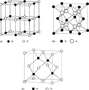
Fig. 1.14. (a) TiN structure (isomorphous with NaC1), (b) TiH2structure (isomorphous with CaF2)
and (c) TiH structure (isomorphous with sphalerite or zinc blende, ZnS or gallium arsenide, GaAs) (from
An Introduction to Crystal Chemistry,2nd edn, by R. C. Evans, Cambridge University Press, 1964).
1.6 Interstitial structures 17
(a) AI B (b) W C
Fig. 1.15. (a) A1B2structure, (b) WC structure.
In TiH2(Fig. 1.14(b)), the titanium atoms are also in an fcc array and the hydrogen atoms occupy all the tetrahedral sites, the ratio being of course 1:2. In TiH (Fig. 1.14(c)) the hydrogen atoms are again situated in the tetrahedral sites, but only half of these sites are occupied. Notice that in these interstitial compounds the fcc arrangement of the titanium atoms isnotthe same as their arrangement in the elemental form which is bcc (high temperature form) or hcp (low temperature form). In fact, interstitialcompounds based on a bcc packing of metal atoms are not known to exist; bcc metals such as vanadium, tungsten or iron (low temperature form) form interstitial compounds in which the metal atoms are arranged in an fcc pattern (e.g. VC), a simple hexagonal pattern (e.g. WC) or more complicated patterns (e.g. Fe3C). Hence although as mentioned in Section 1.2, no elements have the simple hexagonal structure in which the close-packed layers are stacked in an AAA … sequence directly on top of one another (Fig. 1.5(a)), the metal atoms in some metal carbides, nitrides, borides, etc., are stacked in this way, the carbon, nitrogen, boron, etc., atoms being situated in some or all of the interstices between the metal atoms. The interstices are halfway between the close-packed (or nearly close-packed) layers and are surrounded or coordinated by six atoms—not, however, as described above in the form of an octahedron but in the form of a triangular prism. In the A1B2structure all these sites are occupied (Fig. 1.15(a)) and in the WC structure only half are occupied (Fig. 1.15(b)).
18 Crystals and crystal structures
steel. In contrast, a much greater amount of carbon can enter the (uniform) octahedral interstitial sites in the ccp (high temperature) form of iron (called austenite)—1 carbon atom in about 10 iron atoms. The carbon atoms are still oversize, but the distortion is a uniform expansion and the hardening effect is much less.
1.7
Some simple ionic and covalent structures
The ideas presented in Section 1.6 above can be used to describe and explain the crystal structures of many simple but important ionic and covalent compounds, in particular many metal halides, sulphides and oxides. Although the metal atoms or cations are smaller than the chlorine, oxygen, sulphur, etc. atoms or anions, radius ratio consid-erations are only one factor in determining the crystal structures of ionic and covalent compounds and they are not usually referred to as interstitial compounds even though the pattern or distribution of atoms in the unit cells may be exactly the same. For exam-ple, the TIN structure (Fig. 1.14(a)) is isomorphous with the NaC1 structure. Similarly, the TiH2structure (Fig. 1.14(b)) is identical to the Li2O structure and the TiH structure (Fig. 1.14(c)) is isomorphous with ZnS (zinc blende or sphalerite) and GaAs (gallium arsenide) structure.
Unlike the fcc NaCl or TiN structure, structures based on an hcp packing of ions or atoms with all the octahedral interstitial sites occupied only occur in a distorted form. The frequently given example is nickel arsenide (niccolite, NiAs). The arsenic atoms are stacked in theABAB … hcp sequence but with an interlayer spacing rather larger than that for close packing (see answer to Exercise 1.1) and the Ni atoms occupy all the (distorted) octahedral interstitial sites. These are all ‘C’ sites between the ABAB … layers (see Fig. 1.4) and so the nickel atoms are stacked one above the other in a simple hexagonal packing sequence (Fig. 1.5(a))—they approach each other so closely that they are, in effect, nearest neighbours. Several sulphides (TeS, CoS, NiS, VS) all have the NiAs structure but there are no examples of oxides.
For a similar reason, structures based on the hcp packing of ions or atoms with all the tetrahedral sites occupied do not occur; there is no (known) such hcp intersititial structure corresponding to the fcc Li2O structure. This is a consequence of the distribution of tetrahedral sites which occur in ‘pairs’ perpendicular to the close packed planes, above and below which are either A or B layer atoms. The separation of these sites is only one-quarter the hexagonal unit cell height (see Exercise 1.1) and both sites cannot be occupied by interstitial ions or atoms at the same time. However, half the interstitial sites can be occupied, one example of such a structure being wurtzite, the hexagonal form of ZnS, described below.
1.8 Representing crystals in projection: crystal plans 19 Examples of ionic structures based on the simple cubic packing of anions are CsC1 and CaF2(fluorite). In CsC1 all the cubic interstitial sites are occupied by caesium cations (Fig. 1.12(b)) but in fluorite only half the sites are occupied by the calcium cations. The resulting unit cell is not just one simple cube of fluorine anions, but a larger cube with a cell side double that of the simple cube and containing therefore 2×2×2=8 cubes, four of which contain calcium cations and four of which are empty.
The distribution of the small calcium cations in the cubic sites is such that they form an fcc array and the fluorite structure can be represented alternatively as an fcc array of calcium cations with all the tetrahedral sites occupied by fluorine anions. It is identical, in terms of the distribution of ionic sites, to the structure of TiH2or Li2O (Fig. 1.14(b)), except that the positions of the cations and anions are reversed; hence Li2O is said to have theantifluorite structure. However, these differences, although in principle quite simple, may not be clear until we have some better method of representing the atom/ion positions in crystals other than the sketches (or clinographic projections) used in Figs. 1.10–1.15.
1.8
Representing crystals in projection: crystal plans
The more complicated the crystal structure and the larger the unit cell, the more difficult it is to visualize the atom or ion positions from diagrams or photographs of models— atoms or ions may be hidden behind others and therefore not seen. Another form of representation, thecrystal planorcrystal projection,is needed, which shows precisely the atomic or ionic positions in the unit cell. The first step is to specify axesx,yandz from a common origin and along the sides of the cell (see Chapter 5). By convention the ‘back left-hand corner’ is chosen as the origin, thez-axis ‘upwards’, they-axis to the right and thex-axis ‘forwards’, out of the page. The atomic/ionic positions or coordinates in the unit cell are specified as fractions of the cell edge lengths in the orderx, y, z.Thus in the bcc structure the atomic/ionic coordinates are (000) (the atom/ion at the origin) and121212(the atom/ion at the centre of the cube). As all eight corners of the cube are equivalent positions(i.e. any of the eight corners can be chosen as the origin), there is no need to write down atomic/ionic coordinates (100), (110), etc.; (000) specifiesallthe corner atoms, and the two-coordinates (000) and121212represent the two atoms/ions in the bcc unit cell. In the fcc structure, with four atoms/ions per unit cell, the coordinates are(000),12120,12012,01212.
Crystal projections or plans are usually drawn perpendicular to the z-axis, and Fig. 1.16(a) and (b) are plans of the bcc and fcc structure, respectively. Note that only the zcoordinates are indicated in these diagrams; thexandycoordinates need not be written down because they are clear from the plan. Similarly, nozcoordinates are indicated for all the corner atoms because all eight corners are equivalent positions in the structure, as mentioned above.
20 Crystals and crystal structures
Fig. 1.16. Plans of (a) bcc structure, (b) ccp or fcc structure, (c) Li2O (antifluorite) structure, (d) CaF2
(fluorite) structure.
Fig. 1.17. Alternative unit cells of the perovskite ABO3structure.
the fluorine anions in the fluorite structure. The alternative fluorite unit cell, made up of eight simple cubes (see Section 1.7), is drawn by shifting the origin of the axes in Fig. 1.16(c) to the ion at the141414site and relabelling the coordinates. The result is shown in Fig. 1.16(d).
1.9 Stacking faults and twins 21 Fig. 1.17(a) and (b) show the same crystal structure (perovskite, CaTiO3). They look different because the origins of the cells have been chosen to coincide with different atoms/ions.
1.9
Stacking faults and twins
As pointed out in Sections 1.2 and 1.7, the close packing of atoms (in metals and alloys) and anions (in ionic and covalent structures) may depart from the ABCABC … (ccp or fcc) or ABAB … (hcp or hexagonal) sequences: ‘nature makes mistakes’ and may do so in a number of ways. First, stacking faults may occur during crystallization from the melt or magma: second, they may occur during the solid state processes or recrystalliza-tion, phase transitions and crystal growth (i.e. during the heating and cooling of metals and alloys, ceramics and rocks); and third, they may occur during deformation. The mechanisms of faulting have been most widely studied, and are probably most easily understood in the simple case of metals in which there is no (interstitial) distribution of cations to complicate the picture. It is a study of considerable importance in metallurgy because of the effects of faulting on the mechanical and thermal properties of alloys— strength, work-hardening, softening temperatures and so on. However, this should not leave the impression that faulting is of lesser importance in other materials.
Consider first the ccp structure (or, better, have your close-packed raft models to hand). Three layers are stacked ABC (Fig. 1.4). Now the next layer should again by A; instead place it in the B layer position, where it fits equally well into the ‘hol-lows’ between the C layer atoms. This is the only alternative choice and the stacking sequence is now ABCB. Now, when we add the next layer we have two choices: either to place it in an A layer or in a C layer position. Now continue with our interrupted ABC … stacking sequence. In the first case we have the sequence ABCBABC … and in the second sequence ABCBCABC … In both cases it can be seen that there are layers which are in an hcp type of stacking sequence—but is there any difference between them, apart from the mere labelling of atom layers? Yes, there is a difference, which may be explained in two ways. If you examine the first sequence you will see that it is as if the mis-stacked B layer had beeninserted into the ABCABC … sequence and this is called an extrinsic stacking fault, whereas in the second case it is as if an A layer had beenremovedfrom the ABCABC … sequence, and this is called anintrinsic stacking fault. However, this explanation, although it is the basis of the names intrin-sicandextrinsic,is not very satisfactory. In order to understand better the distinction between stacking faults of different types (and indeed different stacking sequences in general), a completely different method of representing stacking sequences needs to be used.
You will recall (Section 1.2) that the labels for the layers are arbitrary and that it is the stackingsequencewhich is important; clearly then, some means of representing the sequence, rather than the layers themselves, is required. This requirement has been provided by F.C.Frank∗and is named after him—the Frank notation. Frank proposed that each step in the stacking sequence A→ B →C →A … should be represented
22 Crystals and crystal structures
by a little ‘upright’ triangle, and that each step in the stacking sequence, C→B→ A→C … should be represented by a little ‘inverted’triangle∇. Here are some examples, showing both the ABC … etc. type of notation for the layers and the Frank notation for the sequence of stacking of the layers. Note that the triangles comebetweenthe close packed layers, representing the stackingsequencebetween them.
A B C A B C A B C C B A C B A C B A Two fcc sequences
∇ ∇ ∇ ∇ ∇ ∇ ∇ ∇
A B A B A B A B C B C B C B C B Two hcp sequences
∇ ∇ ∇ ∇ ∇ ∇ ∇
A B C B A B C A B C B C A B C Extrinsic (left) and
∇ ∇ ∇ intrinsic (right)
stacking faults
Notice that the ccp (or fcc) stacking sequence is represented either by a sequence of upright triangles, or by a sequence of inverted ones—you could of course convert one to the other by simply turning your stack of close-packed layers upside down. However, the distinction is less arbitrary than this. An fcc crystal may grow, or be deformed (as explained below), such that the stacking sequence reverses, as indicated in Fig. 1.18 which shows the close-packed layers ‘edge on’ and both their ABC … etc. andor
∇ labels. Such a crystal is said to be twinned and the twin plane is that at which the stacking sequence reverses. Note that the crystal on one side of the twin plane is a mirror reflection of the other, just like the pair of hands in Fig. 4.5(b).
The hcp stacking sequence is represented by alternate upright and inverted triangles— and the sequence is unchanged if the stack of close-packed layers is turned upside down. Hence twinning on the close-packed planes is not possible in the hcp structure—it is as
A
Twin plane B
C A B C
B A
C B
A