MELSEC FX Family
Programmable Logic Controllers
Beginners Manual
FX
1S
, FX
1N
,
FX
2N
, FX
2NC
,
FX
3U
The texts, illustration, diagrams and examples in this manual are provided for information purposes only.
They are intended as aids to help explain the installation, operation, programming and use of the programmable logic controllers
of the MELSEC FX1S, FX1N, FX2N,FX2NC and FX3U series.
If you have any questions about the installation and operation of any of the products described in this manual please contact your local sales office or distributor (see inside back cover). You can find the latest information and answers to frequently asked
questions on our website atwww.mitsubishi-automation.com.
MITSUBISHI ELECTRIC EUROPE BV reserves the right to make changes to this manual or the technical specifications of its products at any time without notice.
Beginner’s Manual for the programmable logic controllers of the MELSEC FX family FX1S, FX1N, FX2N, FX2NCund FX3U
Art. no.: 166388
Safety Guidelines
For use by qualified staff only
This manual is only intended for use by properly trained and qualified electrical technicians who are fully acquainted with the relevant automation technology safety standards. All work with the hardware described, including system design, installation, configuration, mainten-ance, service and testing of the equipment, may only be performed by trained electrical techni-cians with approved qualifications who are fully acquainted with all the applicable automation technology safety standards and regulations. Any operations or modifications to the hardware and/or software of our products not specifically described in this manual may only be performed by authorised Mitsubishi Electric staff.
Proper use of the products
The programmable logic controllers of the FX1S, FX1N, FX2N, FX2NCand FX3Useries are only intended for the specific applications explicitly described in this manual. All parameters and settings specified in this manual must be observed. The products described have all been designed, manufactured, tested and documented in strict compliance with the relevant safety standards. Unqualified modification of the hardware or software or failure to observe the war-nings on the products and in this manual may result in serious personal injury and/or damage to property. Only peripherals and expansion equipment specifically recommended and appro-ved by Mitsubishi Electric may be used with the programmable logic controllers of the FX1S, FX1N, FX2NFX2NCand FX3Useries.
All and any other uses or application of the products shall be deemed to be improper. Relevant safety regulations
All safety and accident prevention regulations relevant to your specific application must be observed in the system design, installation, configuration, maintenance, servicing and testing of these products. The regulations listed below are particularly important in this regard. This list does not claim to be complete, however; you are responsible for being familiar with and conforming to the regulations applicable to you in your location.
쎲 VDE Standards – VDE 0100
Regulations for the erection of power installations with rated voltages below 1000 V – VDE 0105
Operation of power installations – VDE 0113
Electrical installations with electronic equipment – VDE 0160
Electronic equipment for use in power installations – VDE 0550/0551
Regulations for transformers – VDE 0700
Safety of electrical appliances for household use and similar applications – VDE 0860
Safety regulations for mains-powered electronic appliances and their accessories for household use and similar applications.
쎲 Fire safety regulations
쎲 Accident prevention regulations – VBG Nr.4
Electrical systems and equipment
Safety warnings in this manual
In this manual warnings that are relevant for safety are identified as follows:
P
DANGER:Failure to observe the safety warnings identified with this symbol can result in health and injury hazards for the user.
E
WARNING:Failure to observe the safety warnings identified with this symbol can result in damage to the equipment or other property.
General safety information and precautions
The following safety precautions are intended as a general guideline for using PLC systems together with other equipment. These precautions must always be observed in the design, installation and operation of all control systems.
P
DANGER:Safety Guidelines
쎲 Observe all safety and accident prevention regulations applicable to your spe-cific application. Always disconnect all power supplies before performing installation and wiring work or opening any of the assemblies, components and devices.
쎲 Assemblies, components and devices must always be installed in a shockproof housing fitted with a proper cover and fuses or circuit breakers.
쎲 Devices with a permanent connection to the mains power supply must be inte-grated in the building installations with an all-pole disconnection switch and a suitable fuse.
쎲 Check power cables and lines connected to the equipment regularly for breaks and insulation damage. If cable damage is found immediately disconnect the equipment and the cables from the power supply and replace the defective cab-ling.
쎲 Before using the equipment for the first time check that the power supply rating matches that of the local mains power.
쎲 Take appropriate steps to ensure that cable damage or core breaks in the signal lines cannot cause undefined states in the equipment.
쎲 You are responsible for taking the necessary precautions to ensure that pro-grams interrupted by brownouts and power failures can be restarted properly and safely. In particular, you must ensure that dangerous conditions cannot occur under any circumstances, even for brief periods.
쎲 EMERGENCY OFF facilities conforming to EN 60204/IEC 204 and VDE 0113 must remain fully operative at all times and in all PLC operating modes. The EMERGENCY OFF facility reset function must be designed so that it cannot ever cause an uncontrolled or undefined restart.
쎲 You must implement both hardware and software safety precautions to prevent the possibility of undefined control system states caused by signal line cable or core breaks.
Contents
Contents
1 Introduction
1.1 About this Manual . . . .1-1 1.2 More Information . . . .1-1
2 Programmable Logic Controllers
2.1 What is a PLC? . . . .2-1 2.2 How PLCs Process Programs . . . .2-2 2.3 The MELSEC FX Family . . . .2-4 2.4 Selecting the Right Controller . . . .2-5 2.5 Controller Design . . . .2-6 2.5.1 Input and output circuits . . . .2-6 2.5.2 Layout of the MELSEC FX1S base units . . . 2-6 2.5.3 Layout of the MELSEC FX1N base units . . . 2-7 2.5.4 Layout of the MELSEC FX2N base units . . . 2-7 2.5.5 Layout of the MELSEC FX2NC base units . . . 2-8 2.5.6 Layout of the MELSEC FX3U base units . . . 2-8 2.5.7 PLC components glossary . . . .2-9
3 An Introduction to Programming
Contents
3.4.10Generating pulses . . . .3-18 3.4.11Master control function (MC and MCR instructions) . . . 3-19 3.4.12Inversion of an Operation Result. . . 3-20 3.5 Safety First! . . . .3-21 3.6 Programming PLC Applications. . . .3-23 3.6.1 An alarm system . . . .3-23 3.6.2 A rolling shutter gate . . . .3-28
4 Devices in Detail
4.1 Inputs and Outputs . . . .4-1 4.2 Relays . . . .4-3 4.2.1 Special relays . . . .4-3 4.3 Timers . . . .4-4 4.4 Counters . . . .4-7 4.5 Registers . . . .4-9 4.5.1 Data registers . . . .4-9 4.5.2 Special registers . . . .4-10 4.5.3 File registers . . . .4-11 4.6 Programming Tips for Timers and Counters . . . 4-11 4.6.1 Specifying timer and counter setpoints indirectly . . . 4-11 4.6.2 Switch-off delay . . . .4-14 4.6.3 Delayed make and break. . . .4-15 4.6.4 Clock signal generators . . . .4-16
5 More Advanced Programming
Contents
5.3 Compare Instructions . . . .5-15 5.3.1 The CMP instruction . . . .5-15 5.3.2 Comparisons within logic operations. . . 5-17 5.4 Math Instructions . . . .5-20 5.4.1 Addition . . . .5-21 5.4.2 Subtraction . . . .5-22 5.4.3 Multiplication . . . .5-23 5.4.4 Division . . . .5-24 5.4.5 Combining math instructions. . . 5-25
6 Expansion Options
1
Introduction
1.1
About this Manual
This manual will help you to familiarise yourself with the use of the MELSEC FX family of pro-grammable logic controllers. It is designed for users who do not yet have any experience with programming programmable logic controllers (PLCs).
Programmers who already have experience with PLCs from other manufacturers can also use this manual as a guide for making the transition to the MELSEC FX family.
The symbol „쏔“ is used as a placeholder to identify different controllers in the same range. For
example, the designation "FX1S-10쏔-쏔쏔" is used to refer to all controllers whose name
begins with FX1S-10, i.e. FX1S-10 MR-DS, FX1S-10 MR-ES/UL, FX1S-10 MT-DSS and FX1S-10 MT-ESS/UL.
1.2
More Information
You can find more detailed information on the individual products in the series in the operating and installation manuals of the individual modules.
See the MELSEC FX Family Catalogue, art. no. 167840, for a general overview of all the con-trollers in the MELSEC FX family. This catalogue also contains information on expansion options and the available accessories.
For an introduction to using the programming software package see the GX Developer FX Beginner’s Manual, art. no.166391.
You can find detailed documentation of all programming instructions in the Programming Manual for the MELSEC FX family, art. no.132738and in the Programming Manual for the FX3U series, art. no.168591.
The communications capabilities and options of the MELSEC FX controllers are documented in detail in the Communications Manual, art. no.070143.
All Mitsubishi manuals and catalogues can be downloaded free of charge from the Mitsubishi website atwww.mitsubishi-automation.com.
2
Programmable Logic Controllers
2.1
What is a PLC?
In contrast to conventional controllers with functions determined by their physical wiring the functions of programmable logic controllers or PLCs are defined by a program. PLCs also have to be connected to the outside world with cables, but the contents of their program memory can be changed at any time to adapt their programs to different control tasks.
Programmable logic controllers input data, process it and then output the results. This process is performed in three stages:
쎲 an input stage, 쎲 a processing stage
and
쎲 an output stage
The input stage
The input stage passes control signals from switches, buttons or sensors on to the processing stage.
The signals from these components are generated as part of the control process and are fed to the inputs as logical states. The input stage passes them on to the processing stage in a pre-processed format.
The processing stage
In the processing stage the pre-processed signals from the input stage are processed and combined with the help of logical operations and other functions. The program memory of the processing stage is fully programmable. The processing sequence can be changed at any time by modifying or replacing the stored program.
The output stage
The results of the processing of the input signals by the program are fed to the output stage where they control connected switchable elements such as contactors, signal lamps, solenoid valves and so on.
Programmable Logic Controllers What is a PLC?
Programmable Logic Controller
Input Stage Processing Stage Output Stage
Contactors Switch
2.2
How PLCs Process Programs
A PLC performs its tasks by executing a program that is usually developed outside the control-ler and then transferred to the controlcontrol-ler’s program memory. Before you start programming it is useful to have a basic understanding of how PLCs process these programs.
A PLC program consists of a sequence of instructions that control the functions of the control-ler. The PLC executes these control instructions sequentially, i.e. one after another. The entire program sequence is cyclical, which means that it is repeated in a continuous loop. The time required for one program repetition is referred to as the program cycle time or period. Process image processing
The program in the PLC is not executed directly on the inputs and outputs, but on a “process image” of the inputs and outputs:
Input process image
At the beginning of each program cycle the system polls the signal states of the inputs and stores them in a buffer, creating a “process image” of the inputs.
How PLCs Process Programs Programmable Logic Controllers
.... .... .... Switch on PLC
Delete output memory
Input terminals
Process image of inputs
PLC program
Process image of outputs
Output terminals Transfer process imageto outputs Instruction 1 Instruction 2 Instruction 3
Instruction n Poll inputs and signal states and save them in the process
image of the inputs Input signals
Program execution
After this the program is executed, during which the PLC accesses the stored states of the inputs in the process image. This means that any subsequent changes in the input states will not be registered until thenextprogram cycle!
The program is executed from top to bottom, in the order in which the instructions were pro-grammed. Results of individual programming steps are stored and can be used during the cur-rent program cycle.
Output process image
Results of logical operations that are relevant for the outputs are stored in an output buffer – the output process image. The output process image is stored in the output buffer until the buffer is rewritten. After the values have been written to the outputs the program cycle is repeated. Differences between signal processing in the PLC and in hard-wired controllers In hard-wired controllers the program is defined by the functional elements and their connec-tions (the wiring). All control operaconnec-tions are performed simultaneously (parallel execution). Every change in an input signal state causes an instantaneous change in the corresponding output signal state.
In a PLC it is not possible to respond to changes in input signal states until the next program cycle after the change. Nowadays this disadvantage is largely compensated by very short pro-gram cycle periods. The duration of the propro-gram cycle period depends on the number and type of instructions executed.
Programmable Logic Controllers How PLCs Process Programs
M6
M2 M1 M8013 4
X000 X001 0
9
M0
Y000 M0
Y001 Store result Program execution
Process stored result
2.3
The MELSEC FX Family
The compact micro-controllers of the MELSEC FX series provide the foundation for building economical solutions for small to medium-sized control and positioning tasks requiring 10 to 256 integrated inputs and outputs in applications in industry and building services.
With the exception of the FX1S all the controllers of the FX series can be expanded to keep pace with the changes in the application and the user’s growing requirements.
Network connections are also supported. This makes it possible for the controllers of the FX family to communicate with other PLCs and controller systems and HMIs (Human-Machine Interfaces and control panels). The PLC systems can be integrated both in MITSUBISHI net-works as local stations and as slave stations in open netnet-works like PROFIBUS/DP.
In addition to this you can also build multi-drop and peer-to-peer networks with the controllers of the MELSEC FX family.
The FX1N, FX2N and FX3U have modular expansion capabilities, making them the right choice for complex applications and tasks requiring special functions like analog-digital and digital-analog conversion and network capabilities.
All the controllers in the series are part of the larger MELSEC FX family and are fully compati-ble with one another.
The MELSEC FX Family Programmable Logic Controllers
Specifications FX1S FX1N FX2N FX2NC FX3U
Max integrated
I/O points 30 60 128 96 80
Expansion capability
(max. possible I/Os) 34 132 256 256 384
Program memory
(steps) 2000 8000 16000 16000 64000
Cycle time per
log. instruction (µs) 0,55 – 0,7 0,55 – 0,7 0,08 0,08 0,065
No. of instructions (standard / step ladder / special function)
27 / 2 / 85 27 / 2 / 89 27 / 2 / 107 27 / 2 / 107 27 / 2 / 209
Max. special function
modules connectable — 2 8 4
2.4
Selecting the Right Controller
The base units of the MELSEC FX1S, FX1N and FX2N(C) series are available in a number of different versions with different power supply options and output technologies. You can choose between units designed for power supplies of 100–240 V AC, 24 V DC or 12–24 V DC, and between relay and transistor outputs. The controllers of the FX3U series are currently only available for AC power supply and with relay outputs.
To choose the right controller for your application you need to answer the following questions:
쎲 How many signals (external switch contacts, buttons and sensors) do you need to input? 쎲 What types of functions do you need to switch, and how many of them are there? 쎲 What power supply options are available?
쎲 How high are the loads that the outputs need to switch? Choose relay outputs for switching
high loads and transistor outputs for switching fast, trigger-free switching operations. Programmable Logic Controllers Selecting the Right Controller
Series I/Os Type No. of
inputs
No. of
outputs Power supply Output type
FX1S
24 V DC Transistor or relay
32 FX3U-32 MR/ES 16 16
48 FX3U-48 MR/ES 24 24
64 FX3U-64 MR/ES 32 32
2.5
Controller Design
All the controllers in the series have the same basic design. The main functional elements and assemblies are described in the glossary in section 2.5.7.
2.5.1
Input and output circuits
Theinput circuitsuse floating inputs. They are electrically isolated from the other circuits of the PLC with optical couplers. Theoutput circuitsuse either relay or transistor output techno-logy. The transistor outputs are also electrically isolated from the other PLC circuits with optical couplers.
The switching voltage at all the digital inputs must have a certain value (e.g. 24 V DC). This volt-age can be taken from the PLC’s integrated power supply unit. If the switching voltvolt-age at the inputs is less than the rated value (e.g. <24 V DC) then the input will not be processed. The maximum output currents are 2 A on 250 V three-phase AC and non-reactive loads with relay outputs and 0.5 A on 24 V DC and non-reactive loads.
2.5.2
Layout of the MELSEC FX
1Sbase units
Controller Design Programmable Logic Controllers
0 1 2 3
COM0 COM1COM2Y3 Y5
24V
2.5.3
Layout of the MELSEC FX
1Nbase units
2.5.4
Layout of the MELSEC FX
2Nbase units
Programmable Logic Controllers Controller Design
Protective cover
RUN/STOP switch Extension bus
Connection of the Slot for memory cassettes,
adapters and displays strip for digital outputs
Connection for
2.5.5
Layout of the MELSEC FX
2NCbase units
2.5.6
Layout of the MELSEC FX
3Ubase units
Controller Design Programmable Logic Controllers
Terminals for
RUN/STOP switch Extension bus(on side)
Battery
2.5.7
PLC components glossary
The following table describes the meaning and functionality of the single components und parts of a Mitsubishi PLC.
Programmable Logic Controllers Controller Design
Component Description
Connection for expansion adapter boards
Optional expansion adapter boards can be connected to this interface. A variety of diffe-rent adapters are available for all FX lines (except the FX2NC). These adapters extend the capabilities of the controllers with additional functions or communications interfaces. The adapter boards are plugged directly into the slot.
Connection for pro-gramming units
This connection can be used for connecting the FX-20P-E hand-held programming unit or an external PC or notebook with a programming software package (e.g. GX Devel-oper/FX).
EEPROM
Read/write memory in which the PLC program can be stored and read with the program-ming software. This solid-state memory retains its contents without power, even in the event of a power failure, and does not need a battery.
Memory cassette slot
Slot for optional memory cassettes. Inserting a memory cassette disables the controller’s internal memory – the controller will then only execute the program stored in the cassette.
Extension bus
Both additional I/O expansion modules and special function modules that add additional capabilities to the PLC system can be connected here. See Chapter 6 for an overview of the available modules.
Analog potentiometers
The analog potentiometers are used for setting analog setpoint values. The setting can be polled by the PLC program and used for timers, pulse outputs and other functions (see Section 4.6.1).
Service power supply
The service power supply (not for FX2NC) provides a regulated 24V DC power supply source for the input signals and the sensors. The capacity of this power supply depends on the controller model (e.g. FX1S and FX1N: 400mA; FX2N-16M쏔-쏔쏔through FX2N-32M쏔-쏔쏔: 250 mA, FX2N-48M쏔-쏔쏔through FX2N-64M쏔-쏔쏔: 460 mA)
Digital inputs
The digital inputs are used for inputting control signals from the connected switches, but-tons or sensors. These inputs can read the values ON (power signal on) and OFF (no power signal).
Digital outputs You can connect a variety of different actuators and other devices to these outputs, depending on the nature of your application and the output type.
LEDs for indicating the input status
These LEDs show which inputs are currently connected to a power signal, i.e. a defined voltage. When a signal is applied to an input the corresponding LED lights up, indicating that the state of the input is ON.
LEDs for indicating the output status
These LEDs show the current ON/OFF states of the digital outputs. These outputs can switch a variety of different voltages and currents depending on the model and output type.
LEDs for indicating the operating status
The LEDs RUN, POWER and ERROR show the current status of the controller. POWER shows that the power is switched on, RUN lights up when the PLC program is being exe-cuted and ERROR lights up when an error or malfunction is registered.
Memory battery
The battery protects the contents of the MELSELC PLC’s volatile RAM memory in the event of a power failure (FX2N, FX2NCand FX3U only). It protects the latched ranges for timers, counters and relays. In addition to this it also provides power for the integrated real-time clock when the PLC’s power supply is switched off.
RUN/STOP switch
3
An Introduction to Programming
A program consists of a sequence of program instructions. These instructions determine the functionality of the PLC and they are processed sequentially, in the order in which they were entered by the programmer. To create a PLC program you thus need to analyse the process to be controlled and break it up into steps that can be represented by instructions. A program instruction, represented by a line or “rung” in ladder diagram format, is the smallest unit of a PLC application program.
3.1
Structure of a Program Instruction
A program instruction consists of the instruction itself (sometimes referred to as a command) and one or more (in the case of applied instructions) operands, which in a PLC are references to devices. Some instructions are entered on their own without specifying any operands – these are the instructions that control program execution in the PLC.
Every instruction you enter is automatically assigned a step number that uniquely identifies its position in the program. This is important because it is quite possible to enter the same instruc-tion referring to the same device in several places in the program.
The illustrations below show how program instructions are represented in the Ladder Diagram (LD, left) and Instruction List (IL, right) programming language formats:
The instruction describeswhatis to be done, i.e. the function you want the controller to per-form. The operand or device is what you want to perform the functionon. Its designation con-sists of two parts, the device name and the device address:
Examples of devices:
See Chapter 4 for a detailed description of the available devices.
The specific device is identified by its address. For example, since every controller has multiple inputs you need to specify both the device name and the address in order to read a specific input.
An Introduction to Programming Structure of a Program Instruction
X0
DeviceInstruction
AND X0 Device Instruction
X 0
Device address Device name
Device name Type Function
X Input Input terminal on the PLC (e.g. connected to a switch) Y Output Output terminal on the PLC (e.g. for a contactor or lamp) M Relay A buffer memory in the PLC that can have two states, ON or OFF T Timer A “time relay” that can be used to program timed functions
C Counter A counter
3.2
Bits, Bytes and Words
As in all digital technology, the smallest unit of information in a PLC is a “bit”. A bit can only have two states: “0” (OFF or FALSE) and “1” (ON or TRUE). PLCs have a number of so-calledbit devicesthat can only have two states, including inputs, outputs and relays.
The next larger information units are the “byte”, which consists of 8 bits, and the “word”, which consists of two bytes. In the PLCs of the MELSEC FX families the data registers are “word devices”, which means that they can store 16-bit values.
Since a data register is 16 bits wide it can store signed values between -32,768 and +32,767 (see Chapter 3.3). When larger values need to be stored two words are combined to form a 32-bit long word, which can store signed values between -2,147,483,648 and +2,147,483,647. Counters make use of this capability, for example.
3.3
Number Systems
The PLCs of the MELSEC FX family use several different number systems for inputting and displaying values and for specifying device addresses.
Decimal numbers
The decimal number system is the system we use most commonly in everyday life. It is a “posi-tional base 10” system, in which each digit (position) in a numeral is ten times the value of the digit to its right. After the count reaches 9 in each position the count in the current position is returned to 0 and the next position is incremented by 1 to indicate the next decade (9à10, 99 à100, 199à1,000 etc).
– Base: 10
– Digits: 0, 1, 2, 3, 4, 5, 6, 7, 8, 9
In the MELSEC FX family of PLCs decimal numbers are used for entering constants and the setpoint values for timers and counters. Device addresses are also entered in decimal format, with the exception of the addresses of inputs and outputs.
Binary numbers
Like all computers a PLC can only really distinguish between two states, ON/OFF or 0/1. These “binary states” are stored in individual bits. When numbers need to be entered or displayed in other formats the programming software automatically converts the binary numbers into the other number systems.
– Base: 2 – Digits: 0 and 1
Bits, Bytes and Words An Introduction to Programming
0
0
0
0
0
0
0
0
0
0
0
0
0
0
0
0
1 Byte 1 Byte
1 Word
When binary numbers are stored in a word (see above) the value of each digit (position) in the word is one power of 2 higher than that of the digit to its right. The principle is exactly the same as in decimal representation, but with increments of 2 instead of 10 (see graphic):
* In binary values bit 15 is used to represent the sign (bit 15=0: positive value, bit 15=1: negative value)
To convert a binary value to a decimal value you just have to multiply each digit with a value of 1 by its corresponding power of 2 and calculate the sum of the results.
Example쑴 00000010 00011001 (binary)
00000010 00011001 (binary) = 1 x 29+ 1 x 24+ 1 x 23+ 1 x 20 00000010 00011001 (binary) = 512 + 16 + 8 + 1
00000010 00011001 (binary) = 537 (decimal)
Hexadecimal numbers
Hexadecimal numbers are easier to handle than binary and it is very easy to convert binary numbers to hexadecimal. This is why hexadecimal numbers are used so often in digital tech-nology and programmable logic controllers. In the controllers of the MELSEC FX family hexa-decimal numbers are used for the representation of constants. In the programming manual and other manuals hexadecimal numbers are always identified with an H after the number to avoid confusion with decimal numbers (e.g. 12345H).
– Base: 16
– Digits: 0, 1, 2, 3, 4, 5, 6, 7, 8, 9, A, B, C, D, E, F (the letters A, B, C, D, E and F represent the decimal values 10, 11, 12, 13, 14 and 15)
The hexadecimal system works in the same way as the decimal system – you just count to FH
(15) instead of to 9 before resetting to 0 and incrementing the next digit (FHà10H, 1FHà20H, 2FHà30H, FFHà100H etc). The value of digit is a power of 16, rather than a power of 10:
An Introduction to Programming Number Systems
0
Base 2 Notation Decimal Value Base 2 Notation Decimal Valuet
The following example illustrates why it is so easy to convert binary values hexadecimal values:
* Converting the 4-bit blocks to decimal values does not directly produce a value that corresponds to the complete 16-bit binary value! In contrast, the binary value can be converted directly to hexadecimal notation with exactly the same value as the binary value.
Octal numbers
Inputs X8 and X9 and outputs Y8 and Y9 do not exist on the base units of the MELSEC FX fam-ily. This is because the inputs and outputs of MELSEC PLCs are numbered using the octal number system, in which the digits 8 and 9 don’t exist. Here, the current digit is reset to 0 and the digit in the next position is incremented after the count reaches 7 (0 – 7, 10 – 17, 70 – 77, 100 – 107 etc).
– Base: 8
– Digits: 0, 1, 2, 3, 4, 5, 6, 7 Summary
The following table provides an overview of the four different number systems:
Number Systems An Introduction to Programming
Decimal notation Octal notation Hexadecimal notation Binary notation
0 0 0 0000 0000 0000 0000
1 1 1 0000 0000 0000 0001
2 2 2 0000 0000 0000 0010
3 3 3 0000 0000 0000 0011
4 4 4 0000 0000 0000 0100
5 5 5 0000 0000 0000 0101
6 6 6 0000 0000 0000 0110
7 7 7 0000 0000 0000 0111
8 10 8 0000 0000 0000 1000
9 11 9 0000 0000 0000 1001
10 12 A 0000 0000 0000 1010
11 13 B 0000 0000 0000 1011
12 14 C 0000 0000 0000 1100
13 15 D 0000 0000 0000 1101
14 16 E 0000 0000 0000 1110
15 17 F 0000 0000 0000 1111
16 20 10 0000 0000 0001 0000
: : : :
99 143 63 0000 0000 0110 0011
: : : :
1
1 1 1 0 1 1 0 1 0 1 1 0 0 1
1
15 5 11 9
F 5 B 9
Binary
Decimal*
3.4
The Basic Instruction Set
The instructions of the PLCs of the MELSEC FX family can be divided into two basic catego-ries, basic instructions and applied instructions, which are sometimes referred to as “applica-tion instruc“applica-tions”.
The functions performed by the basic instructions are comparable to the functions achieved by the physical wiring of a hard-wired controller. All controllers of the MELSEC FX family support the instructions in the basic instruction set, but the applied instructions supported vary from model to model (see Chapter 5).
Basic instruction set quick reference
An Introduction to Programming The Basic Instruction Set
Instruction Function Description Reference
LD Load Initial logic operation, polls for signal state “1” (normally open)
Chapter 3.4.1 LDI Load invers Initial logic operation, polls for signal state “0” (normally closed)
OUT Output instruction Assigns the result of a logic operation to a device Chapter 3.4.2 AND Logical AND Logical AND operation, polls for signal state “1”
Chapter 3.4.4 ANI AND NOT Logical AND NOT operation, polls for signal state “0”
OR Logical OR Logical OR operation, polls for signal state “1”
Chapter 3.4.5 ORI OR NOT Logical OR NOT operation, polls for signal state “0"
ANB AND Block Connects a parallel branch circuit block to the preceding parallel block, in
series. Chapter 3.4.6
ORB OR Block Connects a serial block of circuits to the preceding serial block, in parallel. LDP
Pulse signal instructions
Load Pulse, load on detection of rising edge of device signal pulse
Chapter 3.4.7 LDF Load Falling Pulse, load on falling device signal pulse
ANDP AND Pulse, logical AND on rising device signal pulse ANDF AND Falling Pulse, logical AND on falling device signal pulse
ORP OR Pulse, logical OR on rising device signal pulse ORF OR Falling Pulse, logical OR on falling device signal pulse
SET Set device Assigns a signal state that is retained even if after input condition is no
longer true Chapter 3.4.8
RST Reset device MPS
Store, read and delete intermediate operation results
Memory Point Store, store an operation result in the stack
Chapter 3.4.9 MRD Memory Read, read a stored operation result from the stack
MPP Memory POP, read a stored operation result and delete it from the stack
PLS
Pulse instructions
Pulse, sets a device for one operation cycle on the rising pulse of the input
condition (input turns ON) Chapter
3.4.10 PLF Pulse Falling, sets a device* for one operation cycle on the falling pulse ofthe input condition (input turns OFF)
MC Master Control Instructions for activating or deactivating the execution of defined parts of the program
Chapter 3.4.11 MCR Master Control Reset
INV Invert Inverts the result of an operation Chapter
3.4.1
Starting logic operations
A circuit in a program always begins with an LD- or LDI instruction. These instructions can be performed on inputs, relays, timers and counters.
For examples of using these instructions see the description of the OUT instruction in the next section.
3.4.2
Outputting the result of a logic operation
The OUT instruction can be used to terminate a circuit. You can also program circuits that use multiple OUT instructions as their result. This is not necessarily the end of the program, how-ever. The device set with the result of the operation using OUT can then be used as an input signal state in subsequent steps of the program.
Example (LD and OUT instructions)
These two instructions result in the following signal sequence:
The Basic Instruction Set An Introduction to Programming
Instruction Function Symbol GX Developer FX
OUT Output instruction, assigns the result of an operation to a device
X000
0 Y000
Ladder Diagram Instruction List
0 LD X000
1 OUT Y000
Y0 X0
OFF ON
OFF ON
t
(0) (1)
(0) (1)
The condition of the LD instruction (poll for signal state “1”) is true so the result of the operation is also true (“1”) and the output is set.
F5
F6
F7
Instruction Function Symbol GX Developer FX
LD
Load instruction, starts a logic operation and polls the specified device for signal state “1”
LDI
Example (LDI and OUT instructions)
Double assignment of relays or outputs
Never assign the result of an operation to the same device in more than one place in the program!
An Introduction to Programming The Basic Instruction Set
X005 X003
M10 X004
X001 You can solve this problem
with modification shown on the right. This takes all the required input conditions into account and sets the result correctly.
X000
0 Y000
Ladder Diagram Instruction List
0 LDI X000 1 OUT Y000
Y0 X0
t
(0) (1)
(0) (1) OFF
ON
OFF ON
The condition of the LDI instruction (poll for signal state “0”) is no longer true so the output is reset.
X005 X003
M10 M10 X004
X001 The program is executed
3.4.3
Using switches and sensors
Before we continue with the description of the rest of the instructions we should first describe how signals from switches, sensors and so on can be used in your programs.
PLC programs need to be able respond to signals from switches, buttons and sensors to per-form the correct functions. It is important to understand that program instructions can only poll the binary signal state of the specified input – irrespective of the type of input and how it is controlled.
Usually, switches with make contacts are used. Sometimes, however, break contacts are used for safety reasons – for example for switching off drives (see section 3.5).
The illustration below shows two program sequences in which the result is exactly the same, even though different switch types are used: When the switch is operated the output is set (switched on).
The Basic Instruction Set An Introduction to Programming
Y000
When a make contact is ope-rated the input is set (ON, sig-nal state “1”)
Break contact
When a break contact is ope-rated the input is reset (OFF, signal state “0”)
3.4.4
AND operations
Note that the programming software uses the same icons and function keys for the AND and ANI instructions as for the LD and LDI instructions. When you program in Ladder Diagram for-mat the software autofor-matically assigns the correct instructions on the basis of the insertion position.
When you program in Instruction List format remember that you can’t use the AND and ANI instructions at the beginning of circuit (a program line in ladder diagram format)! Circuits must begin with an LD or LDI instruction (see Chapter 3.4.1).
Example of an AND instruction
In the example output Y0 is only switched on when inputs X0andX1 arebothon:
An Introduction to Programming The Basic Instruction Set
Instruction Function Symbol GX Developer FX
AND Logical AND (AND operation with poll forsignal state “1” or ON)
ANI Logical AND NOT (AND operation withpoll for signal state “0” or OFF)
An AND operation is logically the same as a serial connection of two or more switches in an electrical circuit. Current will only flow if all the switches are closed. If one or more of the switches are open no current flows – the AND condition is false.
X000 0
X001
Y000
Ladder Diagram Instruction List
0 LD X000
1 AND X001 2 OUT Y000 AND instruction
Y0 X0
OFF ON
t
(0) (1)
(0) (1)
X1
(0) (1) OFF
ON
OFF ON
F5
Example of an ANI instruction
In the example output Y0 is only switched on when input X0 is onandinput X1 is off: The Basic Instruction Set An Introduction to Programming
Y0 X0
t
(0) (1)
(0) (1)
X1
(0) (1)
OFF ON OFF ON
OFF ON X000
0
X001
Y000
0 LD X000
1 ANI X001 2 OUT Y000 Instruction List Ladder Diagram
3.4.5
OR operations
Example of an OR instruction
In the example output Y0 is switched on wheneitherinput X0orinput X1 is on:
An Introduction to Programming The Basic Instruction Set
Instruction Function Symbol GX Developer FX
OR Logical OR (OR operation with poll forsignal state “1” or ON)
ORI Logical OR NOT (OR operation with pollfor signal state “0” or OFF)
An OR operation is logically the same as the parallel connection of multiple switches in an electrical circuit. As soon as any of the switches is closed current will flow. Current will only stop flowing when all the switches are open.
X000 0
X001
Y000
0 LD X000
1 OR X001
2 OUT Y000 Instruction List Ladder Diagram
OR instruction
Y0 X0
t (0)
(1)
(0) (1) X1
(0) (1)
OFF ON OFF ON
OFF ON
F5
Example of an ORI instruction
In the example output Y0 is switched on wheneitherinput X0 is onorinput X1 is off:
3.4.6
Instructions for connecting operation blocks
Although ANB- and ORB are PLC instructions they are only displayed and entered as connect-ing lines in the Ladder Diagram display. They are only shown as instructions in Instruction List format, where you must enter them with their acronyms ANB and ORB.
Both instructions are entered without devices and can be used as often as you like in a pro-gram. However, the maximum number of LD and LDI instructions is restricted to 8, which effec-tively also limits the number of ORB or ANB instructions you can use before an output instruc-tion to 8 as well.
The Basic Instruction Set An Introduction to Programming
Y0 X0
t (0)
(1)
(0) (1) X1
(0) (1)
OFF ON OFF ON
OFF ON
Instruction Function Symbol GX Developer FX
ANB AND Block (serial connection of blocks ofparallel operations/circuits)
ORB OR Block (parallel connection of blocksof serial operations/circuits)
F9
uF9
X0000
X001
Y000
0 LD X000
1 ORI X001 2 OUT Y000 Instruction List Ladder Diagram
Example of an ANB instruction
In this example output Y07 is switched on if input X00 is “1”,orif relay M2 is “0”andinput X01 is “0”,orif relay M10 is “1”.
Example of an ORB instruction
In this example output Y07 is switched on if input X00 is “1”andinput X01 is “0”,orif relay M2 is “0”andrelay M10 is “1”.
An Introduction to Programming The Basic Instruction Set
Y007 X000
0
M2
X001
M10
0 LD X000 1 ORI M2 2 LDI X001 3 OR M10 4 ANB
5 OUT Y007 Instruction List Ladder Diagram
ANB instruction
1stparallel connection (OR operation) 2ndparallel connection (OR operation)
ANB instruction connecting both OR operations
Y007 X000
0
M2
X001
M10
0 LD X000 1 ANI X001 2 LDI M2 3 AND M10 4 ORB
5 OUT Y007 Instruction List Ladder Diagram
ORB instruction
1stserial connection (AND operation) 2ndserial connection (AND operation)
3.4.7
Pulse-triggered execution of operations
In PLC programs you will often need to detect and respond to the rising or falling edge of a bit device’s switching signal. A rising edge indicates a switch of the device value from “0” to “1”, a falling edge indicates a switch from “1” to “0”.
During program execution operations that respond to rising and falling pulses only deliver a value of “1” when the signal state of the referenced device changes.
When do you need to use this? For example, suppose you have a conveyor belt with a sensor switch that activates to increment a counter every time a package passes it on the belt. If you don’t use a pulse-triggered function you will get incorrect results because the counter will increment by 1 in every program cycle in which the switch registers as set. If you only register the rising pulse of the switch signal the counter will be incremented correctly, increasing by 1 for each package.
Note Most applied instructions can also be executed by pulse signals. For details see chapter . 5). Evaluating a rising signal pulse
The Basic Instruction Set An Introduction to Programming
Instruction Function Symbol GX Developer FX
LDP Load Pulse, loads on the rising edge ofthe device’s signal
LDF Load Falling Pulse, loads on the fallingedge of the device’s signal
ANDP AND Pulse, logical AND operation on therising edge of the device’s signal
ANDF AND Falling Pulse, logical AND operationon the falling edge of the device’s signal
ORP OR Pulse, logical OR operation on therising edge of the device’s signal
ORF OR Falling Pulse, logical OR operationon the falling edge of the device’s signal
M0 X001
0
Ladder Diagram Instruction List
0 LDP X001 1 OUT M0
M0 X1
OFF ON
t
(0) (1)
0 1
Evaluating a falling signal pulse
With the exception of the pulse trigger characteristic the functions of the LDP, LDF, ANDP, ANDF, ORP and ORF instructions are identical to those of the LD, AND and OR instructions. This means that you can use pulse-trigger operations in your programs in exactly the same way as the conventional versions.
3.4.8
Setting and resetting devices
햲
The SET instruction can be used to set outputs (Y), relays (M) and state relays (S).
햳
The RST instruction can be used to reset outputs (Y), relays (M), state relays (S), timers (T), counters (C) and re-gisters (D, V, Z).
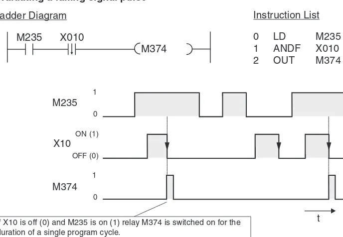
The signal state of an OUT instruction will normally only remain “1” as long as the result of the operation connected to the OUT instruction evaluates to “1”. For example, if you connect a pushbutton to an input and a lamp to the corresponding output and connect them with an LD and an OUT instruction the lamp will only remain on while the button remains pressed. The SET instruction can be used to use a brief switching pulse to switch an output or relay on (set) and leave them on. The device will then remain on until you switch it off (reset) with a RST instruction. This enables you to implement latched functions or switch drives on and off with pushbuttons. (Outputs are generally also switched off when the PLC is stopped or the power supply is turned off. However, some relays also retain their last signal state under these condi-tions – for example a set relay would then remain set.)
To enter a SET or RST instruction in Ladder Diagram format just click on the icon shown in the table above in GX Developer, or press the F8 key. Then enter the instruction and the name of the device you want to set or reset, for exampleSET Y1.
An Introduction to Programming The Basic Instruction Set
M374
M235 X010
0
Ladder Diagram Instruction List
0 LD M235 duration of a single program cycle.
Instruction Function Symbol GX Developer FX
SET Set a device
(assign signal state “1”) SET첸
RST Reset a device
(assign signal state “0”) RST첸
F8
This example is a program for controlling a pump to fill a container. The pump is controlled manually with two pushbuttons, ON and OFF. For safety reasons a break contact is used for the OFF function. When the container is full a level sensor automatically switches the pump off. The Basic Instruction Set An Introduction to Programming
X001
X003 X002
RST Y000
SET Y000
0
2
Ladder Diagram Instruction List
0 LD X001
1 SET Y000 2 LDI X002
3 OR X003
4 RST Y000 Pump
ON
Pump OFF
Level sensor
Pump
Pump X2
X1
M0
t
If the set and reset instructions for the same device both evaluate to “1” the last operation performed has priority. In this example that is the RST instruction, and so M0 remains off.
X001
X002
SET M0
RST M0
0
2
Ladder Diagram Instruction List
0 LD X001
1 SET M0
2 LD X002
3.4.9
Storing, reading and deleting operation results
The MPS, MRD and MPP instructions are used to store the results of operations and interme-diate values in a memory called the “stack”, and to read and delete the stored results. These instructions make it possible to program multi-level operations, which makes programs easier to read and manage.
When you enter programs in Ladder Diagram format these instructions are inserted automati-cally by the programming software. The MPS, MRD and MPP instructions are only actually shown when you display your program in Instruction List format, and they must also be entered manually when you program in this format.
To make the advantage of these instructions clearer the example below shows the same pro-gram sequence propro-grammed without MPS, MRD and MPP:
When you use this approach you must program the devices (X0 in this example) repeatedly. This results in more programming work, which can make quite a difference in longer programs and complex circuit constructions.
In the last output instruction you must use MPP instead of MRD to delete the stack. You can use multiple MPS instructions to create operations with up to 11 levels. For more examples of how to use the MPS, MRD and MPP instructions see the Programming Manual for the FX Family. An Introduction to Programming The Basic Instruction Set
Instruction Function Symbol GX Developer FX
MPS Memory Point Store, stores the result ofan operation — —
MRD Memory Read, reads a stored operationresult — —
MPP Memory POP, reads a stored operationresult and deletes it — —
X000 X001
Ladder Diagram Instruction List
3.4.10
Generating pulses
* PLC and PLF instructions can be used to set outputs (Y) and relays (M).
These instructions effectively convert a static signal into a brief pulse, the duration of which depends on the length of the program cycle. If you use PLS instead of an OUT instruction the signal state of the specified device will only be set to “1” for a single program cycle, specifically during the cycle in which the signal state of the device before the PLS instruction in the circuit switches from “0” to “1” (rising edge pulse).
The PLF instruction responds to a falling edge pulse and sets the specified device to “1” for a single program cycle, during the cycle in which the signal state of the device before the PLF instruction in the circuit switches from “1” to “0” (falling edge pulse).
To enter a PLS or PLF instruction in Ladder Diagram format click in the GX Developer toolbar on the tool icon shown above or pressF8. Then enter the instruction and the corresponding device to be set in the dialog, e.g. PLS Y2.
The Basic Instruction Set An Introduction to Programming
Instruction Function Symbol GX Developer FX
PLS
Pulse, sets an device* for the duration of a single program cycle on the rising edge of the switching pulse of the input condi-tion / device
PLS첸
PLF
Pulse Falling, sets a device* for the dura-tion of a single program cycle on the fal-ling edge of the switching pulse of the input condition / device
PLF첸
Ladder Diagram Instruction List
0 LD X000
X0 The rising edge of the device X0signal triggers the function.
Relays M0 and M1 are only switched on for the duration of a single program cycle.
3.4.11
Master control function (MC and MCR instructions)
햲
The MC instruction can be used on outputs (Y) and relays (M). n: N0 through N7
햳
n: N0 through N7
The Master Control Set (MC) and Reset (MCR) instructions can be used to set conditions on the basis of which individual program blocks can be activated or deactivated. In Ladder Dia-gram format a Master Control instruction functions like a switch in the left-hand bus bar that must be closed for the following program block to be executed.
In the example above the program lines between the MC and MCR instructions are only exe-cuted when input X001 is on.
The section of the program to be executed can be specified with the nesting address N0 through N7, which allows you to enter multiple MC instructions before the closing MCR instruc-tion. (See the FX Programming Manual for an example of nesting.) Addressing a Y or M device specifies a make contact. This contact activates the program section when the input condition for the MC instruction evaluates true.
An Introduction to Programming The Basic Instruction Set
Instruction Function Symbol GX Developer FX
MC
Master Control, sets a master control condition, marking the beginning of a
첸
MCR
Master Control Reset, resets a master control condition, marking the end of a
F8
The “switch” does not have to be programmed manually and it is only actually displayed during program execution in Monitor mode.
If the input condition of the MC instruction evaluates false the states of the devices between the MC and MCR instructions change as follows:
– Latched timers and counters and devices that are controlled with SET an RST instructions retain their current state.
– Unlatched timers and devices that are controlled with OUT instructions are reset. (See chapter 4 for details on these timers and counters.)
3.4.12
Inversion of an Operation Result
An INV instruction inverts the operation result up to just before the INV instruction, and does not require device number specification.
– If the result of an operation is "1", it becomes "0" after execution of the INV instruction. – If the result of an operation is "0", it becomes "1" after execution of the INV instruction.
The above example produces the following signal sequence:
The INV instruction can be used when you need to invert the result of a complex operation. It can be used in the same position as the AND and ANI instructions.
The INV instruction cannot be used at the beginning of an operation (circuit) like an LD, LDI, LDP or LDF instruction.
The Basic Instruction Set An Introduction to Programming
Instruction Function Symbol GX Developer FX
INV Invert, reverses the result of an operation
Y000
X001 X002
0
Ladder Diagram Instruction List
0 LD X001
1 AND X002 2 INV
3 OUT Y000 INV instruction
Y000 X001
t
0 1
0 1
X002
0 1
0 1
Operation result before the INV instruction
3.5
Safety First!
PLCs have many advantages over hard-wired controllers. However, when it comes to safety it is important to understand that you cannot trust a PLC blindly.
Emergency OFF devices
It is essential to ensure that errors in the control system or program cannot cause hazards for staff or machines. Emergency OFF devices must remain fully functional even when the PLC is not working properly – for example to switch off the power to the PLC outputs if necessary. Never implement an Emergency OFF switch solely as an input that is processed by the PLC, with the PLC program activating the shutdown. This would be much too risky.
Safety precautions for cable breaks
You must also take steps to ensure safety in the event that the transmission of signals from the switches to the PLC are interrupted by cable breaks. When switching equipment on and off via the PLC always use switches or pushbuttons with make contacts for switching on and with break contacts for switching off.
This ensures that if there is a cable break the drive is switched off automatically and it is not possible to activate the drive. In addition to this, switching off has priority because it is pro-cessed by the program after the switch on instruction.
Interlock contacts
If you have two outputs that should never both be switched on at the same time – for example outputs for selecting forward or reverse operation for a motor – the interlock for the outputs must also be implemented with physical contacts in the contactors controlled by the PLC. This is necessary because only an internal interlock is possible in the program and an error in the PLC could cause both outputs to be activated at the same time.
An Introduction to Programming Safety First!
EMERG.
In this example the contactor for a drive sys-tem can also be switched off manually with an Emergency OFF switch.
Motor ON
Automatic shutdown
When a PLC is used to control motion sequences in which hazards can arise when compo-nents move past certain points additional limit switches must be installed to interrupt the move-ment automatically. These switches must function directly and independently of the PLC. See Chapter 3.6.2. for an example of such an automatic shutdown facility.
Output signal feedback
Generally, the outputs of PLCs are not monitored. When an output is activated the program assumes that the correct response has taken place outside the PLC. In most cases no addi-tional facilities are required. However, in critical applications you should also monitor the out-put signals with the PLC – for example when errors in the outout-put circuit (wire breaks, seized contacts) could have serious consequences for safety or system functioning.
Safety First! An Introduction to Programming
X000 X001
COM Y000 X002
Y001 In the example on the right a make contact in
contactor K1 switches input X002 on when out-put Y000 is switched on. This allows the pro-gram to monitor whether the output and the connected contactor are functioning properly. Note that this simple solution does not check whether the switched equipment is functioning properly (for example if a motor is really turn-ing). Additional functions would be necessary to check this, for example a speed sensor or a voltage load monitor.
+24 V
K1 K2
K1 K2
K1
X000 X001
COM Y000 X002
Y001 The example on the right shows such an
3.6
Programming PLC Applications
Programmable logic controllers provide an almost unlimited number of ways to link inputs with outputs. Your task is to choose the right instructions from the many supported by the control-lers of the MELSEC FX family to program a suitable solution for your application.
This chapter provides two simple examples that demonstrate the development of a PLC appli-cation from the definition of the task to the finished program,.
3.6.1
An alarm system
The first step is to have a clear concept of what you want to do. This means that you need to take a “bottom-up” approach and write a clear description of what it is you want the PLC to do. Task description
The objective is to create an alarm system with several alarm circuits and a delay function for arming and disarming the system.
– The system will be armed with a key switch, with a 20-second delay between turning the switch and activation. This provides enough time for the user to leave the house without tripping the alarm. During this delay period a display will show whether the alarm circuits are closed.
– An alarm will be triggered when one of the circuits is interrupted (closed-circuit system, also triggers an alarm when a circuit is sabotaged). In addition to this we want to show which circuit triggered the alarm.
– When an alarm is triggered a siren and a blinking alarm lamp are activated after a delay of 10 seconds. (The acoustic and visual alarms are activated after a delay to make it possible to disarm the system after entering the house. This is also why we want to use a special lamp to show that the system is armed.)
– The siren will only be sounded for 30 seconds, but the alarm lamp will remain activated until the system is disarmed.
– A key-operated switch will also be used to deactivate the alarm system. Assignment of the input and output signals
The next step is to define the input and output signals we need to process. On the basis of the specifications we know that we are going to need 1 key-operated switch and 4 alarm lamps. In addition to this we need at least 3 inputs for the alarm circuits and 2 outputs for the siren and the blinking alarm lamp. This makes a total of 4 inputs and 6 outputs. Then we assign these signals to the inputs and outputs of the PLC:
An Introduction to Programming Programming PLC Applications
Function Name Adress Remarks
Input
Arm system S1 X1 Make contact (key-operated switch)
Alarm circuit 1 S11, S12 X2
Break contacts (an alarm is triggered when the input has the signal state “0”)
Alarm circuit 2 S21, S22 X3
Alarm circuit 3 S31, S32 X4
Output
Display “system armed” H0 Y0
The outputs functions are activated when the corresponding outputs are switched on (set). For example, if Y1 is set the acoustic alarm will sound.
Programming
Now we can start writing the program. Whether relay devices are going to be needed and if so how many usually only becomes clear once you actually start programming. What is certain in this project is that we are going to need three timers for important functions. If we were using a hard-wired controller we would use timer relays for this. In a PLC you have programmable elec-tronic timers (see Chapter 4.3). These timers can also be defined before we start programming:
Next we can program the individual control tasks:
쎲 Delayed arming of the alarm system
When the key-operated switch is turned to ON the delay implemented with timer T0 starts to run. After 20 seconds (K200 = 200 x 0.1s = 20s) the indicator lamp connected to output Y000 lights up, indicating that the system is armed.
쎲 Monitor alarm circuits and trigger alarm signal
Output Y000 is polled in this routine to check whether the alarm system is armed. You could also use a relay here that would then be set and reset together with Y000. An interruption of an alarm circuit will only set relay M1 (indicating that an alarm has been triggered) if the alarm sys-tem is actually armed. In addition to this outputs Y003 through Y005 are used to indicate which Programming PLC Applications An Introduction to Programming
Function Adress Remarks
Timer
Arming delay T0 Time: 20 seconds
Alarm triggering delay T1 Time: 10 seconds Siren activation duration T2 Time: 30 seconds
0
Ladder Diagram Instruction List
0 LD X001
Ladder Diagram Instruction List
쎲 Alarm activation delay
When an alarm is triggered (M1 switches to “1”) the 10s delay timer starts. After the 10 seconds T1 then starts timer T2, which is set to 30 seconds, and the siren activation time begins.
쎲 Alarm display (switch on siren and rotating beacon)
The siren is activated after the 10s activation delay (T1) and remains on while timer T2 is run-ning. After the end of the 30s activation period (T2) the siren deactivates. The rotating beacon is also switched on after the 10s delay. The following illustration shows the signal sequence generated by this section of the program:
An Introduction to Programming Programming PLC Applications
T2 T1
T1 26
29
Y001
Y002
Ladder Diagram Instruction List
26 LD T1 27 ANI T2 28 OUT Y001 29 LD T1 30 OUT Y002
T2 T1
Y1 M1
10 s
t
OFF ON 0 1
0 1
30 s
0 1
Y2
OFF ON
M1
T1 18
22
T1
T2 K100
K300
Ladder Diagram Instruction List
18 LD M1
19 OUT T1 K100 22 LD T1
쎲 Resetting all outputs and the relay
When the alarm system is switched off with the key-operated switch all the outputs used by the program and the relay M1 are all reset. If an alarm was triggered the interrupted alarm circuit which was released until the system was switched off is displayed.
Programming PLC Applications An Introduction to Programming
X001
31 Y000
Y001
Y002
Y003
Y004
Y005
M1 RST
RST
RST
RST
RST
RST
RST
Ladder Diagram Instruction List
Connection of the PLC
The sketch below shows how easy it is to implement this alarm system with a PLC of the FX family. The example shows an FX1N-14MR.
An Introduction to Programming Programming PLC Applications
S1
S/S 0 V N
PE
H1 H2 H3 H4
H0 E1
L1
S21
S11 S31
S32 S22
S12
MITSUBISHI
POWER RUN ERROR
FX -14MR1S
0 1 2 3 4 5 6 7
0 1 2 3 4 5
IN 100-240
VAC
14MR -ES/UL
L N
S/S X0
X1 X2
X3 X4
X5 X6
X7
OUT
24V COM0 Y0 0V
COM1 Y1
COM2 Y2
Y3 Y4
3.6.2
A rolling shutter gate
Task description
We want to implement a control system for a warehouse’s rolling shutter gate that will enable easy operation from both outside and inside. Safety facilities must also be integrated in the system.
쎲 Operation
– It must be possible to open the gate from outside with the key-operated switch S1 and to close it with pushbutton S5. Inside the hall it should be possible to open the gate with pushbutton S2 and to close it with S4.
– An additional time switch must close the gate automatically if it is open for longer than 20 s.
– The states “gate in motion” and “gate in undefined position” must be indicated by a blin-king warning lamp.
쎲 Safety facilities
– A Stop button (S0) must be installed that can halt the motion of the gate immediately at any time, stopping the gate in its current position. This Stop switch is not an Emergency OFF function, however! The switch signal is only processed by the PLC and does not switch any external power connections.
– A photoelectric barrier (S7) must be installed to identify obstacles in the gateway. If it regis-ters an obstacle while the gate is closing the gate must open automatically.
– Two limit switches must be installed to stop the gate motor when the gate reaches the fully open (S3) and fully closed (S6) positions.
Programming PLC Applications An Introduction to Programming
STOP
S1 Warning lamp H1
S5 S3
S6 S7