IMAGE REGISTRATION USING TERRAIN RELIEF CORRECTION BASED ON THE
RIGOROUS SENSOR MODELS
Hyunsuk Kim a, and Moon-Gyu Kim b
a
Ground System Division, Satrec Initiative Yuseong-Gu, 305-811, Korea; Te; +82-42-365-7469 E-mail: a [email protected] and b [email protected]
Commission I, WG I/4
KEY WORDS: CCD-lines, Band registration, Height
ABSTRACT:
Multiple CCDs are used in space-borne camera system to have multiple bands and/or to have wider swath even in one band. Due to design constraints, the multiple CCDs may be placed at different position on the effective focal plane. In such case, each band or each CCD in a band has different look angle, and hence suffers so-called “parallax effect” when registration between images from different CCD is required. Since the parallax effect is a function of height of the target when the baseline is fixed, the displacement of each target for the registration differs from target to target depending on the height of each target in the images. Hence, the registration between images from different CCDs cannot be achieved using simple affine transform, and rather requires higher order matching methods, such as local warping. In this paper, we suggest the band registration method which includes the compensation of terrain relief by sensor model with DEM data. Since the parallax effect is compensated in this approach, the simpler matching strategy can be adopted for the robustness of algorithm. In the proposed approach, the slave image is resampled to virtual CCD geometry, which has same geometry with master image. In order to realize such approach, accurate camera model for each band and DEM data were used. The difference of proposed approach with conventional ortho-rectification is that the geometry of master image is kept. The experiment results demonstrated that proposed method can effectively correct the displacement caused by parallax effect.
1. INTRODUCTION
In remote sensing, high resolution space-borne camera system having a larger swath width are equipped with a several bands comprised of the combination of a several CCD lines(Jacobsen, K. 2006). The exact locations of the CCD-lines of multiple bands have to be known in relation to the ground distance between bands. The different locations of CCD lines cause the unique geometry of each band, and then that makes the different look angle. Therefore, all band images are generated from the different looking angle, and ground are mapped to image plane differently according to each band’s geometry. In order to exactly align the other bands’ images (slave images) with the reference band’s image (master image), band registration method should be required.
The different band registration approaches are used for different Earth observation satellites considering the each satellite characteristics such as the dynamics of platform and the geometric distortion between bands(Arecalo, A. and Gonzales, J. 2006). The satellites can take images by against or across the scanning direction in the orbit having the physical movements such as vibration, drift and jitter. So it is hard to separate these effects causing the geometric distortion and but we are expected to know the CCD-geometry. In fact, the projection geometry in a perspective images is similar to the CCD geometry of each band. Therefore, if we can estimate the looking angle of each band, we get the exactly configuration of CCD lines at the focal plane. The different distance in the focal plane is related to the pixel distance between bands in the image plane. Also the displacement of a target varies with target height with given sensor geometry. This phenomenon is called parallax effect. This parallax effect causes registration error when a simple first order model is used to register two images from different geometry. In order to prevent the errors caused by height and
the different looking angles, we need to correct terrain relief effects between bands. In this paper, we suggest a band registration approach based on terrain relief correction. In order to correct terrain relief, we need to establish the precise sensor model of relationship between the image coordinates and the geodetic coordinates(Kim. T and Dowman. I, 2005; Kim. T and et al., 2007) including height information. Our terrain relief correction helps better registration results because of the removal of parallax effects between bands. Therefore, we suggest band registration using terrain relief correction based on the rigorous sensor model using DEM data extracted from SRTM. In this paper, suggested algorithm is to replace the slave band’s geometry with the reference band’s geometry namely different displacement per target in image plane depending on height relief of each target. The parallax effect is a function of baseline and target height. When the baseline is very small in terms of the ground sampling distance, such parallax effect is negligible for the band registration. However, the CCD location difference of few hundreds of GSD in along track direction may cause visible band registration error for very high resolution satellite images.
The offset of the CCD lines in the scan direction causes a different view direction. Even though the images of each band were taken from same ground area, they do not match together with simple affine transform due to parallax effect. The more the height variation is, the severe the registration error is. International Archives of the Photogrammetry, Remote Sensing and Spatial Information Sciences, Volume XXXIX-B1, 2012
XXII ISPRS Congress, 25 August – 01 September 2012, Melbourne, Australia
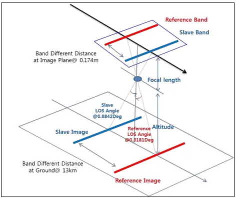
The features on ground are mapped to each band’s image plane with different displacement depending on the height and the CCD’s disposition. For example, when the ground projected distance between two bands is about 13km and 1.2km on ellipsoid, it shows the displacement in image plane in terms of ground distance depending on the target height as Figure 1. It shows that the displacement between bands for the same target varies depending on the height of target. In case of the location having about 1,000m height difference, registration errors between two bands will be caused by 20m and 2m, respectively. As shown in Figure 1, the registration errors become lager as position difference of CCDs on the effective focal plane getting larger.
Figure 1. Registration errors between two bands with different look angle
Terrain relief correction is to correct the local distortion between the reference and the slave band caused by the height variation on the surface and the CCD disposition. For this, we compensated geometrical distortion caused by parallax effect between two bands by establishing the each band’s precise sensor model utilizing the physical satellite characteristics and DEM data. It is important to establish the very accurate sensor model having the exactly combination of CCD lines in the focal plane projected on the ground distance among bands. To correct parallax effect in the slave band image, we only use the sensor model to reconstruct the slave image according to the reference geometry. Consequently, we remove the parallax effects to reconstruct the reference band’s geometry using the reference band’s camera model and height information. In order to establish each band’s sensor model, we need to get the exact position of CCD lines as the known as the sensor parameters. If we can be known the LOS (Line Of Sight) vector of the reference band in the specific region in the image plane at the specific time, we will reconstruct the LOS vector of the reference band within the target image using the sensor models. The procedure of the terrain relief correction is as follows. It partly include 5 steps: (1) to generate a several grids having the equivalent-space using target band image. (2) to calculate latitude and longitude in the geodetic coordinate system of the four corner points using the reference sensor models. (3) to extract height information from DEM data according with the four corner points of grids (4) to calculate the pixel location within the image coordinate system using the calculated latitude, longitude and height. (5) finally to replace resampled the calculated pixel values with the input pixels.
Figure 2. The Procedure of Terrain Relief Correction
The suggested algorithm is to apply the parallax effect of the reference band with the target bands. Therefore, the images applied with the suggested terrain relief correction are registered by all bands only using affine transformation.
3. EXPERIMENT
Experiment of our suggested algorithm is to evaluate the performance of the band registration. For this, we use the two images of the different spatial resolution, 1m and 4 m shown as Table 1.
Table 1. the related satellite images information
Reference band’s GSD 1m Target band’s GSD 4m Tilt angle -26.0°
We select the reference band as 4m resolution image and the target band as 1m. the configuration of all bands in focal plane is considering the ground distance as bellows Figure 3.
Figure 3. The Band Difference Distance corresponding on the configuration of CCD-lines.
International Archives of the Photogrammetry, Remote Sensing and Spatial Information Sciences, Volume XXXIX-B1, 2012 XXII ISPRS Congress, 25 August – 01 September 2012, Melbourne, Australia
These images have different looking angles which in combination the terrain relief cause to diverse geometric distortion. LOS angle of the reference bands is about 0.3181°
and the target’s LOS about 0.8842°. Band different distance between the reference and target at the image plane is about 0.174m. the altitude is about 685km and focal length about 9.022m.
We used SRTM DEM data as bellows. The resolution of DEM data is about 90m at the equator(CGIAR-SCI, 2008).
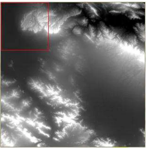
Figure 4. SRTM v4 DEM DATA (N34E049.demdata)
In order to evaluate the successfully results of each band registration; we used the 25-ground control points. For this, we distribute the control points within images as Figure 5. The height is ranging from 1753 meters in the mountains to 2411 meters.
Figure 5. the distribution of 25 GCPs in Google earth
In order to successfully analyse the result of band registration, the results of band registration using terrain relief correction are compared with the results of band matching without our suggested methods.
4. RESULTS
We experiment with 2 steps; (1) band registration results and (2) our suggested algorithm. Table 2 show the band registration results.
Table 2. Band Registration results
Col Errors Row Errors Col Errors Row Errors
M IN -3 -7.2264 -1.25 -3
M AX 6.25 8.5736 3.54 3
Range 9.25 15.8 4.79 6
AVG 1.2252 0.1056 0.4156 -0.0232
RM SEcol/Row 0.507390187 0.953820676 0.320552748 0.384387663 RM SETotal
Band Registration using Terrain relief correction Band Registration
1.080378954 0.500507682
We notify that our suggested algorithm is more successfully performed to match band images. In case of band registration, its registration ratio is about 1.08 RMSE pixels and but registration using terrain relief correction about 0.5 RMSE pixels[reference band resolution]. Therefore, as the results, we assume that the suggested terrain relief correction removes the pixels errors caused by height. And we analyse the effects of the height on the column and row as Figure 6 and Figure 7.
Figure 6. Column Errors depending on Height of band registration using terrain correction and without it
Figure 6 shows column errors of band registration without and with terrain relief correction depending on height. For correcting height relief, column errors are less than registration International Archives of the Photogrammetry, Remote Sensing and Spatial Information Sciences, Volume XXXIX-B1, 2012
XXII ISPRS Congress, 25 August – 01 September 2012, Melbourne, Australia
in the direction of column. We estimated a few points off trend lines are caused by the physical effects.
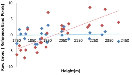
Figure 7. Row Errors depending on Height of band registration using terrain correction and without it
Figure 7 shows row errors of band registration without and with terrain relief correction depending on height. Unlike Figure 6, row errors are affected with the height. In case of band registration, row errors increase, and but in case of using terrain relief correction, row errors are steadly stable without depending on elevation.
5. CONCLUSION
High resolution optical satellites require taking image using a lager swath width comprised of multiple CCDs. The multiple CCDs may be placed at different position on the focal plane and then the different view direction is caused by the offset of the CCD lines in the scan direction. Even though the images of each band were taken from same ground area, they do not match together with simple affine transform due to parallax effect. These registration errors are higher by depending on the higher height variation. Therefore, in order to successfully register slave images to master image, we need to correct parallax effect caused by terrain relief. Our suggested algorithm successfully performs to correct terrain relief using rigorous sensor model having precise sensor parameters and ellipsoidal height information extracted from DEM data. As the results, we will be expected to correct the local distortion between bands caused by the CCD disposition and height effects.
REFRENCES
Arevalo, A. and Gonalez, J. 2006.A Comparison of Registration Techniques of Quickbird Satellite Images. ISPRS May 2006, Enschede, the Netherlands.
CGIAR-SCI, 2008. SRTM 90m Digital Elevation Data, August 19, 2008, http://srtm.csi.cgiar.org/.
Jacobsen, K. 2006. Calibration of Imaging Satellite Sensors. In: ISPRS Workshop: Topographic mapping from space (with
special emphasis on small satellites), ISPRS volume number: XXXVI-1/W41, Ankara, Turkey.
Kim. T and Dowman. I, 2005. Analysis of Sensor Model Accuracy on Estimating Exterior Orientation Parameters of Satellite Images, IEEE International Geoscience and Remote Sensing Symposium Proceedings, 25-29 July, 2005, Seoul, Korea
Kim. T, Kim. H, and Rhee. S, 2007.Investigation of Physical Sensor Models for Modelling SPOT 3 Orbits, The Photogrammetric Record, 22(119): 257-273.
International Archives of the Photogrammetry, Remote Sensing and Spatial Information Sciences, Volume XXXIX-B1, 2012 XXII ISPRS Congress, 25 August – 01 September 2012, Melbourne, Australia