THE EXTRACTION OF INDOOR BUILDING INFORMATION
FROM BIM TO OGC INDOORGML
Tee-Ann Teo a*, Sz-Cheng Yu b
a Dept. of Civil Engineering, National Chiao Tung University, Hsinchu, Taiwan 30010 - [email protected] b Dept. of Civil Engineering, National Chiao Tung University, Hsinchu, Taiwan 30010 - [email protected]
Commission V, WG V/8
KEY WORDS: Building Information Modeling (BIM), Indoor Information, IndoorGML, Industry Foundation Classes (IFC)
ABSTRACT:
Indoor Spatial Data Infrastructure (indoor-SDI) is an important SDI for geosptial analysis and location-based services. Building Information Model (BIM) has high degree of details in geometric and semantic information for building. This study proposed direct conversion schemes to extract indoor building information from BIM to OGC IndoorGML. The major steps of the research include (1) topological conversion from building model into indoor network model; and (2) generation of IndoorGML. The topological conversion is a major process of generating and mapping nodes and edges from IFC to indoorGML. Node represents every space (e.g. IfcSpace) and objects (e.g. IfcDoor) in the building while edge shows the relationships between nodes. According to the definition of IndoorGML, the topological model in the dual space is also represented as a set of nodes and edges. These definitions of IndoorGML are the same as in the indoor network. Therefore, we can extract the necessary data in the indoor network and easily convert them into IndoorGML based on IndoorGML Schema. The experiment utilized a real BIM model to examine the proposed method. The experimental results indicated that the 3D indoor model (i.e. IndoorGML model) can be automatically imported from IFC model by the proposed procedure. In addition, the geometric and attribute of building elements are completely and correctly converted from BIM to indoor-SDI.
1. INTRODUCTION
Building Information Modeling (BIM) emphasizes the building representation in 3D geometric and indoor semantic information. In order to achieve the data interoperability for indoor application, Open Geospatial Consortium (OGC) develops an Indoor Geography Markup Language (IndoorGML) (OGC, 2015a) that deals with indoor spatial information. Building Information Modeling (BIM) contains high geometrical details and riches in the attribute information. It could be a spatial data source for indoor Spatial Data Infrastructure (indoor-SDI). Therefore, the extraction of indoor building information from BIM to open standard is an important issue in indoor-SDI.
Industry Foundation Classes (IFC) is an open data format for openBIM. IFC data format is adopted in this study as most BIM model can be converted to IFC as an exchange data. The aim of this study is to propose a procedure to convert the BIM to OGC IndoorGML model through IFC (Industry Foundation Classes) model directly. Khan et al. (2014) described a transformation process to automatically generate IndoorGML model from CityGML (OGC, 2015b). First, BIM model needs to be converted to CityGML LoD4. Then, the CityGML LoD4 is further converted to IndoorGML. This process is an indirect method which converts BIM to OGC IndoorGML model through CityGML model. The building entities of IFC and CityGML are not equal. If we use the converted CityGML model to generate the IndoorGML model, it might lose some information. In order to prevent these situations, this study uses IFC directly as a dataset to generate indoor information for IndoorGML model.
Representing the geometry of the object was the main target in previous researches, which gained success in visualization but was limited for spatial analysis (Kim et al., 2013). In recent years, several spatial data models make efforts in representing 3D space. Some of them intend to describe the interior space of
buildings, such as IFC and CityGML LoD 4. IndoorGML plays a complement role of candidate standard to those existing standards for spatial analysis. Given the rising interest, more and more studies discuss integrating IndoorGML with other spatial data models, which are reviewed as follows.
Kim et al. (2013) developed a new semantic model called Indoor Spatial Data Model (ISDM) based on concepts of CityGML ADE and IndoorGML. ISDM supported indoor information for spatial analysis and location based services through topological information. In ISDM, CityGML ADE provided the basic conceptual framework including Core Indoor Module and Building Indoor Module. The former was used to describe 3D indoor space; while the latter was used to represent building elements. IndoorGML in here was used for dealing with topological information, for example, transferring indoor information to NRS for representing the relationship of objects in the space. By integrating the characteristics of CityGML ADE and IndoorGML, ISDM could represent both geometry and topology of indoor space and make spatial analysis possible.
Kim et al. (2014) proposed methods and guidelines for integration of CityGML and IndoorGML. First of all, featuring out the entities mapping relationship was the foundation of the integration. The correspondence of entities could be identified by code list, ontology in or control value. For example, Room in CityGML could be classified into room and passage according to the ontology in, then they would be mapped to GeneralSpace and TransitionSpace in IndoorGML Navigation Module, respectively. The second step was to automatically generate IndoorGML model from CityGML model. Following IndoorGML definitions, spatial information derived from CityGML was mapped to CellSpace or CellBoundary of the primal space, and topological information of NRG was mapped to State or Transition in the dual space. The topology model could easily explain the topological structure of indoor space. The International Archives of the Photogrammetry, Remote Sensing and Spatial Information Sciences, Volume XLII-4/W2, 2017
FOSS4G-Europe 2017 – Academic Track, 18–22 July 2017, Marne La Vallée, France
This contribution has been peer-reviewed.
However, it was insufficient for computing optimal route because the route was quite differed from the navigation route of ordinary pedestrians. For this reason, the solution by creating an extra layer was proposed. According to the definition of multi-layered representation in IndoorGML, the extra layer was used for navigation by splitting the original space into multiple instances to improve the route.
The objective of this research is to extract the indoor building information from BIM to indoorGML. The proposed method include (1) topological conversion from building model into indoor network model; and (2) generation of IndoorGML. The topological conversion is a major process of generating and mapping nodes and edges from IFC to indoorGML. In this step, we extract 3D indoor network model from IFC for IndoorGML conversion. An indoor network is a data model which is converted from IFC model automatically. It is mainly composed of nodes and edges. Node represents every space (e.g. IfcSpace) and objects (e.g. IfcDoor) in the building while edge shows the connection relationships between nodes. According to the definition of IndoorGML, the topological model in the dual space is also represented as a set of nodes and edges. These definitions of IndoorGML are the same as in the indoor network. Therefore, we can extract the necessary data in the indoor network and easily convert them into IndoorGML based on IndoorGML Schema.
2. METHODOLOGIES
The conversion of BIM/IFC to IndoorGML dual space model contain three major processes: data preprocessing, topological conversion, and modeling IndoorGML model. In data preprocessing, the coordinate system transformation is to transform the relative coordinate system of BIM to mapping frame in IndoorGML. The explanations of each step are stated below.
Figure 1. Workflow of the proposed scheme
2.1 Entities Analysis
IndoorGML is composed of two main modules including Core Module and Extension Module. On one hand, the data which are transformed from indoor network models in the primal space is mapped in the entities in Core Module. On the other hand, in the Navigation Module of IndoorGML (one of the Extension Module), feature types of building can be classified into space or boundary, and both of them also subdivide into navigable and non-navigable according to the function and usage. Base on the definition, Table 1 sorted the entity relationships of IFC and IndoorGML.
Table 1. Entity relationship between IFC and IndoorGML (modified from Kim et al., 2014)
Module:Core Module (dual space) Element type IndoorGML entities IFC entities
Elevator room,
NavigableSpace AnchorSpace IfcDoor ConnectionSpace IfcDoor GeneralSpace IfcSpace TransitionSpace IfcSpace NonNavigableSpace NonNavigableSpace IfcWall,
IfcWallStandardCase NavigableBoundary AnchorBoundary IfcDoor
ConnectionBoundary IfcDoor
In this process, we use indoor network model as the data source for IndoorGML conversion. Indoor network is a data model converted from BIM/IFC model. It is mainly composed of nodes and edges. Node represents every spaces and objects in the building, while edge stands for the relationships between nodes. According to the definition of IndoorGML, the topological model in the dual space is also represented as a set of nodes and edges. These definitions of IndoorGML are the same as in the indoor network. Therefore, users can extract the necessary data in indoor network and convert them to IndoorGML format based on IndoorGML Schema. In other words, the topological conversion from BIM/IFC to IndoorGML is the process of generating and mapping nodes and edges.
2.2.1 Node Generation
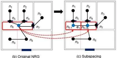
Node is the basic unit of the topological model in the dual space, which represents every cell space in the primal space in the indoor environment. According to the space property, methods for generating nodes can be different. For the simple and closed space or building objects, nodes can be generated by automatic calculation. It is a method to generate a node in the centroid by calculating the shape of the space or object (Kim et al., 2014). It can be used for rooms (IfcSpace), opening elements (IfcOpeningElement), or walls (IfcWallStandardCase). In contrast, for the complex and open space such as corridors (IfcCorridor) and stairs (IfcSpace), automatic calculation may cause some problems such as wall-pass or spider-net routes. In order to avoid these situations, manual digitization and subspacing (Figure 2) can be applied.
Figure 2. Subspacing method, (a) original NRG, (b) NRG after subspacing (IndoorGML, 2013)
2.2.2 Edge Generation
Edge is the connection of the topological model in the dual space, which represents the relationship between adjacent nodes. In order to generate edges, the connection between cells in the primal space must be checked (Kim et al., 2014). Edge The International Archives of the Photogrammetry, Remote Sensing and Spatial Information Sciences, Volume XLII-4/W2, 2017
FOSS4G-Europe 2017 – Academic Track, 18–22 July 2017, Marne La Vallée, France
This contribution has been peer-reviewed.
generation is an automatic process. Basing on the opening element, users identify rooms sharing the same one so that the corresponding nodes can be connected. For example, IfcRelSpaceBoundary defines the relationships between building elements and the space including physical and virtual (buildingSMART, 2007; Cho, 2014). Similarly, it can also be used for describing the connected spaces of the building element. Therefore, by extracting this entity, connection information can help confirm the linkage relationships between spaces and opening elements. Figure 3 shows the concept of IfcRelSpaceBoundary for physical boundary.
Figure 3. IfcRelSpaceBoundary: the case of physical space boundary (modified from buildingSMART, 2007)
2.3 Integrating IndoorGML Information
Integrating the generated nodes and edges is the last process to convert BIM/IFC information to IndoorGML dual space model. It is further separated into two steps: mapping information into IndoorGML and establishing the linkage between related node and edge. In IndoorGML, nodes and edges are represented as entities of State and Transition, respectively (Kim et al., 2014), enabling users to easily map the information by following the definition. Moreover, for the nodes and edges that are in linkage relationship, we directly map the connection attribute in the corresponding entities. As shown in Figure 4, node “ST0” and node “ST1” are connected by the edge “TR0_1”. Therefore, in State entity, the information of the connective edge is mapped onto the node; in Transition entity, the corresponding nodes are mapped onto both ends of the edge.
Figure 4. Concept of IndoorGML mapping
3. EXPERIMENTAL RESULTS
3.1 Test Data
The BIM model to evaluate the proposed method is Taipei Main Station, Taipei City (see Figure 4). This BIM model was modeled by this study based on 2D CAD graphs, 3D CAD models and field surveying. It contained seven floors on the ground and two basements. The model in both project mode and rendering mode is shown in Figure 4. In addition, it was noted that the building height was an inaccuracies of the model because our 2D graphs and 3D models were lacked of elevation and complete building height respectively. To solve this problem, we could only measure it by field measurement and using aerial images. The estimated height of the building was about 48 meters and be
average distributed to each floor. We used Autodesk Revit 2014 to build up this BIM model and convert to IFC 2x3 format.
Figure 4. BIM model
3.2 IFC to Indoor Network
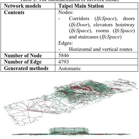
IFC is an open standard to exchange BIM model. This study used FME software to extract the indoor building entities of IFC for further processing. Once the indoor building entities were extracted, we developed a program to calculate the nodes, extract the edges, and connect the nodes and edges automatically. The attributes from IFC also attached on nodes and edges. Therefore, the indoor network is not only a geometrical network. It also contains attribute of indoor space. The generated network model and related information are shown in Figure 5 and Table 2, respectively.
Table 2. The summarization of network model Network models Taipei Main Station
Contents Nodes:
- Corridors (IfcSpace), doors (IfcDoor), elevators hoistway (IfcSpace), rooms (IfcSpace) and staircases (IfcSpace) Edges:
- Horizontal and vertical routes Number of Node 5846
Number of Edge 4793 Generated methods Automatic
Figure 5. Network model of Taipei Main Station
3.3 IFC to IndoorGML
In Taipei Main Station, building objects that were converted to nodes included doors and rooms that were corresponded with IfcDoor and IfcSpace in IFC entities, respectively. According to the function and usage, rooms were further divided into corridors, elevator rooms, general rooms, and staircases. All the nodes, corridors, doors and general rooms were used for generating horizontal routes of each floor, while elevator rooms and staircases were used for vertical routes. By converting the information of nodes and edges into XML Schema mentioned in Section 2.1, the Core Module of IndoorGML was generated. The statistics of information in conversion process is shown in Table The International Archives of the Photogrammetry, Remote Sensing and Spatial Information Sciences, Volume XLII-4/W2, 2017
FOSS4G-Europe 2017 – Academic Track, 18–22 July 2017, Marne La Vallée, France
This contribution has been peer-reviewed.
3. There is one row named “connection lost” which was used to record number of nodes and edges that failed connecting to their corresponding targets. As summarized in the table, it is concluded that network models generated by automation effectively connected all the nodes and edges.
Table 3. The statistics of information in IndoorGML conversion of Taipei Main Station
Corridor Corridor -Door
Room -Door
Stair All
Nodes 2532 1075 2195 44 5846
Edges 2521 645 1605 22 4793
Conversion times (s)
4.59 1.54 3.23 0.31 9.10
Connection lost 0 0 0 0 0
File size (MB) 1.97 0.62 1.41 0.02 3.85
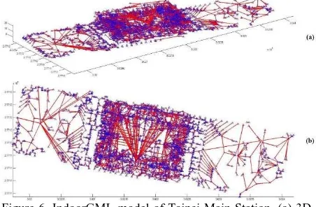
In order to visualize the generated indoorGML model, we used MATLAB to take the place of drawing model graphs. Figure 6 shows the whole model in IndoorGML. In Figure 6, blue triangles and red lines represent State and Transition in IndoorGML dual space model, respectively.
Figure 7. Edited IndoorGML models in different floors According to the result shown in Table 3 and Figure 6, the IndoorGML dual space model was successfully converted from BIM/IFC model, and all the linkage relationships between State and Transition also were mapped in the corresponding entities introduced in Section 2.3. However, irrational routes were the other problems of concern in IndoorGML model. For example, in broad spaces, some routes can be presented either in netlike (on the upper left of Figure 6(a)) or radial (in the middle of Figure 6(a)). Although either of the expressions can display the topological relationships of the model, the routes may be far away from ordinary pedestrians. To solve this problem, we edited the auto-generated routes with manually digitized routes in the
network model because the latter had the better interpretation in open or complex spaces. Figures 7(a) to 7(g) shows the horizontal network from ground to seventh floor. Figure 7(h) shows the vertical network automatically generated from stairs. The edited result shows the improved model in IndoorGML format, and it suggests more rational and regular routes in the middle part.
4. CONCLUSIONS AND FUTURE WORKS
In this study, we proposed a strategy to convert BIM/IFC model to IndoorGML model. The proposed method emphasized on BIM/IFC to IndoorGML for the spatial analysis and further applications of topological information. In IndoorGML conversion, all the nodes and edges were connected with their adjacent targets. By combining the results of manual digitization and automatic generation, IndoorGML dual space model efficiently avoided the occurrence of remissness and was closer to the real situation. As shown in the results of IndoorGML models, auto-generation of indoor network may occasionally result in irrational routes such as netlike or radial routes. To solve this problem, manual digitization may be a potential method to apply. Future works will focus on overcoming the problem of inappropriate routes by pedestrian constrain.
ACKNOWLEDGEMENTS
This research was partially supported by the Ministry of Interior and Ministry of Science and Technology of Taiwan.
REFERENCES
BuildingSMART, 2007. IFC2x Edition 3 Technical Corrigendum 1. Retrieved from http://www.buildingsmart-tech.org/ifc/IFC2x3/TC1/html/index.htm (last date accessed 2017/05/14).
BuildingSMART, 2014. Homepage of buildingSMART. Retrieved from http://www.buildingsmart.org/ (last date accessed 2017/05/14).
IndoorGML, 2013. Homepage of IndoorGML. Retrieved from http://indoorgml.net/ (last date accessed 2017/05/14).
Khan, A.A., Donaubauer, A. and Kolbe, T.H., 2014. A multi-step transformation process for automatically generating indoor routing graphs from existing semantic 3D building models. Proceedings of the 9th International 3DGeoInfo Conference, Dubai, UAE, 20 pages.
Kim, J.S., Yoo, S.J., and Li, K.J., 2014. Integrating IndoorGML and CityGML for Indoor Space. In D. Pfoser and K.J. Li (Eds.), W2GIS 2014, LNG&C, Springer-Verlag, Berlin, Germany, pp. 184-196.
Kim, Y.J., Kang, H.Y., and Lee. J., 2013. Development of Indoor Spatial Data Model Using CityGML ADE. International Archives of the Photogrammetry, Remote Sensing and Spatial Information Sciences, Volume XL-2/W2, pp. 41-45.
Open Geospatial Consortium, 2015a. OGC IndoorGML. Retrieved from http://www.opengeospatial.org/standards/indoorgml (last date accessed 2017/05/14).
Open Geospatial Consortium, 2015b. CityGML. Retrieved from http://www.opengeospatial.org/standards/citygml (last date accessed 2017/05/14).
Figure 6. IndoorGML model of Taipei Main Station, (a) 3D model, (b) plan view
The International Archives of the Photogrammetry, Remote Sensing and Spatial Information Sciences, Volume XLII-4/W2, 2017 FOSS4G-Europe 2017 – Academic Track, 18–22 July 2017, Marne La Vallée, France
This contribution has been peer-reviewed.