Juan Moreno García-Loygorri
Antonio Pérez-Yuste
César Briso · Marion Berbineau
Alain Pirovano · Jaizki Mendizábal (Eds.)
123
LNCS 10796
13th International Workshop
Nets4Cars/Nets4Trains/Nets4Aircraft 2018
Madrid, Spain, May 17–18, 2018, Proceedings
Lecture Notes in Computer Science
10796
Commenced Publication in 1973 Founding and Former Series Editors:
Gerhard Goos, Juris Hartmanis, and Jan van Leeuwen
Editorial Board
David Hutchison
Lancaster University, Lancaster, UK Takeo Kanade
Carnegie Mellon University, Pittsburgh, PA, USA Josef Kittler
University of Surrey, Guildford, UK Jon M. Kleinberg
Cornell University, Ithaca, NY, USA Friedemann Mattern
ETH Zurich, Zurich, Switzerland John C. Mitchell
Stanford University, Stanford, CA, USA Moni Naor
Weizmann Institute of Science, Rehovot, Israel C. Pandu Rangan
Indian Institute of Technology Madras, Chennai, India Bernhard Steffen
TU Dortmund University, Dortmund, Germany Demetri Terzopoulos
University of California, Los Angeles, CA, USA Doug Tygar
University of California, Berkeley, CA, USA Gerhard Weikum
Juan Moreno Garc
í
a-Loygorri
Antonio P
é
rez-Yuste
C
é
sar Briso
•Marion Berbineau
Alain Pirovano
•Jaizki Mendiz
á
bal (Eds.)
Communication Technologies
for Vehicles
13th International Workshop
Nets4Cars/Nets4Trains/Nets4Aircraft 2018
Madrid, Spain, May 17
–
18, 2018
Proceedings
Editors
Juan Moreno García-Loygorri Escuela Técnica Superior de Ingeniería
de Sistemas de Telecomunicacion Madrid
Spain
Antonio Pérez-Yuste
Escuela Técnica Superior de Ingeniería de Sistemas de Telecomunicacion Madrid
Spain César Briso
Escuela Técnica Superior de Ingeniería de Sistemas de Telecomunicacion
Ecole Nationale de l’Aviation Civile Toulouse Cedex 4
France
Jaizki Mendizábal
Ceit-IK4 Asociación Centro Tecnológico San Sebastián - Donostia
Spain
ISSN 0302-9743 ISSN 1611-3349 (electronic) Lecture Notes in Computer Science
ISBN 978-3-319-90370-5 ISBN 978-3-319-90371-2 (eBook) https://doi.org/10.1007/978-3-319-90371-2
Library of Congress Control Number: 2018940151
LNCS Sublibrary: SL5–Computer Communication Networks and Telecommunications ©Springer International Publishing AG, part of Springer Nature 2018
This work is subject to copyright. All rights are reserved by the Publisher, whether the whole or part of the material is concerned, specifically the rights of translation, reprinting, reuse of illustrations, recitation, broadcasting, reproduction on microfilms or in any other physical way, and transmission or information storage and retrieval, electronic adaptation, computer software, or by similar or dissimilar methodology now known or hereafter developed.
The use of general descriptive names, registered names, trademarks, service marks, etc. in this publication does not imply, even in the absence of a specific statement, that such names are exempt from the relevant protective laws and regulations and therefore free for general use.
The publisher, the authors and the editors are safe to assume that the advice and information in this book are believed to be true and accurate at the date of publication. Neither the publisher nor the authors or the editors give a warranty, express or implied, with respect to the material contained herein or for any errors or omissions that may have been made. The publisher remains neutral with regard to jurisdictional claims in published maps and institutional affiliations.
Printed on acid-free paper
This Springer imprint is published by the registered company Springer International Publishing AG part of Springer Nature
Preface
The Communications Technologies for Vehicles Workshop series provides an inter-national forum on the latest technologies and research in the field of intra- and inter-vehicle communications. It is organized annually to present original research results in all areas related to physical layer, communication protocols and standards, mobility and traffic models, experimental andfield operational testing, and performance analysis among others.
First launched by Tsutomu Tsuboi, Alexey Vinel, and Fei Liu in Saint Petersburg, Russia (2009), the Nets4Workshops series (Nets4Cars/Nets4Trains/Nets4Aircraft/Nets4 Spacecrafts) have been held in Newcastle upon Tyne, UK (2010), Oberpfaffenhofen, Germany (2011), Vilnius, Lithuania (2012), Villeneuve d’Ascq, France (2013), Offenburg, Germany (2014 Spring), Saint Petersburg, Russia (2014 Fall), Sousse, Tunisia (2015 Spring), Munich, Germany (2015 Fall), San Sebastian, Spain (2016 Spring), Halmstad, Sweden (2016 Fall), and Toulouse, France (2017 Spring).
These proceedings contain the papers presented at the 13th International Workshop on Communication Technologies for Vehicles Nets4Workshops series (Nets4Cars/ Nets4Trains/Nets4Aircraft/Nets4Spacecrafts 2018), which took place in Madrid, Spain, in May 2018, organized by the Universidad Politécnica de Madrid (Spain).
The call for papers resulted in 17 submissions. Each of them was assigned to the international Technical Program Committee to be reviewed at least by two independent reviewers. The co-chairs of the four Technical Program Committees (Nets4Cars, Nets4Trains, Nets4Spacecrafts, and Nets4Aircraft) selected 17 full papers for publica-tion in these proceedings and presentapublica-tion at the workshop,five of them for Nets4Cars, seven for Nets4Trains, andfive for Nets4Aircraft. In addition, two demonstration papers were also accepted and a keynote speech focused on Nets4Spacecrafts. The order of the papers presented in these proceedings was aligned with the workshop program.
The general co-chairs and the Technical Program Committee co-chairs extend a sincere“thank you”to all the authors who submitted the results of their recent research as well as to all the members of the hard-working comprehensive Technical Program Committee that worked on the reviews.
March 2018 Juan Moreno García-Loygorri
Organization
General Co-chairs
Antonio Pérez-Yuste Universidad Politécnica de Madrid, Spain Marion Berbineau IFSTTAR, France
César Briso Rodríguez Universidad Politécnica de Madrid, Spain Juan Moreno
García-Loygorri
Universidad Politécnica de Madrid, Spain
Alexey Vinel Halmstad University, Sweden
TPC Co-chairs (Nets4Trains)
Jaizki Mendizabal CEIT and Tecnun (University of Navarra), Spain Juan Moreno
Garcia-Loygorri
Metro de Madrid S.A./Universidad Politécnica de Madrid, Spain
TPC Co-chairs (Nets4Aircraft)
David Matolak University of South Carolina, USA Pedro Pintó Marín Hispasat, Spain
Alain Pirovano ENAC, France
César Briso Universidad Politécnica de Madrid, Spain Alexey Vinel Halmstad University, Sweden
TPC Co-chairs (Nets4Cars)
Antonio Pérez-Yuste Universidad Politécnica de Madrid, Spain Mohammed Kassab ENISO, University of Sousse, Tunisia
Steering Committee
Marion Berbineau IFSTTAR, France
César Briso Rodríguez Universidad Politécnica de Madrid, Spain Jaizki Mendizabal CEIT and Tecnun (University of Navarra), Spain Juan Moreno
García-Loygorri
Universidad Politécnica de Madrid, Spain
Antonio Pérez-Yuste Universidad Politécnica de Madrid, Spain Alain Pirovano ENAC, France
Technical Program Committee
F. JoséArqués Universidad Politécnica de Madrid, Spain Aitor Arriola Ikerlan, Spain
Marion Berbineau IFSTTAR, France HervéBonneville MERCE, France
César Briso Universidad Politécnica de Madrid, Spain César Calvo-Ramírez Universidad Politécnica de Madrid, Spain Ana González Plaza Universidad Politécnica de Madrid, Spain Cristophe Gransart IFSTTAR, France
Ke Guan Beijing Jiaotong University, China Danping He Beijing Jiaotong University, China Mohammed Kassab ENISO, University of Sousse, Tunisia Jaizki Mendizabal CEIT, Spain
Juan Moreno García-Loygorri
Universidad Politécnica de Madrid, Spain
Antonio Pérez-Yuste Universidad Politécnica de Madrid, Spain Joshua Puerta CEIT, Spain
JoséManuel Riera Universidad Politécnica de Madrid, Spain
Stephan Sand DLR, Germany
Mohammad Soliman DLR, Germany
Hosting Institution
Universidad Politécnica de Madrid, Spain
Organizing Committee
César Briso Rodríguez Universidad Politécnica de Madrid, Spain Juan Moreno
García-Loygorri
Universidad Politécnica de Madrid, Spain
Antonio Pérez-Yuste Universidad Politécnica de Madrid, Spain
Co-organizer and Sponsoring Institution
Contents
Nets4Aircrafts and UAV
3D Air-X UAV Communications: Challenges and Channel Modeling . . . 3 David W. Matolak
IP Mobility in Aeronautical Communications . . . 16 Alexandre Tran, Alain Pirovano, Nicolas Larrieu, Alain Brossard,
and Stéphane Pelleschi
Routing in Wireless Sensor Networks for Surveillance of Airport
Surface Area . . . 27 Juliette Garcia, Alain Pirovano, and Mickaël Royer
Reverberation Time in Vehicular Cabins . . . 39 Ana González-Plaza, César Briso, César Calvo-Ramírez,
and Juan Moreno García-Loygorri
A Deterministic Two-Ray Model for Wideband Air Ground
Channel Characterization . . . 44 Cesar Calvo-Ramirez, Cesar Briso, Ana Gonzalez-Plaza,
and Juan Moreno Garcia-Loygorri
Nets4Trains
Defining an Adaptable Communications System for All Railways . . . 53 Ben Allen, Benedikt Eschbach, Marion Berbineau,
and Michael Mikulandra
Survey of Environmental Effects in Railway Communications . . . 56 Nerea Fernandez, Saioa Arrizabalaga, Javier Añorga, Jon Goya,
Iñigo Adín, and Jaizki Mendizabal
LTE-Based Wireless Broadband Train to Ground Network Performance
in Metro Deployments . . . 68 Haibin Wu, Xiang Zhang, Lei Xie, Julian Andrade, Shupeng Xu,
and Xue Yang
Technologies Evaluation for Freight Train’s Wireless Backbone . . . 79 Francisco Parrilla, Marina Alonso, David Batista, Adrián Alberdi,
Characterization of a Wireless Train Backbone for TCMS . . . 92 Juan Moreno García-Loygorri, Iñaki Val, Aitor Arriola,
and César Briso
Narrowband Characterization of a Train-to-Train Wireless Link at 2.6 GHz
in Metro Environments . . . 100 Aitor Arriola, Iñaki Val, Juan Moreno García-Loygorri,
and César Briso
Evaluating TCMS Train-to-Ground Communication Performances Based
on the LTE Technology and Discreet Event Simulations . . . 110 Maha Bouaziz, Ying Yan, Mohamed Kassab, JoséSoler,
and Marion Berbineau
Nets4Cars
A Vehicle Recognition Method Based on Adaptive Segmentation . . . 125 Yusi Yang, Yan Lai, Guanli Zhang, and Lan Lin
Traffic Signal Recognition with a Priori Analysis of Signal Position . . . 137 Yingdong Yu, Yan Lai, Hui Wang, and Lan Lin
Standardizing IT Systems on Public Transport: An Eco-Driving Assistance
System Case Study . . . 149 Joshua Puerta, Alfonso Brazález, Angel Suescun, Olatz Iparraguirre,
and Unai Atutxa
Fading Characterization of 73 GHz Millimeter-Wave V2V Channel Based
on Real Measurements. . . 159 Hui Wang, Xuefeng Yin, Xuesong Cai, Haowen Wang, Ziming Yu,
and Juyul Lee
A Flexible TDMA Overlay Protocol for Vehicles Platooning . . . 169 Aqsa Aslam, Luis Almeida, and Frederico Santos
Abstract of Invited Talks
Demo for Channel Sounding in the Air-to-Ground Link. . . 183 Cesar Briso
Software Demonstration for Millimeter-Wave Railway Communications . . . . 184 Ke Guan
Author Index . . . 185
3D Air-X UAV Communications: Challenges
and Channel Modeling
David W. Matolak(&)
University of South Carolina, Columbia, SC 29208, USA [email protected]
Abstract. The use of unmanned aerial vehicles (UAVs) is growing rapidly, for an expanding variety of applications. These UAVs range in size from a few centimeters to the size of passenger jet aircraft, and willfly a large assortment of missions that take them from the stratosphere to residential neighborhoods. Control and communications must hence be extremely reliable. In this paper we summarize some key characteristics of UAV communications, describe funda-mentals and challenges for reliable UAV communications, some current efforts in the area, and provide a framework for analysis and modeling of a vital component in any UAV communication system: the air-ground channel. Fea-tures of this channel are discussed, with example references to the literature. Suggestions for future work in air-ground channel modeling are provided. The conference presentation of this work will include example results.
Keywords: Unmanned aircraft
Drone
Channel modeling
1 Introduction
The use of unmanned aerial vehicles (UAVs), also known as unmanned aircraft sys-tems (UAS) and by the popular term “drones,”has been growing rapidly. News on UAVs appears in the popular press daily, with applications also expanding, e.g., [1]. Work on, and use of, these vehicles and their operation and applications spans entities from international organizations such as the International Telecommunications Union (ITU) [2] to individual consumer hobbyists. If projections of the numbers of UAVs aloft in the worldwide airspace come true, thousands of UAVs will be in continuous operation in the skies above the United States alone within the next 10 years [3].
There are multiple ways to classify UAVs [4], and multiple organizations around the globe are preparing for their use in both controlled airspace [5,6] and uncontrolled or“loosely controlled”airspace [7]. The airspace definitions are generally defined by the International Civil Aviation Organization (ICAO) [8], and are functions of altitude, aircraft size and capabilities, proximity to populated areas, and sometimes local reg-ulations. Airspace definitions can be changed temporarily for reasons of safety or military purposes.
©Springer International Publishing AG, part of Springer Nature 2018
J. Moreno García-Loygorri et al. (Eds.): Nets4Cars 2018/Nets4Trains 2018/Nets4Aircraft 2018, LNCS 10796, pp. 3–15, 2018.
Operating UAVs requires communications, navigation, and surveillance (CNS), just as for piloted or“manned,”i.e., human-occupied aircraft1. Yet for UAVs, addi-tional requirements may be imposed. This is because UAVs can have missions that are dramatically different from those of piloted aircraft, and such missions can yield physical differences including UAVflight locations, kinematics (velocities and accel-erations, both linear and angular) and momentum,flight duration, and range. Examples include UAVsflying very near or within urban areas, forests, or indoors, UAVsflying at stratospheric altitudes over continental distances continuously over multiple days, as well as UAVsflying rapidly at extremely low altitudes generally considered too close to earth to be safe for human-occupiedflights. These differences affect the requirements of UAV CNS systems.
The growth of UAV applications and numbers will impose new demands for more reliable CNS systems for a larger number of aircraft. Safety of human life, then property, are the paramount concerns, but system efficiency and other considerations (e.g., cost) are also germane in CNS system design. New UAV CNS systems will need to be more reliable, adaptive, and rapid than present systems.
In this paper we focus on communications for UAVs. Section2 provides a brief overview of UAV communications and networking, comparing with other forms of communication systems such as those for terrestrial applications, and for conventional human-occupied aircraft. Some fundamentals and challenges are described, motivating study of the air-ground (AG) channel. This is followed by a short overview of some example recent work on UAV CNS systems. Since an accurate characterization is essential to the design of reliable UAV communication systems, in Sect.3we describe the AG channel and its characterization. Section4presents suggestions for future work on UAV communications, and Sect.5 concludes with a summary.
2 UAV Communications and Networking
The topic of UAV communications and networking is both broad and deep, hence our treatment is necessarily a summary one. Such aircraft could of course form networks of UAVs alone (sometimes called swarms) as well as networks of UAVs connected with piloted aircraft [9]. Most such networks ultimately connect to one or more ground stations (GS). For small UAVs the link may be to a single individual. Links through other platforms such as satellites, high-altitude platforms, and mobile earth stations on terrestrial vehicles (e.g., cars, trains) and boats are also possible, and many of these are planned for the future. Many of these types of links are also formed in military communication networks involving aircraft. These sorts of multi-platform aircraft
1Some organizations, e.g., ICAO, prefer to use the term“remotely piloted aircraft”(RPA) for UAVs, but this term could exclude UAVs whoseflights are“pre-programmed”and hence—if considered piloted at all—are piloted only by specifyingflight path in advance. Also, RPAs can carry human occupants. In this paper we use the terms UAV and piloted aircraft as two distinct classes, recognizing the imprecision of these designations.
.
connections are often designated air-X, and in some cases such connections may be established opportunistically [10].
The use of UAVs is being considered, and is taking place at present, for a large number, and growing variety, of applications. Small rotorcraft, whose maneuverability and hovering capabilities are attractive for some applications, are often used, butfixed wing UAVs are used as well. A partial list of applications includesfilming, police and public safety surveillance, industrial monitoring, scientific and environmental obser-vation, agriculture, package delivery, civil infrastructure inspection, and the augmen-tation of terrestrial networks by the addition of a“third dimension”(3D) composed of UAVs aloft. The cellular community has recently been increasing its attention on UAV communications for terrestrial network augmentation with LTE [11, 12]. So-called “smart community”applications are also envisioned [13,14].
Much prior work used for communications in terrestrial applications and for piloted aviation applications naturally pertains to UAV communications: the same layers of the communications protocol stack are used, but some differences arise. As with com-mercial piloted aircraft, UAVs can move at velocities larger than those of terrestrial vehicles. As aircraft altitude increases, the communication link range also generally increases. Traditional civil aviation is conservative for safety reasons, and for passenger aircraft, still uses analog voice communications at VHF for pilot to air traffic control. This is changing, but slowly. In order to improve UAV link performance, new tech-niques are being proposed. This includes physical layer techtech-niques such as multicarrier waveform designs [15, 16], and multiple access layer techniques [17], as well as techniques at the networking layer and above.
The performance of any communication technique depends strongly upon the channels over which signals travel. This is because in many cases the wireless channel is the most significant impediment to communications reliability, as it can be lossy, distorting, and temporally and spatially varying. Because of the importance of com-munication link reliability to safety, the air-ground (AG) channel for UAVs has seen renewed attention from researchers [18]. In the subsections that follow, we provide a summary of some of the fundamentals and challenges associated with UAV commu-nications, largely at the physical and data link layers, and then highlight some notable recent work on UAVs.
2.1 Fundamentals and Challenges
Two of thefirst things associated with UAVs are altitude and mobility. Although the altitude of UAVs (especially small ones) can be very low, one of the communications advantages of aircraft is their ability to move above local obstacles. This generally increases the probability of a line of sight (LOS) to any GS, and that reduces channel attenuation (path loss). In cellular-like deployments of UAVs, this can be a disad-vantage as well, as interference also propagates far in LOS conditions, and hence must be balanced against desired signal levels [19]. Very low-altitude flight makes some channel characteristics for the UAV similar to terrestrial channels, but such flights introduce other challenges, such as careful and accurate navigation.
reasons (e.g., mission requirements, winds). Fast moving aircraft can produce larger Doppler shifts that must be tracked by receivers. This may become significant for higher frequency bands that are being proposed: an example is the 5 GHz band that the ITU is considering for UAV use, where with small UAVs traveling up to 100 miles/hour (45 m/sec), Doppler shifts can reachfD=v/k= vf/c=45(5109)/3108= 745 Hz.
Herek is wavelength, f frequency, and c the speed of light. This Doppler shift2is approximately 5% of the current (15 kHz) subcarrier spacing used in LTE, and requires compensation and tracking. If the Doppler spreads are also appreciable, this could produce significant performance degradation, particularly in multicarrier systems, where the spreads induce inter-subcarrier interference.
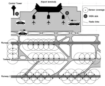
Doppler spreads constitute the range of Doppler shifts imposed upon transmitted signals, typically caused by multipath propagation—the multipath components (MPCs) travel longer distances than the LOS component, and arrive at the receiver at different spatial angles. Doppler spread values generally scale with the angular extent of scat-tering around the GS, since scatterers near UAVs are rare, except for low-altitude flights, or perhaps when a UAV isflying in a large swarm. Even in such low-altitude cases though, the UAV AG channel can be much more rapidly varying than terrestrial channels. Figure1illustrates these considerations for a near-airport setting.
Controlling UAV mobility, especially when there is more than a small number of aircraft, can be challenging, even if the UAVs are notflying in swarms. Many aircraft —piloted and UAVs—rely on the Global Positioning System (GPS) or other satellite navigation systems. If this is unavailable for some reason, navigation must be done by other means, using signals transmitted from known geographic locations, or inertial computations, or use of maps and sensors (e.g., radar altimeters). Controlling mobility becomes more difficult as altitude decreases, and must be more precise as UAVflights take place near built-up areas, vegetation, or terrain. Traditional air traffic management (ATM) techniques used for civil piloted aircraft will be insufficient for such cases; more will be said on this in the next subsection. Small UAVs must also contend with winds and weather, and depending upon frequency band and geometry, these could also impact communication performance, as they can affect UAV location and antenna orientation. Table1 provides a short list of some of the features distinguishing UAV from terrestrial communications.
2.2 Example Recent Work
As noted, a number of organizations are working on UAV deployments, regulations, and the communications and networking technologies required to safely and reliably operate UAVs. Here we highlight just a few visible efforts.
2Note that this Doppler shift is the maximum absolute value for a single platform (transmitter or receiver) in motion, which occurs when the platform is directly approaching or receding from the GS. When theflight path is not along this line,fDis multiplied bycos(h), wherehis the angle between
velocity vector and LOS line. If both platforms are in motion, the calculation naturally becomes more complicated.
.
The National Aeronautics and Space Administration (NASA) of the United States has several programs in UAV research. One is UAS in the National Airspace System (NAS) [20], depicted in Fig.2, and the other is UAS Traffic Management (UTM) [7], depicted in Fig.3. NASA is generally supporting the US Federal Aviation Adminis-tration (FAA); the FAA has designated several UAV test sites across the United States. As indicated in Figs.1 and 2, the two NASA programs have different objectives. The UAS in the NAS program is targeted at medium and larger size UAVs that would, at least for a portion of theirflight, share airspace with piloted aircraft. This program investigated AG channel models (more in the next section), surveillance techniques (often termed“detect and avoid”), and communications and networking requirements at the lower few layers of the communications protocol stack. Several standards were developed by the Radio Technical Commission for Aeronautics (RTCA) [21], and these standards made use of the NASA UAS in the NAS work. The latest work in this program is focusing on high-reliability air-satellite links.
In contrast, the NASA UTM program is aimed at smaller, low-altitude UAVs. This includes UAVsflying in populated areas, for such services as package delivery and law enforcement. A somewhat related effort is Uber’s Elevate program [22]. In this project, the company that pioneered the“crowd-source-taxi”service plans to extend this to an Fig. 1. Illustration of UAVs and piloted aircraft in near-airport environment, emphasizing altitude and mobility (adapted from NASA).
Table 1. Qualitative comparison of characteristics of terrestrial and UAV communications.
Characteristic Terrestrial (cellular) UAV
Velocities Typically small Potentially very large Probability of LOS Typically small Potentially large
Temporal availability Very long •Large for“loitering”fixed-wing aircraft •Very small for rotorcraft
Range Small-medium Potentially very large Mobility management Well established Ill-defined
air passenger service. Their plan is for vertical takeoff and landing aircraft that will initially ferry passengers from one tall building to another, in urban areas. If that proceeds successfully, Uber will extend to other flights within metropolitan areas. Theseflights will initially be“pre-programmed”and will have a licensed pilot on board as an emergency back-up measure.
The cellular industry has also initiated some research from individual companies [19, 23], and from the cellular industry organization Third Generation Partnership Project (3GPP) [24,25]. These efforts are aimed at using the cellular standard Long Term Evolution (LTE) for low-altitude UAV connections, and contain some interesting field trial results. This industry’s interests are primarily in enlarging their subscriber base. This has been done with the provision of cellular and internet service to airline
Fig. 2. NASA UAS in the NAS illustration [20].
passengers from companies such as GoGo [26] and SmartSky [27], which essentially employ terrestrial cellular base stations with directional antennas pointed to cover the hemisphere above.
Numerous other efforts, both from individual investigators, and small teams, have also appeared, and the literature is growing rapidly. We cannot be comprehensive here, but note only a few examples: [28,29,30]. Interested readers are encouraged to turn to the literature, e.g., [10,31].
3 Channel Modeling for UAVs
Study of the wireless channel for UAVs has grown in the past several years. This mostly pertains to the AG case, although air-satellite and air-air channels have also seen some attention. All these, and other air-X channels have remaining work to do as well. Here we focus on the AG channel.
As with other types of channels, the AG channel may be classified into categories such as LOS versus non-LOS (NLOS), and by altitude, frequency band, etc. From an engineering perspective, for links through the troposphere from the lower VHF band (>30 MHz) through the EHF band (few hundred GHz), the channel can be modeled as a linear time varying system, hence it is completely characterized by its impulse response (IR) h(s,t), or equivalently by the Fourier transform of the IR, the time-varying channel transfer function (TF) H(f,t). There is a rich literature on modeling channels in this way, so we do not cover fundamentals here. See [18,32,33,34].
3.1 AG Channel Model Framework
Figure4provides an illustration of the AG channel; worth pointing out is that from the perspective of the channel, the designation of “unmanned”or “piloted”is irrelevant. Note that the structure of the channel model embodied in Fig.4 is general, and can apply for example to small UAVs. In Fig.4 we identify five primary components (MPCs) that can exist between a GS and aircraft (and vice-versa, as the channel is reciprocal):
Fig. 4. Illustration offive primary components in the AG channel.
1. The line-of-sight (LOS) component is often, but not always present.
2. The surface component. This may be mostly specular, or, depending on surface roughness, may be substantially suppressed. Spherical earth divergence can also be accounted for (typically only significant at large link distances).
3. Lateral multipath components (MPCs). These emanate from large, electrically smooth objects such as buildings, or smooth hillslopes. Other large objects such as vehicles (land or watercraft, parked aircraft…) may also contribute, depending on the local setting.
4, 5. Diffuse and unresolvable MPCs can be components from rough surface scat-tering, which can be treated with component #2 (i.e., they have delay very close to that of the primary surface component), or can be from rough obstacle surface scattering, but associated with objects that generate lateral MPCs (#3), or might be components from obstacles very near the GS.
Components four and five can likely be represented as a single type, possibly differentiated according to their source (or according to delay).
Additional comments on these components are as follows:
1. The LOS component if present can be computed from the AG geometry, and from knowledge of the tropospheric refractivity profile. For the simplest level of model(s), at short range, refractivity can be assumed constant. Given link dis-tance, this component is deterministic, and can be computed via the free-space Friis transmission equation.
2. The surface component can be computed from a two-ray model. The curved-earth two-ray (CE2R) model is more accurate than the flat-earth 2R (FE2R) model, but for the simplest model level and short link ranges, the FE2R can be used [37]. The strength of this component must account for surface roughness (e.g., via Rayleigh criterion & Gaussian surface height distribution) and wave divergence (negligible for short ranges). Except for random surface variations, and any randomness (actually, uncertainty) in surface material parameters (permittivity e and conductivity r), as with the LOS component,
given geometry, this component is also deterministic.
3. For“known”settings where complete environment information is available, the lateral MPCs can be estimated from maps and geometry, essentially ray-tracing from GS to obstacle to aircraft (or from GS to ground to obstacle to aircraft) for the largest objects in the environment. A starting point for a “geometric-stochastic” AG model could employ the ITU-R recommendation P.1410 [36], which has an empirically based model for building distributions that accounts for overall building density and building heights. Such channel models would benefit by generalizing this ITU-R model to allow for buildings of different shape, multiple building façade orientations, large vehicles, etc. Thus, in general these lateral MPCs will be stochastic.
from portions of the aircraft itself, might also be“traced.”Weak MPCs at delay values not associated with components 1-3 can also be included. Aside from the approximately known delays of some of these MPCs, these components will also be stochastic.
In Table 2 we provide a list of some qualitative comparisons of AG channel characteristics between the terrestrial and UAV cases.
3.2 Modeling Considerations
For engineering purposes, models for path loss and narrowband amplitude fading are most essential. If signal bandwidths are large enough, delay dispersion models (i.e.,
h(s,t)orH(t,f)) are also required, and if mobility is large enough, Doppler models are also required. The simplest models, such as the single-path LOS model, which can employ the Friis transmission equation, are deterministic, but most often the AG channel is modeled as at least partly stochastic.
Example path loss models for the LOS AG channel (from the NASA UAS in NAS research) appear in [35,37,38]. These models take one of two forms: (i) the common log-distance form, or (ii) a quasi-deterministic form represented by a 2-ray model (CE2R or FE2R) plus random MPCs. Airframe shadowing—the attenuation caused by the air-craft itself by blockage of the LOS component—was also modeled in [39]. Small scale fading was modeled as Ricean, with K-factors approximately independent of distance, and at least 12 dB. All these models pertain to the aviation bands near 970 MHz and 5 GHz, but delays and numbers of MPCs should be applicable to frequency ranges beyond these values. Path loss models for urban settings are of great interest, but because of the difficulties of conducting measurement campaigns in these areas, only limited simulation models currently exist, e.g., [40], without experimental validation.
Because of the importance of accurate channel modeling to reliable UAV com-munications, research on the AG channel is expanding. Current topics of interest for smaller UAVs include low-altitude models [41, 42], vegetation effects [43] and accurate modeling of earth surface reflection [44], antenna pattern effects [45], and multiple-input/multiple-output (MIMO) [46]. Another topic is the estimation of sta-tionarity distance [35], the spatial extent over which channel statistics remain essen-tially constant.
Table 2. Qualitative comparison of channel characteristics relevant to terrestrial and UAV communications.
Characteristic Terrestrial (cellular) UAV
Path loss models Log-distance Friis, 2-ray, log-distance Narrowband small scale
Stationary distance Typically small Can be large if LOS present Doppler spreads Typically small Can be large if velocity large
4 Future Work
As alluded to throughout this paper, there is much remaining work in the area of UAV communications and networking at multiple layers of the communications protocol stack. Other topics such as mobility (air traffic) management, frequency band coordi-nation, and network resilience are also vital.
In terms of the AG channel, suggestions for future work are:
• estimation of stationarity distances as functions of altitude and locations; • quasi-deterministic adaptive/predictive models [47];
• urban AG path loss and delay dispersion models;
• future large-scale MIMO models, i.e., using entire aircrafts as arrays; • explicit models for air-X using cars, trains, and boats;
• millimeter wave band (mmWave) short range models.
5 Summary
In this paper we presented a review of communications and networking for unmanned aerial vehicles or UAVs. The rapidly growing use of these aircraft for multiple applications will require more reliable communication links. We described some fundamentals and challenges associated with communications for UAVs, and included a short review of some significant efforts to integrate UAVs into the worldwide air-space and more locally. A framework for air-ground channel modeling was also described, along with a very brief discussion of some practical modeling considera-tions. Several topics for future work were also presented.
Acknowledgment. The author would like to thank his colleagues Uwe Carsten-Fiebig, Nicolas Schneckenberger, Ismail Guvenc, Wahab Khawaja, Ruoyu Sun, and Hosseinali Jamal for col-laborations and discussions that have resulted in contributions to this work.
References
1. CNN Website. http://money.cnn.com/2018/02/15/technology/aerobotics-farm-app-drones/ index.html. Accessed 19 Feb 2018
2. International Telecommunications Union: Characteristics of unmanned aircraft systems and spectrum requirements to support their safe operation in non-segregated airspace. ITU-R M.2171, December 2009
3. US Department of Transportation: Unmanned aircraft system (UAS) service demand 2015–
2035: literature review and projections of future usage. Technical report, v.1.0, DOT-VNTSC-DoD-13-01, February 2014
5. Radio Technical Commission for Aeronautics (RTCA). www.rtca.org. Accessed 20 Feb 2018
6. Matolak, D.W.: Summary of NASA air-ground channel measurements and models. Appendix Q in Command and Control (C2) Data Link Minimum Operational Performance Standards (MOPS) (Terrestrial), Radio Technical Commission for Aeronautics (RTCA) Inc., 6 May 2016
7. National Aeronautics and Space Administration (NASA): Unmanned aircraft systems traffic management (UTM) program.https://www.utm.arc.nasa.gov/index.shtml. Accessed 22 Feb 2018
8. International Civil Aviation Organization (ICAO).https://www.icao.int/Pages/default.aspx. Accessed 19 Feb 2018
9. Bekmezci, I., Sahingoz, O.K., Temel, S.: Flying ad-hoc networks (FANETs): a survey. Ad Hoc Netw.11, 1254–1270 (2013)
10. Hayat, S., Yanmaz, E., Muzaffar, R.: Survey on unmanned aerial vehicle networks for civil applications: a communications viewpoint. IEEE Commun. Surv. Tutor.18(4), 2624–2661
(2016)
11. Lin, X., et al.: The sky is not the limit: LTE for unmanned aerial vehicles.https://arxiv.org/ abs/1707.07534. Accessed 27 Feb 2018
12. Van der Bergh, B., Chiumento, A., Pollin, S.: LTE in the sky: trading off propagation benefits with interference costs for aerial nodes. IEEE Commun. Mag.54(5), 44–50 (2016)
13. Menouar, H., Guvenc, I., Akkaya, K., Uluagac, A.S., Kari, A., Tuncer, A.: UAV-enabled intelligent transportation systems for the smart city: applications and challenges. IEEE Commun. Mag.55(3), 22–28 (2017)
14. Chandrasekharan, S., et al.: Designing and implementing future aerial communication networks. IEEE Commun. Mag.54(5), 26–34 (2016)
15. Kakar, J., Marojevic, V.: Waveform and spectrum management for unmanned aerial systems beyond 2025.https://arxiv.org/pdf/1708.01664.pdf. Accessed 27 Feb 2018
16. Jamal, H., Matolak, D.W.: FBMC and LDACS performance for future air to ground communication systems. IEEE Trans. Veh. Technol.66(6), 5043–5055 (2017)
17. Lyu, J., Zeng, Y., Zhang, R.: Cyclical multiple access in UAV-aided communications: a throughput-delay tradeoff. IEEE Wirel. Commun. Lett.5(6), 600–603 (2016)
18. Matolak, D.W.: Air-ground channels & models: comprehensive review and considerations for unmanned aircraft systems. In: IEEE Aerospace Conference, Big Sky, MT, 3–10 March
2012
19. Amorim, R., Nguyen, H., Mogensen, P., Kovacs, I.Z., Wigard, J., Sorensen, T.B.: Radio channel modeling for UAV communication over cellular networks. IEEE Wirel. Commun. Lett.6(4), 514–517 (2017)
20. National Aeronautics and Space Administration (NASA): UAS in the NAS.https://www. nasa.gov/centers/armstrong/programs_projects/UAS_in_the_NAS/index.html. Accessed 27 Feb 2018
21. Radio Technical Commission for Aeronautics: Command and control (C2) data link minimum operational performance standards (MOPS) (Terrestrial). DO-362, 22 September 2016
22. Uber, Inc.:https://www.uber.com/elevate.pdf. Accessed 27 Feb 2018
23. Qualcomm, Inc.: https://www.qualcomm.com/documents/lte-unmanned-aircraft-systems-trial-report. Accessed 27 Feb 2018
24. Third Generation Partnership Project (3GPP): Technical specification group radio access network; study on enhanced LTE support for aerial vehicles (Release 15). 3GPP TR 36.777, V15.0.0, December 2012
25. Third Generation Partnership Project (3GPP): TR 36.777, V15.0.0 Annex H: Field Trials Results on Mobility, December 2012
26. GoGo Business Aviation.https://business.gogoair.com/. Accessed 28 Feb 2018 27. SmartSky Networks.https://www.smartskynetworks.com/. Accessed 28 Feb 2018
28. Khawaja, W., Guvenc, I., Matolak, D.W.: UWB channel sounding and modeling for UAV air-to-ground propagation channels. In: IEEE Globecom, Washington, DC, 4–8 December
2016
29. Yanmaz, E., Kuschnic, R., Bettstetter, C.: Channel measurements over 802.11a-based UAV-to-ground links. In: Proceedings of IEEE Globecom, Wi-UAV Workshop, Houston, TX, December 2011
30. Takizawa, K., Ono, F., Suzuki, M., Tsuji, H., Miura, R.: Measurement on S-band radio propagation characteristics for unmanned aircraft system. In: Proceedings of EuCAP, The Hague, Netherlands, 6–11 April 2014
31. Khawaja, W., Guvenc, I., Matolak, D.W., Fiebig, U.-C., Schneckenberger, N.: A survey of air-to-ground propagation channel modeling for unmanned aerial vehicles, in review. IEEE Commun. Surv. Tutor. December 2017. http://export.arxiv.org/pdf/1801.01656. Accessed 28 Feb 2018
32. Parsons, J.D.: The Mobile Radio Propagation Channel, 2nd edn. Wiley, Chichester (2000) 33. Levis, C.A., Johnson, J.T., Texeira, F.L.: Radio Wave Propagation: Physics and
Applications. Wiley, Hoboken (2010)
34. Hlawatsch, F., Matz, G. (eds.): Wireless Communications Over Rapidly Time-Varying Channels. Academic Press, Burlington (2011)
35. Matolak, D.W., Sun, R.: Air-ground channel characterization for unmanned aircraft systems
—part I: methods, measurements, and results for over-water settings. IEEE Trans. Veh.
Technol.66(1), 26–44 (2017). (online 2016)
36. International Telecommunications Union: Propagation data and prediction methods required for the design of terrestrial broadband radio access systems operating in a frequency range from 3 to 60 GHz. Rec. ITU-R P.1410–5, February 2012
37. Sun, R., Matolak, D.W.: Air-ground channel characterization for unmanned aircraft systems
—part II: hilly & mountainous settings. IEEE Trans. Veh. Technol. 66(3), 1913 –1925
(2017). (online 2016)
38. Matolak, D.W., Sun, R.: Air-ground channel characterization for unmanned aircraft systems
—part III: the suburban and near-urban environments. IEEE Trans. Veh. Technol.66(8), 6607–6618 (2017). (online 2016)
39. Matolak, D.W., Sun, R., Rayess, W.: Air-ground channel characterization for unmanned aircraft systems—part IV: airframe shadowing. IEEE Trans. Veh. Technol. 66(9), 7643
–
7652 (2017). (online July 2017)
40. Al-Hourani, A., Kandeepan, S., Jamalipour, A.: Modeling air-to-ground path loss for low altitude platforms in urban environments. In: Proceedings of Globecom, Austin, TX, 8–12
December 2014
41. Simunek, M., Perez-Fontan, F., Pechac, P.: The UAV low elevation propagation channel in urban areas: statistical analysis and time series generator. IEEE Trans. Antennas Prop.61(7), 3850–3858 (2013)
42. Cai, X., Gonzalez-Plaza, A., Alonso, D., Zhang, L., Briso Rodriguez, C., Yuste, A.P., Yin, X.: Low altitude UAV propagation channel modeling. In: Proceedings of EuCAP, Paris, France, April 2017
43. Kvicera, M., Perez-Fontan, F., Israel, J., Pechac, P.: Modeling scattering from tree canopies for UAV Scenarios. In: Proceedings of EuCAP, Davos, Switzerland, 10–14 April 2016
44. Jost, T., et al.: Ground reflection for low elevations at L- and K-band. In: Proceedings of EuCAP, Davos, Switzerland, 10–14 April 2016
45. Arias, M., et al.: Statistical analysis of the radiation pattern of an antenna mounted on an aircraft. In: Proceedings of EuCAP, Davos, Switzerland, 10–14 April 2016
46. Willink, T.J., Squires, C.C., Colman, G.W.K., Muccio, M.T.: Measurement and character-ization of low-altitude air-to-ground MIMO channels. IEEE Trans. Veh. Tech.65(4), 2637–
2648 (2016)
47. Matolak, D.W., Jamal, H., Sun, R.: Spatial and frequency correlations in two-ray SIMO channels. In: IEEE ICC, Paris, France, 21–25 May 2017
IP Mobility in Aeronautical Communications
Alexandre Tran1,2, Alain Pirovano1(&), Nicolas Larrieu1, Alain Brossard2, and Stéphane Pelleschi2
1
Abstract. In the sake of modernization, aviation stakeholders decided that the future aviation network infrastructure, in particular for air-ground communica-tion systems, will move towards IP based networks. It has been referred to in the International Civil Aviation Organization as Aeronautical Telecommunication Network/Internet Protocol Suite. Due to the heterogeneous communication environment, it is necessary to support handover between different access technologies and access networks. In this article, wefirst define the very specific aeronautical communication environment. Our main contribution is a perfor-mance assessment of the most deployed network protocols capable of managing IP mobility within the aeronautical environment. We focus our analysis on the Mobile IPv6 protocol and implementation issues of a representative aeronautical network in Omnet++.
Keywords: IP mobility
Air ground communications
MIPv6
1 Introduction
The current aeronautical communication infrastructure for Air Traffic Management
(ATM) has to evolve in order to respond to an endless increase in air traffic and to support more stringent data link communications. In this way, aviation stakeholders gathered in several groups such as International Civil Aviation Organization (ICAO), European Organization for Civil Aviation Equipment (EUROCAE), Radio Technical Commission for Aeronautics (RTCA) and Airlines Electronic Engineering Committee (AEEC), are working on a future IP-based Aeronautical Telecommunication Network (ATN/IP). Its goal is to interconnect all the aeronautical subnetworks with the IPv6 protocol.
The aeronautical environment is different from other communication domains (e.g. personal wireless communication in 4G networks or vehicular communications). The two main key problems are the global mobility and the safety-related data which have very stringent quality of services (QoS) requirements. Whereas some solutions have already been proposed in [1], no solution has been taken on yet by the aviation industry. To handle the node mobility in IPv6, the Internet Engineering Task Force (IETF) has developed Mobile IPv6 (MIPv6) [2]. It allows a seamless communication between
©Springer International Publishing AG, part of Springer Nature 2018
J. Moreno García-Loygorri et al. (Eds.): Nets4Cars 2018/Nets4Trains 2018/Nets4Aircraft 2018, LNCS 10796, pp. 16–26, 2018.
a mobile node and its correspondent node via a Home Agent (HA). In this article, we investigate MIPv6 for an aeronautical scenario through the xMIPv6 model of the INET framework [3].
The remainder of the paper is organized as follows: Sect.2provides an overview of the aeronautical communications environment and its evolution towards IP based net-works. Section3highlights the need of managing the node mobility under different IP networks and presents some dedicated protocols, with their strengths and flaws. In Sect.4, we explain our simulation model for MIPv6 in a context of an aeronautical environment. We then analyze thefirst results and conclude with several suggestions for our simulation model and the IP mobility management in an aeronautical environment.
2 Aeronautical Air Ground Communications and Data Link
2.1 From Analog Voice to Data Link
Thefirst radio transmitter has been invented and tested by AT&T (American Telephone & Telegraph) in 1917, allowing for the first time voice communications between ground personnel and pilots. But, it was only in 1935 that airborne radios were con-sidered reliable and efficient enough to be widely deployed on existing aircraft. These air–ground communication means were proposed in order to increase air safety. From
these years, the very high frequency (VHF) band was mainly used for radiotelephony services between pilots and controllers. It has been further augmented with Satellite Communication (SATCOM) since the early 1990s. Hence, voice communications are possible even in oceanic areas where direct communications with VHF ground stations cannot be deployed regarding their range.
Nevertheless, considering the increasing number of aircraft in airspace, the lack of resources makes it necessary to foresee new solutions in order to avoid congestion. Data link (or digital data link) came up as the promising solution. Data link indeed provides the ability to transmit short and relatively simple digital messages between aircraft and ground stations via communication systems. In July 1978, the engineering department at Aeronautical Radio Incorporated (ARINC) introduced afirst data link means known as Aircraft Communications Addressing and Reporting System (ACARS). And during the
1980s, air traffic control (ATC) authorities promoted the use of ACARS between
controllers and pilots to improve the safety and efficiency of air traffic management. At the beginning of the 1980s, the International Civil Aviation Organization (ICAO) cre-ated a special committee known as Future Air Navigation System (FANS), where Boeing and then Airbus developed their products, known as FANS-1/A (Fig.1).
According to ICAO, four categories of communications are defined in aeronautical
telecommunications. Air Traffic Service Communications (ATSCs) and Aeronautical
Operational Control (AOC) Communications that are considered as safety related, and Airline Administration Communications (AACs) and Aeronautical Passenger Commu-nications (APCs) that group non-safety-related. Critical commuCommu-nications follow specific international rules defined by ICAO (for example, only some dedicated frequency band can be used) and are based on dedicated systems. These latter must meet very stringent QoS requirements mainly based on transaction time, continuity, availability and integrity. In this paper, our focus will be on critical services (ATSC and AOC).
Airbus and Boeing worked on afirst set of applications using the available tech-nologies for ground data communications focusing on oceanic and remote air-spaces with no radar coverage and poor high frequency (HF) voice communications. These applications thus addressed communication and surveillance needs for these
air-spaces. In parallel of the deployment of FANS-1/A, ICAO working groups continued
to develop standards for a new aeronautical dedicated network and a set of applications:
ATN (Aeronautical Telecommunication Network). In addition to ground–ground
applications, ATN also defines air–ground data link applications, similar to those of
FANS 1/A with some modifications and enhancements released in FANS-2/B. Besides,
ATN defines a global internetwork architecture. As such, it relies on different“real”
subnetworks, allowing interconnections between ATN routers. ATN defines a stack of Open Systems Interconnection (OSI) standardized protocols from the network layer up to the application layer. ICAO working groups also developed standards for the under-lying air–ground subnetworks: in the VHF and HF bands, and also through satellite.
More specifically, several technical choices or protocol stacks were proposed in the VHF band and are called VDL (VHF data link) mode 2 to 4. Thus, considering aero-nautical data link communications, in each successive generation, we found a set of application services (FANS), which uses an upper layer architecture based on lower layer architectures and radio systems (HF, VHF, SATCOM, etc.).
2.2 Future Trends
The aviation industry has identified the need to develop new data communication
protocols and services to meet the safety and performance requirements of aviation for the year 2020 and beyond. Besides, the aviation industry desires a modern, off-the-shelf, efficient, and robust network infrastructure common to both ATS and AOC safety services. Commercial IP has been identified to be the successor in the long term of the ATN/OSI network infrastructure. It will be referred as Aeronautical Telecommunica-tion Network/Internet Protocol Suite (ATN/IPS), based on IPv6. Indeed, the Internet
Protocol IPv6 is a widespread telecommunications standard in the industry that is maintained and extended by the IETF. It will favor the interconnection between aeronautical domains that have already begun to migrate to IPv6, like for instance ground networks. Also, IPv6 should support a world-wide deployment with enough address space. It will be implemented on both aircraft and ground infrastructure. It is expected to use multiple line-of-sight and beyond-line-of-sight subnetworks such as Inmarsat SwiftBroadband, Iridium Certus, AeroMACS, future SATCOM and L Band Digital Aviation Communication System (LDACS) systems, and VDL Mode 2.
ATN/IPS should benefit for all the actors. Greater communications are expected for airlines compared to ACARS and ATN/OSI, while avionic suppliers and airframe manufacturers will be capable to provide more bandwidth and capabilities by using
future data link technologies. The Fig.2 shows how the ATN/IPS network should be
used in the future.
3 IP Mobility
The need of being always connected to the Internet has significantly arisen since the last decade. Internet mobility has thus become an attractive research area over the years. Several solutions have been proposed to provide a seamless communication for an end user while on the move and changing his access network to the Internet. The process of switching onto different networks is called handover. The handover process is either horizontal or vertical, depending on whether it switches to the same network technology or a different one. A handover is efficient if the user does not perceive any interruption. The main difficulty is related to the fact that application sessions are identified with an IP address, so changing network access and thus IP address may result in application sessions being broken. Therefore, a handover mechanism that keeps the IP address will be transparent to the application layer.
Fig. 2. ATN/IPS implementation (from [4])
3.1 Mobility Main Principles and MIPv6 Protocol
Several solutions based on different layers can deal with the mobility in IP networks [1]. The more adapted solution to the aeronautical environment according to [1] is based on the network layer. Indeed, providing a solution above the network layer is not suited for a deployment in an aeronautical environment as it should be implemented on all the existing end systems. Besides, considering the aircraft as a mobile network, it makes more sense to manage the mobility issue at the network layer to avoid doing it for each running application. More details on other possibilities to handle the mobility in IP networks are presented in [1].
In the context of IPv6, the IETF has developed an extension to deal with the mobile nodes (MNs) in the network layer which is Mobile IPv6 (MIPv6) [2]. It provides an efficient and scalable mechanism to handle the node mobility in IP networks. Indeed, it allows mobile nodes to move and change their point of attachment without changing their IP address. Therefore, this mechanism is transparent to the upper layers and allows sessions continuity during a handover.
To do so, MIPv6 uses 2 IP addresses for each mobile node: a Home Address
(HoA) and a Care-of-Address (CoA). The first one identifies the node in its home
network and the second one allows to locate the node when it moves to a foreign network. The association of the 2 addresses is realized by an entity in the home network called the Home Agent (HA). Each time a MN attaches to a foreign network, it performs a binding association between its new CoA and its HoA by sending a Binding Update (BU) message to its Home Agent, which replies with a Binding Acknowl-edgement (BA) message. The HA then creates a bi-directional tunnel to forward traffic to the new location of the MN. A correspondent node (CN) communicates with the mobile node by using its HoA. Therefore, when a MN performs a handover to a new IP network, it remains transparent for its CNs.
This mechanism allows session continuity as all packets coming from CNs are captured by the Home Agent and then forwarded to MNs. However, it introduces a triangular routing because packets sent by the mobile node are forwarded by standard IP routes. To solve this issue, MIPv6 allows MNs to perform route optimization (RO) with their CNs. Route Optimization is carried out after a binding association. MN creates a secure bi-directional tunnel with its CNs so that packets are exchanged directly through this tunnel.
3.2 MIPv6 Enhancements
Whereas MIPv6 can provide session continuity during a handover phase, its mecha-nism is not well adapted in specific environments such as in aviation, or for some specific applications which require very constraint requirements. For instance, very long links have a direct impact on the handover delay and thus introduce a long period during which the mobile node is unreachable. In the following, some enhancements to MIPv6 are described in order to mitigate these issues.
HMIPv6 (Hierarchical MIPv6). HMIPv6 is introduced in [5] as an extension to MIPv6 and IPv6 Neighbor Discovery protocol (NDP). It helps reducing the signaling traffic during the handover phase for local mobility case thanks to a new entity called
the mobility anchor point (MAP). It works as a local HA for a MN. HMIPv6 separates the global network into different MAP domains, each one controlled by one or several
MAPs (see Fig.3). A MAP domain is different from a network domain. HMIPv6
introduces 2 addresses to manage the local mobility of a node: the regional care-of-address (RCoA) and the local care-of-care-of-address (LCoA). Thefirst one (RCoA) is used to realize the binding with the HA and the CN, if the route optimization procedure is triggered. MN obtains a new RCoA whenever it moves to another MAP domain and at-taches to a new MAP. Meanwhile, the second one (LCoA) is used as a binding with the RCoA in the MAP domain. This process allows the MAP to forward packets destined to a MN in its current location through the tunnel created between the RCoA and the LCoA. Besides, HMIPv6 makes the local mobility in a MAP domain transparent to the HA and the CN as the RCoA is not updated.
In consequence, HMIPv6 is more suitable for local mobility but presents some drawbacks in dealing with global mobility because MNs need to get 2 different IP addresses instead of only 1 with MIPv6.
FMIPv6 (Fast Handovers for MIPv6). FMIPv6, described in [6, 7] as a further enhancement to MIPv6, is a protocol that helps reducing the handover latency and the packet loss during a handover in MIPv6. FMIPv6 makes it possible by introducing a fast binding between MN’s previous access router (PAR) and MN’s next access router
(NAR). This tunnel is created before the binding with the HA. To do so, during the discovery phase, all the access routers must share information about their network
pre-fix so that MN can configure the new CoA accordingly. With this tunnel, data may be tunneled to the new access router even during the handover phase.
By introducing some complexity at the network level, FMIPv6 is more effective than MIPv6 during a handover as it allows to mitigate the negative effects such as handover latency and packet loss.
PMIPv6 (Proxy MIPv6). PMIPv6 [8] is a network-based mobility management. Un-like the previous protocols which are host-based approaches, the node mobility is
Fig. 3. Mobility management in HMIPv6
handled by access routers in the network. Its main interest is to reduce drastically the amount of signaling for the mobile node as it is no more involved in the process. Like HMIPv6, PMIPv6 provides mobility support within a domain called a PMIP domain. As long as the MN moves within the domain, the network has to track the location of MN, which keeps its IP address.
PMIPv6 introduces 2 new entities to manage the node mobility: the mobile access gateway (MAG) and the local mobility anchor (LMA). The MAG realizes the mobility-related signaling on behalf of the MN using its access links. It is responsible for detecting the movement of the nodes in the domain and for executing binding registration with the corresponding LMA. The LMA manages the routes for all mobile nodes in the domain. More information about the whole process are developed in [7,8,9].
In consequence, whereas similar to HMIPv6, PMIPv6 seems to be more appealing because it does not involve the MN in the process, and hence helps to reduce signaling traffic seen by the MN.
4 MIPv6 Performances Assessment in an Aeronautical
Context
During a flight, an aircraft will be covered successively and/or simultaneously by several air-ground subnetworks belonging to different administrative domains (AN-SPs and AC(AN-SPs) depending on its location.
In the current aviation network, an aircraft has a unique identifier (its ICAO address) by which it is reachable at any times. But moving towards different IP net-works, the aircraft must obtain an IP address corresponding to the air-ground subnet-work in use in order to maintain its reachability. Consequently, an IP mobility mechanism is required to maintain the ongoing sessions with the aircraft whenever it changes its point of attachment to the air-ground network. Session continuity must be carefully taken into consideration during the process. Indeed, it should not break the ongoing sessions while performing the handover. However, a session in a TCP/IP stack is broken as soon as the IP address is changed.
As afirst step of our research work, we decided to perform an evaluation of MIPv6 in a ATN/IPS representative network that will serve as a reference for our future proposal. Indeed, the aeronautical network infrastructure is not like a common ground network equipped with 4G, due to its limited air-ground link capacity coupled with very demanding requirements of ATS applications running on top of that. Therefore, metrics such as packet loss, handover delay, and signaling traffic must be carefully investigated.
A previous work has already been carried out in [10] to evaluate MIPv6 for
ATN/IPS. It highlights the fact that handover delay can be very long in particular scenarios.
Our simulation environment is based on Omnet++ [11], a discrete event simulator adapted for wireless communication and its IPv6 framework INET. Omnet++ is based on a modular architecture, thus make it simple to use existing modules and to develop
our own ones. The INET framework provides a xMIPv6 module which simulates the standard MIPv6 protocol described in [2]. For now, the xMIPv6 module was tested in a simple scenario.
4.1 Simulation Scenario, Parameters and Hypothesis
Links Modeling and MIPv6 Module. As we do not intend to perform an analysis on link technologies, we have implemented a simple wireless NIC (Network Interface Controller) on each node and router. The wireless NIC uses the well-known CSMA (Carrier Sense Multiple Access) protocol at the MAC (Medium Access Control) layer as in some existing air-ground systems like VDL mode 2, and an ideal physical channel free of errors (bit error, collision…). Hence, base stations have been omitted as the
mobile nodes communicate directly with routers equipped with a wireless NIC. In doing so, it allows us to focus only on network layer mechanisms. Besides, movement detection at the network layer is performed when MNs receive an Router
Advertise-ment (RA) announcing a new network prefix. The RFC 6275 recommends to set the
RA periodicity between 30 ms and 70 ms. This value seems very low in our context. As it is a source of signaling traffic, the value has been increased up to 300 ms. A further analysis on the impact of this parameter will be investigated. Besides, route
optimization has been removed from the MIPv6 module because ATS traffic may not
be forwarded by other non-certified providers.
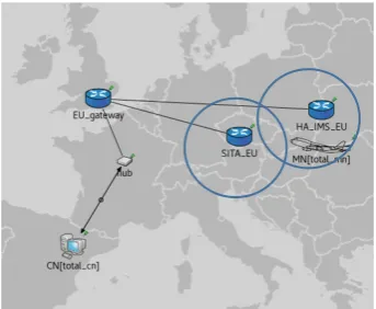
Ground Network. For a first step in our simulation, a simple handover between 2 access routers has been tested out, with one representing the HA for the mobile node, as shown in Fig.4. It’s a realistic scenario if we consider a continental scenario like in
Europe where connectivity to the ground network is provided by two Aeronautical Communication Service Providers (ACSPs): Rockwell Collins IMS (formerly ARINC) and SITA. Meanwhile, delay between those routers are modeled based on the
guar-anteed maximum delay between the 2 ACSPs [10]. For ATS services, the
communi-cation end point is an ATSU (Air Traffic Services Unit), which depends on the location
Fig. 4. Simulation scenario
of the aircraft. For now, the application layer integrates a PING application which sends ICMP (Internet Control Message Protocol) messages periodically.
Scenario. We consider one aircraft during its en-route phase at a cruise speed of 220 mps. It isfirst covered by IMS ground stations which is its HA andflies to a region covered only by SITA ones. The overlapping area, corresponding to the area where the aircraft has an access to both IMS and SITA, is about 50 km long.
As the IdealRadioMedium module is used to simulate the wireless medium, there is no link mechanism to associate the aircraft with only one access router on a dedicated channel. Therefore, when the aircraft goes through the overlapping area, it will receive
both network prefixes of IMS and SITA. The MIPv6 module running on the aircraft
will thus try to attach to both access networks successively as it will continue to receive RAs even after performing a binding with its new CoA. This phenomenon is known as the ping pong effect. A handover manager is therefore necessary to avoid this effect.
Handover Manager at L2. We thus decide to integrate a handover manager at the layer 2. It is an intermediate layer between the link layer and the network layer. Its role is tofilter incoming packets at the network layer of aircraft. Itsfiltering is based on a predefined priority list of ground stations. When it receives a beacon from a ground station, it checks whether this ground station has a greater priority than the current ground station in use. While this is a static and simple mechanism, it can be easily adapted in the future to a more dynamical decision process by modifying the priority list accordingly. To implement our handover algorithm, layer 2 beacons using MAC addresses have been added. They are sent every 300 ms by each access router with their respective MAC address and their ground station ID. RA messages of the MIPv6 module cannot be used for this purpose because our handover manager is run under the network layer, thus it does not manipulate IP addresses. Another more complex solution has been standardized in IEEE 802.21 [12], referred as Media Independent
Handover (MIH) to manage efficiently the handover between different wired and
wireless networks. Unfortunately, it is not yet developed for Omnet++ and is not our primary concern, that is why another approach has been taken.
4.2 Results and Analysis
In order to validate our proposal, several simulations have been run using MIPv6 mechanism on one side, and MIPv6 coupled with our handover manager on another side.
Figure5shows packets received by the aircraft at the link layer. By inspecting the size of packets, we deduce their type, thus helping us to determine the impact of our system on MIPv6.
Before a handover occurs, the aircraft only sees its HA, thus all the PING packets it receives come from the HA. Figure5 illustrates the same behavior in both cases (for t < 224 s), therefore our handover mechanism does not impact this phase. It only induced an additional signaling traffic coming from router beacons.
When the aircraft enters the overlapping area, it will have the choice between the 2 access routers. In the ideal case, leftfigure in Fig.5, between 220 s and 430 s, the aircraft receives some PING packets from the SITA ground station, highlighting the
ping pong effect. Those packets are longer (140 bytes instead of 100 bytes) than those sending by the HA because of the additional header corresponding to the tunneling mechanism. Whereas using our handover mechanism, rightfigure in Fig.5, the aircraft only receives PING packets of size 140 bytes, thus coming from the SITA station. In-deed, as soon as the aircraft detects the SITA ground station, it creates the binding and maintains it because SITA ground station gets a greater priority, as expected.
More interesting is the number of packet loss at the application layer in both case shown in Fig.6. With our handover manager, although there are still some lost packets, the number of loss is significantly reduced when the aircraft is covered by the 2 access networks (between 220 s and 430 s).
These first results validate our handover mechanism proposal. While being very elementary, it allows us to handle IP mobility effectively with MIPv6. Nevertheless, the long handover delay mentioned in [10] and the number of messages exchanged during the handover by the aircraft may prevent from meeting the stringent requirements for
performance of the ATS traffic. From the IP solutions introduced earlier, PMIPv6
seems to be a good candidate to overcome these issues as the signaling traffic on the air-ground link will be significantly lower.
Fig. 5. Packets received by the aircraft in an ideal case on the left, and with our manager on the right
Fig. 6. Packet loss in both scenarios