LinkSPath: A Novel Hybrid Restoration Scheme in
High Speed Optical Network
Satria Utama Istikmal Erna Sri Sugesti
PT Telekomunikasi Indonesia, Tbk. Telkom University Telkom University
Telkom Wilayah Bengkulu
Abstract—In optical network survivability, link-based and subpath-based restorations have been discussed in many papers as survivability methods for optical wavelength division multiplexing (WDM) network. One of the problem in both restoration methods occurs when network resources are unavailable. In such condition, the traffic is dropped and the source node is requested to retransmit the packages. This paper proposes LinkSPath, a hybrid scheme to increase the performance of network survivability by integrating both link- based and subpath-based restoration schemes. The scheme provides a redundancy for each other when one is not succeed based and subpath-based are first calculated. Alternative lightpaths are determined using Dijkstra algorithm. The NSFNET modelwas utilized. The simulation showed that the LinkSPath scheme has average restoration time which complies with ANSI standard and would not jeopardize communication. It also showed that LinkSPath has improved the individual performance of forming methods, Link-Based and Subpath- Based, in the number of restorations with recovery time smaller than retransmission.
Keywords—Optical networks; Survivability; Hybrid restoration; Link-based; Subpath-based; WDM networks
I. INTRODUCTION
Broadband services today require outstanding performance of the broadband networks to carry huge traffic and, at the same time, to detect an interruption due to network element failures and to survive from that critical condition. In a Wavelength Division Multiplexing (WDM) network with a 100 Gbps data rate (or even nearly 50Tbps [1]), the impact on the link or node failure is exacerbated by the extremely-high volume of traffic. An interruption means a huge revenue loss. Thus, optical link survivability has animperative role in the failure handling in high-speed optical networks and WDM networks require well-performance survivability.
In [2] the optical network restoration is categorized into three types: link, path and subpath restoration. One of the problem of all those restorations is that a connection would be dropped because of unavailable network resources [2].
In [3] protection switching time is maximum time for shared path protection, while the minimum one is for shared link
protection. In the other hand, the average blocking probability performs the minimum for shared path protection and maximum for shared link protection. To reduce the risk of traffic blocking, we consider to provide two different backup alternate paths by two restoration methods in one hybrid scheme. This integration could provide a backup for each other if the network resource is unavailable. However, the hybrid scheme must ensure a small recovery time as well, compared to retransmissionor path-based restoration as conventional method.
In this paper, a hybrid scheme of link-based and subpath- based restoration is proposed. This scheme first calculates alternative routes by link-based restoration and subpath restoration, and then determines the primary and secondary backup. So that if a link failure occurs, the primary backup will be used. When this route is not available, then the secondary backup takes the role. It is assumed that network model is all- optical network, therefore no wavelength conversions is required. Moreover, there is no failures occur at the same time.
Restoration was chosen because of higher efficiency of resources utilization compared to protection [4]. Proactive restoration scheme has a faster recovery time than reactive restoration, where the backup path of a link has been determined [2]. Moreover, the reactive restoration may not be100% success [5].
This paper is divided into six sections. In Section II the concept of network survivability, specifically restoration, and related works on optical network restoration are presented. Section III new concept named LinkSPath or link-based and subpath-based hybrid proactive restoration scheme are proposed. This section is compared to the basic concept, algorithm, switching signaling procedure, recovery time calculations, primary backup selection and path restoration calculation. Section IV contains the experiment scenarios, Section V includes simulation results and a discussion. Section VI concludes the result analysis and some proposed future works.
II. RESTORATION CONCEPT AND RELATED WORKS
A. Network Restoration Concept
(link-destination) → CD (connection-destination). The term of
connection-source, link-source, link-destination and
connection-destination refer to [6]. The cross sign between LS
and LD represents a link failure, hence that link becomes unavailable and the traffic must be detoured to CD.
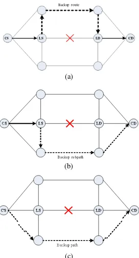
Refering to [7], link restoration involvesthe source node and destination node of the connection struggling with unidentified failure. It is only the adjacent nodes of the failed link participating in the reestablishment of the disrupted calls. The connection setup process between affected nodes is carried on through signaling messages traversing the backup route. For subpath restoration, the restoration algorithm tries to identify a route between the predecessor node before the failure and the destination node of each active lightpath of the link with failure [7].The path restoration scheme indentifies an alternative route from the source node until the destination node of the call. In this scheme, the wavelength continuity is not required.
B. Related Works
The research development in terms of network survivability is growing rapidly, as well asthe demand for easy-and- comparison between protection and restoration [8] was conducted as well as a survey of all researches [1], [3].
Backup route
CS LS LD CD
(a)
(b)
(c)
Figure. 1. Restoration types: (a) Link; (b) Subpath; (c) Path
Partial Path Protection (PPP [9]) is a hybrid scheme of path and link protection. It is a segment-based, failure dependent, centralized, dynamic, proactive, ILP-based protection strategy [7]. Each link failure of primary path is protected by an end-to- end protection path. PPP provides end-to-end protection based on local failure and local solution.
Survivability requires resources to handle failures. Allocation of resources can be classified into primary and backup lightpaths [10]. Moreover, allocation can also be processed by the link-based or path-based [11].
The researches have been step done for various goals. The minimum cost assignment of capacity on the edges and nodes of a network has been identified in which given demands can be even complied in case of either the failure of an edge or a node in the network [12]. In [10] blocking probability for the primary and backup lightpaths are measured and compared to both method results. The research has also been carried on to compare path-protection / restoration and link-protection / restoration [7]. Due to that fact, the path-protection providing significant capacity savings over link protection, and shared protection including significant savings over dedicated protection can be determined.
III. PROPOSED METHOD
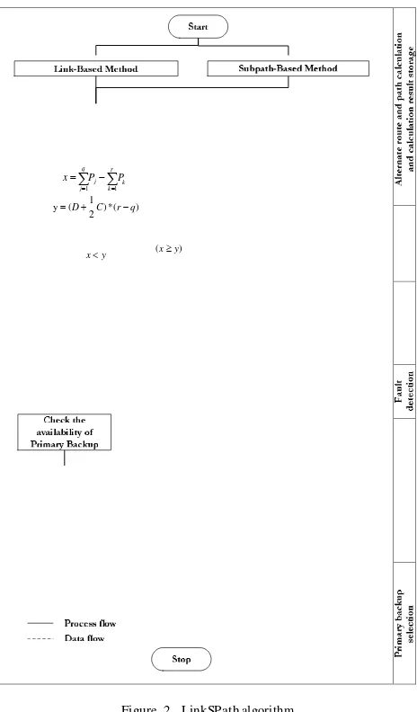
The proposed Link-Based and Subpath-Based Hybrid Proactive Restoration (LinkSPath) scheme is formed by two common restoration methods, the link-based and subpath- based methods, as seen in Fig.2. Both restoration schemes use Dijkstra algorithm [13] in calculating shortest route (of link-based) and shortest subpath(of subpath-based) and are simultaneously worked on. Combining two methods in a hybrid scheme aims to provide two different alternative routes and to reduce the risk of traffic blocking. The term
“proactive” means that the alternative routes and subpath are previously calculated. LinkSPath also calculates recover y time for both alternative route and subpath. The calculation results of these two methods are compared to and stored in a buffer as two options with different priority. If a link failure occurs, the connection will be rerouted to the previousl y calculated backup route or subpath.
LinkSPath applies a selection process to choose a pre- calculated backup route with the smallest recover y time and tag it as primary backupand secondary backup for the other one. If the primary backup is unavailable, the secondar y backup willthen take the role. In worst case, the second backup route or path might be unavailable as well, due to another link failure or node device failures. In this condition the traffic would be dropped and retransmission request
Rec
Rec
q r
x Pj Pk j 1 k 1 y (D 1 C ) * (r q )
2
x y ( x y)
Figure. 2. LinkSPath algorithm
Instead of utilizing bandwidth as “link weight”, LinkSPath uses physical length of the optical fiber that connects two adjacent nodes. This information determines the durationof restoration-switching. The distance of signaling message traversing in optical fiber is proper for recovery time.
B. Restoration -Switching Procedure
Since the alternative route and path are pre-calculated, the recovery time depends on solely failure detection to the end of restoration-switching process. Failure detection process is in flow chart in Fig.2, while the switching procedure for both link-based and subpath-based showed in Fig.3[6]. Flow chart in Fig.3 is part of LinkSPath algorithm in Fig.2.
The failed link is connected to link-source and link- destination. In link-based restoration these two nodes are involved in setting up the new connection. Signaling messages traverse throughout this alternative route. In subpath-based switching procedure, there are three nodes involving: link-
Figure. 3. Restoration-switching procedure. This is part of LikSPath algorithm in Fig.2
The connection-destination node receives fail-link message from link-destination and setup message from link- source. It also sends confirm message to indicate that it is ready for new connection.
C. Recovery Time Calculations
The recovery time calculation is based on the restoration- switching procedure as explained in Section III.B. All delay components are calculated from failure detection to traffic switching to new route or path. Most of assumptions in [3] are applied in this paper. Parameters such as tranmission rate, OXC configuration time, etc, uses the same assumptions with [3]. However, there are three different assumptions in this paper compared to [3] in recovery time calculation:
1. Transmission time for control message (setup message transmit time
t
s and confirm message transmit timet
c )is calculated to obtain an accurate calculation result.2. Since the link distance of each node in Fig.5is hundreds to thousands of kilometers, the propagation delay would rather be counted based on its physical length of each link, than using typical values.
3. Backup resource-availability checking time A in link- source (Eq.3). This parameter is a characteristic of LinkSPath, where switch duration A could be pcp or
pcp pcs for primary or secondary backup, respectively.
Eq.1 and Eq.2 show the link-based recovery time T LB and
subpath-based recovery time T SB calculation.
TRec
F t p td toxc ts t p t p td tc Asource, link-destination and connection-destination. LB ld (1)
p A shows availability checking timeand is assumed as 0.1 ms. Moreover,
t
p represents the total node processing time of allnodes on the backup route while
t
d deals with the total transmission delay in the backup route.In addition,t
oxc comesto the total optical cross-connects configuration time in the Figure. 4. Retransmissionand subpath switching signalling [6]
backup route,
t
s is the setup message transmit time in Link- Thedistance ( d ) unit of backup route or subpath is in kilometers (km) and can be obtained from Dijkstra running Sourceandt
c performs the confirm message transmit time in results.Link-Destination. Furthermore,
t
ls remains the confirm D. Primary Backup Selectionmessage processing time in Link-Source,
t
cd is the setup LinkSPath integrates both link-based and path-based by comparing the restoration time, selecting the shortest one and message processing time in Connection-Destination andt
ld isthe setup message processing time in Link-Destination. It is assumed that all nodes are identical and the processing delays ( td , t , t ) in each node equal to 0.11 ms. Referring to
state the route as primary backup,while the other as secondary backup. Eq.7 is the comparing step and is the requirement when determines link-based route as primary backup.
TRec
TRec (7)ld cd
p p
LB SB
[3], OXCs are assumed as identical and configurations time Substitute Eq.4 and Eq.5 to Eq.7 and Eq.8 is obtained
t
OXC equals to 10 ms and fail detection time F equals to 10Furthermore, the primary backup restoration time is stated confirm message transmit time, s and t , are gained with
as LinkSPath restoration time or T . Eq. 8 is used in
message length of n and nc divided by the transmission rate simulation as “primary backup selection” step with number of
R . All message length and transmission rate are deemed 2,000 bit and 1,000 bit/ms.Hence, the Eq. 1 and Eq. 2 can be simplified as Eq. 4 and Eq. 5.These equations refer to [3] with modification on orientation change to number of hops rather than nodes. The q and r are number of hops of link-based and subpath-based alternative routes, respectively.
q
n n
hops in switching signaling as variable. This simplified form of inequality would reduce calculation steps, save energy resource and calculation time.
restoration-switching process for both path-based restoration and retransmission. This does not mean both methods are run at the same time. Both methods are explained in one picture in
T SB F A 2 P 2rt t (r 1) s c
k 1 R R order to make the comparison easier. The drawing and
The propagation delay is calculated based on the length of the backup route or path and light speed assumption in vacuum of 2.99792458108 m/s or 299,792.458 km/s and the
Retransmission process refers to [6].The retransmission time
T is written in Eq.9 and simplified as Eq.10.
p i p
i
n n 1 n m m 1 m 1
refractive index is acquired from a factory product T F
P
D f t cs s
P
D
C ret j j p i i ispecification data 1.47 for G655 optical fiber. With these parameters, light speed in optical fiber can be found as
j 1 j 1 R
ST EP-1 m m 1
R i1 i 1 i1
ST EP-2 (9)
203.94044761048 km/ms. Thus, the sum of the propagation t cd nc
Pi
D t csdelay P of i th link from link-source is shown as follows. R i1 i1
n d d
S TEP -3
m n n
f ns nc (10)
milliseconds (6) Tret F 2
Pi
Pj m(C 2D) nD C R P
m
Figure. 5. NSFNET network model, 16 nodes and 22 bidirectional links
LinkSPath is effective if Eq.11 and Eq.12 are satisfied.
LB
Failed links
Figure. 7. Number of link-based and subpath-based restoration of each link
Tret TRec
seen in Fig.5. Each node has node number as node assignment. Miranda et al [13] performed an experiment with this
NSFNETnetwork in a very close to real life situation, so the Failed link
result provided was more realistic.For calculations, all assumptions are presented in Sec.III.C.
The experiment used MATLAB for searching shortest path by applying Dijkstra algorithm. MATLAB was also used to simulate link fails and calculate restoration time for link- based, subpath-based and retransmission.
Figure. 8. Average LinkSPath recovery time for each link failure. For comparison, the red line represents the average LinkSPath recovery time of all
restorations (72.27 ms).
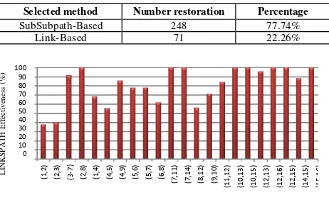
TABLE I. METHOD UTILIZATI ON AS PRI MARY BACKUP
V. SIMULATION RESULTS & DISCUSSION
Each link in network model is observed to find the number of source-destination pair that have shortest (primary) paths pass through it. Fig.6 shows this information for each link with a 319 total number of path.
LinkSpath selects smallest restoration time upon two choices: link-based or subpath-basedusing Eq.8. Fig.7 shows the number of link-based and subpath-based taken by LinkSpath from simulation for each failed link. For instance, Link (8,12) or link between node Champaign and Pittsburgh in Fig.5. From 32 paths pass through it, 18 paths are restored by subpath-based and 14 paths by link-based. In other hand,
there are 14 paths that would provide shortest restoration time besideslink-based or subpath-based.
The maximum and minimum restoration timesare 122.40 ms and 23.36 ms, respectively.The average restoration time for all restorations is 72.27 ms(red line).Moreover, Fig. 8shows the averagerecovery time of all restorations for each failed link. Eq.4 and Eq.5 were used to calculate each restoration time. The highest average recovery time is 104.47 ms for link (9,10), while the lowest is 23.36ms for link (12,16).
T T ret Re LBc Number of restorations Percentage Fig.9 shows LinkSPath effectiveness, which is defined as:
LinkSPath Retransmission
Effectiveness = 100%
LinkSPath
The ∑LinkSPath is number of all possible LinkSPath restoration when a link fails and ∑Retransmission is number of retransmissions which have smaller restoration time than LinkSPath’s. There were 65 retransmissions which have shortest restoration time out of 319 total restorations. This resulted 79.62% overall LinkSPath effectiveness.
The link (8,12) has the most primary paths with 32 paths. Sothat, the link (8,12) is the most critical link in NSFNET. A failure of this link may cause largest impact in the network, specifically capacity.
Small retransmission time is the opportunity to achieve better restoration time if retransmissions had taken. However, since retransmisson is not part of LinkSPath, the effectiveness was reduced to less than 100%. The effectiveness in other network topology with higher degree of nodes, may be higher
as well. A high degree node provides more alternative routes, so that it may increase the number of fast restorations.
Although Table I shows a large difference of link-based and subpath-based methods utilization,it indicates that both methods provideshortest alternative restorations and act as backup one another. However, both alternative routes need to be evaluated. If both are completely different routes with no similar links, then they are fully backups to each other. All the restoration times are under ANSI standard 200 ms of 2nd Restoration Target Range [15] and it may not disrupt the connection [16]. Nevertheless, the connection interuption due to restoration process and transmission delay via alternative route shoud be considered in calculating total interruption time.
Accordingto Table II, Table III and Table IV, LinkSPath shows a better performance than link-based and subpath-based individual performance. This is due to the primary backup selection process in Sect.III.D that selected all the smallest restoration times, so that all the larger one were not picked as primary backups.
TABLE II. RETRANSMISSION TO LINK-BASED RESTORATION RATI O
TABLE III. RETRANSMISSION TO SUBPATH-BASED RESTORATI ON RATIO
TABLE IV. RETRANSMISSION TO LINKSPATH RATIO
VI. CONCLUSION AND FUTURE WORK
LinkSPath combines advantages of common link-based and subpath-based methods and comply the ANSI Standard for the restoration time. Both methods provide their own alternative paths as redundant and offer them as the two options functioning to select the smallest restoration times. LinkSPath improves link-based and subpath-based individual performance on restoration time. There were retransmissions with smaller restoration time compared to that of LinkSPath. These retransmissions have reduced LinkSPath effectiveness.
For future work, the LinkSPath can be combined with physical impairment aware system to obtain a more-accurate primary backup selection. However, this may lead to increasing complexity.
REFERENCES
[1]. H. Saini, A. K. Garg, Protection and Restoration Schemes in Optical Networks: A Comprehensive Survey, International Journal of Microwaves Applications, Volume 2 No 1, January-February 2013 [2]. M. Ilyas, H. T. Mouftah, The Handbook of Optical Communication
Networks, ISBN 0-8493-1333-3, CRC Press LLC, 2003
[3]. H. K. Singh, S. Aggarwal, S. Singh, B. Mohapatra, R. K. Nagaria, and S. Tiwari, Performance Comparison of Protection Strategies in WDM Mesh Networks, Journal of Telecommunication and Information Technology, 2010
[4]. P. Arijs, B. Van Caenegem, P. Demeester, P. Lagasse, W. Van Parys, P. Achten, Design of Ring and Meshed Based WDM Transport Networks, Optical Networks Magazine, SPIE/Baltzer Science Publishers, July 2000 [5]. G. Mohan, C.S.R Murthy, Lightpath Restoration in WDM Optical
Networks, IEEE Network, IEEE, November/December 2000
[6]. S. Ramamurthy, L. Sahasrabuddhe, Survivable WDM Mesh Networks, Journal OfLightwave Technology, VOL. 21, NO. 4, IEEE, 2003 [7]. R. C. de Freitas, N. F. Aragão, L. B. Costa, R. C. L. Silva, D. A. R.
Chaves, H. A. Pereira, C. J. A. Bastos-Filho and J. F. Martins-Filho, On the Performance Analysis of Different Link to Path Restoration Schemes for All-Optical Networks, XXX SimpósioBrasileiro De
Telecomunicações - SBrT’12, 13-16 de Setembro de 2012, Brasília, DF
[8]. J. P.Vasseur, M. Pickavet, P. Demeester, Network Recovery – Protection and Restoration of Optical, SONET-SDH, IP and MPLS, ISBN: 0-12- 715051-x, Morgan Kauffman Publishers, 2004
[9]. H. Wang, E. Modiano, E. Médard, Partial Path Protection for WDM Networks:End-to-End Recovery Using Local FailureInformation, IEEE
ISCC’02, pp. 719–725
[10]. S. Rani , A. K. Sharmab, P. Singh, Resource Allocation Strategies For Survivability In WDM Optical Networks, Optical Fiber Technology 13
(2007) 202–208, Elsevier Inc, 2006
[11]. G. Maier, A. Pattavina, S. De Patre, M. Martinelli, Optical Network Survivability: Protection Techniques in WDM Layer, Photonic Network Communications, Kluwer Academic Publisher, 2002
[12]. M. GrÖtschel, S. Orlowski, Local And Global Restoration Of Node And Link Failures In Telecommunication Net works, Thesis,
FachbereichMathematik der TU Berlin,
StudiengangWirtschaftsmathematik, February 2003
[13]. E.W. Dijkstra. A note on two problems in connexion with
graphs,NumerischeMathematik, 1:269–271, 1959
[14]. A.M. L. Miranda, F.O. Lima, H.R.O. Rocha,N.Vijaykumar, C.R.L. Francês, M. E. V. Segatto, J. C. W. A. Costa, Wavelength assignment using a hybrid evolutionary computation to reduce cross-phase modulation, Journal of Microwaves, Optoelectronics and Electromagnetic Applications vol.13 no.1, 2014
[15]. ANSI Standard T1.TR.68-2001: Enhanced Network Survivability Performance
[16]. J. Schallenberg, “Is 50ms Restoration Necessary?”, proceedings of the
![Figure. 4. Retransmissionand subpath switching signalling [6]](https://thumb-ap.123doks.com/thumbv2/123dok/4029898.1973318/4.612.316.551.54.221/figure-retransmissionand-subpath-switching-signalling.webp)