EXTRACTING RAIL TRACK GEOMETRY FROM STATIC TERRESTRIAL LASER
SCANS FOR MONITORING PURPOSES
A. Soni a *, S. Robson a, B. Gleeson b a
Dept. of Civil, Environmental & Geomatic Engineering, University College London, Gower Street, London, WC1E 6BT, UK - ([email protected], [email protected])
b
Network Rail, James Forbes House, 27 Great Suffolk Street, London, SE1 0NS, UK – [email protected]
Commission V, WG V/4
KEY WORDS: terrestrial laser scanning (TLS), static, deformation monitoring, rail track, geometry, extraction
ABSTRACT:
This paper presents the capabilities of detecting relevant geometry of railway track for monitoring purposes from static terrestrial laser scanning (TLS) systems at platform level. The quality of the scans from a phased based scanner (Scanner A) and a hybrid time-of-flight scanner (Scanner B) are compared by fitting different sections of the track profile to its matching standardised rail model. The various sections of track investigated are able to fit to the model with an RMS of less than 3mm. Both scanners show that once obvious noise and artefacts have been removed from the data, the most confident fit of the point cloud to the model is the section closest to the scanner position. The results of the fit highlight the potential to use this method as a bespoke track monitoring tool during major redevelopment projects where traditional methods, such as robotic total stations, results in missed information, for example due to passing trains or knocked prisms and must account for offset target locations to compute track parameters.
* Corresponding author
1. INTRODUCTION
During the construction, demolition or upgrade of any infrastructure project it is essential to protect and cause as little disruption as possible to all retained assets within the zone of impact. Literature shows how deformation monitoring methods can be applied through various geodetic and geotechnical technologies depending on several factors including the required monitoring accuracy and frequency. The design of a monitoring network, whether it is absolute or relative, is crucial to ensure the accuracy requirements are met (Cooper, 1987). Logistical factors such as accessibility to the feature and availability of power supplies etc. must also be taken into consideration when developing a monitoring scheme.
1.1 Traditional Monitoring Approaches
Total stations observing to retro-reflective glass prism targets are a well-known and established method for a variety of deformation monitoring applications (Cosser et al, 2003; Psimoulis and Stiros, 2007), particularly of monitoring railway infrastructure during construction and redevelopment projects (Berberan et al, 2007; Tse and Luk, 2011). Whilst this method is highly accurate, precise and repeatable, the monitoring system is an intrusive and expensive solution and there is a reliance on prism movements physically correlating with rail movements. Therefore there is a drive to find alternative approaches for railway monitoring, particularly those without target requirements.
1.2 Related Work
Terrestrial laser scanning (TLS) has become a widely used tool for monitoring infrastructure due its ability to remotely capture
large volumes of 3D data at high speed and with reasonable accuracy offering the ability to measure features, as opposed to targets, in a variety of remote environments such as landslides, dams and locks etc. (Lindenbergh and Pfeifer, 2005; Monserrat and Crosetto, 2008; Abellán et al, 2009). Monitoring of railway infrastructure, such as newly constructed tunnels, using TLS has also introduced the development of tunnel deformation analysis techniques (van Goslgia et al, 2006; Nuttens et al, 2014).
Literature of using TLS for monitoring of rail track is focused towards effective methods of automatically extracting track geometry from the point cloud to produce 3D trajectories and models using static and mobile laser scanning (MLS) systems. Liu et al (2011) present a method of track extraction from static TLS data to obtain an accurate 3D track reference with the potential to identify deformations from subsequent TLS surveys. By producing a 3D mesh of a laboratory railway track, they apply an automatic edge detection algorithm to produce a track trajectory line. Ground truth points on the track observed using a total station support an accuracy estimate of the extracted track. Results show a mean difference of 2mm in the horizontal and 3mm in the vertical between the ground truth and the 3D mesh. Even though an automatic extraction method for track trajectory has been developed, it is unclear if the 3D model output conforms to the physical form of the track, and what distribution of ground truth has been used to validate the method. MLS has become a common method of data capture for mapping rails as well as producing parameters such as track gauge, rail cant and twist (European Standard, 2008), making it a valuable monitoring tool.Oude Elberink et al (2013) describe how MLS data can be used to carry out rail track detection by fitting a generic rail cross-section model. The use of knowledge based classification to detect railway tracks in a point cloud using the RANSAC algorithm enables a 3D model to be The International Archives of the Photogrammetry, Remote Sensing and Spatial Information Sciences, Volume XL-5, 2014
produced using intrinsic parameters of the track. When the model is compared back to the original point cloud an accuracy of better than 2cm is achieved.If this type of detection can be developed to sufficient accuracy, such track models can provide a useful resource for owners and operators of railway infrastructure, particularly for asset management as well as design and planning purposes.
Railway redevelopment projects are a significant activity in the UK, and for the surveyor are characterised by a formalised programme of works possession system in which access to running track is often limited and requires advanced notice periods. Here the challenge is to extract track geometry from point clouds in order to monitor deformation during railway development projects when the tracks falls within the zone of influence of demolition and construction work zones. Such work is particularly demanding in terms of measurement accuracy and requires knowledge of engineering rail design along with individual rather than generic track cross sections. Furthermore outputs need to be expressed to Network Rail standards (the owner and operator of the railway infrastructure in Great Britain) so that findings can be routinely and reliably communicated to a diverse range of engineering staff. Due to track access difficulties a further requirement of an alternative monitoring method is the ability to capture relevant track geometry from an accessible and safe area in proximity to the track, for example platform level.
This paper presents the capabilities of detecting relevant geometry of track for monitoring purposes from static terrestrial laser scanning (TLS) systems at platform level. London Bridge Station is used as a case study for this work and uses the track monitoring requirements of Network Rail. Section 2 gives a background on the case study used in this project as well as highlighting some of the current issues with the current monitoring approach. Section 3 describes the methodology carried out: from data acquisition through to investigation of the extracted rail geometry. This is followed by the results and analysis of the quality data in Section 4 and finally conclusions and future work are presented in Section 5.
2. CASE STUDY: LONDON BRIDGE STATION
2.1 Project Background
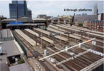
The Thameslink Programme at Network Rail involves a £5 billion upgrade of a major railway line through Central London, which aims to increase the number of carriages as well as the frequency of trains per hour. London Bridge Station is a major transport hub within the programme and is required to undergo a full refurbishment to accommodate for the upgrade. The station is currently comprised of 6 through tracks and 9 terminating tracks (Figure 1). The new development will consist of 9 through and 6 terminating tracks. The station is required to remain operational during all stages of the project.
Figure 1 - London Bridge Station pre-redevelopment
2.2 Engineering Needs
During operational activities Network Rail is required to minimise disruption to surrounding assets, not only those belonging to them but also those of third party owners. Any type of work which could potentially impact the structural stability or asset performance is required to be calculated and mitigated wherever possible. Therefore a monitoring strategy and specification is produced by the engineers which provides details of the predicted movement impacts along with the monitoring system to be implemented, including its accuracy and required frequency. The tracks and platforms are required to be monitored throughout the project as they fall within the zone of impact during demolition and construction work.
2.3 Issues with the Current System
For this project, the monitoring specification requires real-time and manual monitoring solutions. The monitoring specification dictates the use of robotic total stations measuring to prisms mounted on the sleeper adjacent to each running rail and on the platform wall along the length of platform and track. Rail twist and cant are also required to be calculated through these measurements. Even though this is the most conventional approach for railway monitoring there are some inherent disadvantages with the implemented system. Access to track requires significant notification periods which is time consuming and costly. Once access has been approved, instruments and prisms have to be fixed into position across the structure. It is an intrusive method which requires drilling and clamping in proximity to the track. Once installed the system is susceptible to missing data due to occluded lines of sight between the instrument and prisms due to passing trains. Finally, track monitoring systems require continuous maintenance: prisms require regular cleaning and can also be knocked or destroyed during engineering hours which can set off “false movement” triggers which then requires an engineer to analyse and investigate further, causing unnecessary delays and disruptions. As part of the monitoring specification, a backup system is legally required if the whole monitoring network were to break down for any reason.
3. METHOD
3.1 Data Acquisition
For the project two mainstream TLS systems from key manufacturers, denoted “Scanner A” and “Scanner B”, were used to scan the railway tracks at London Bridge Station. Scanner A uses the phase-based ranging principal with a The International Archives of the Photogrammetry, Remote Sensing and Spatial Information Sciences, Volume XL-5, 2014
manufacturer’s quoted ranging capability of 2 to 3mm RMS at the distances employed in this project. Scanner B is a hybrid time-of-flight system with a comparable manufacturer’s ranging specification.
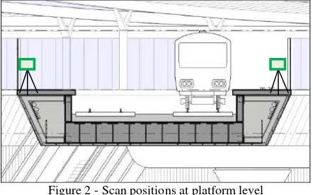
In order to comply with the health and safety regulations of working in proximity to live track, the scanners were setup 1.5 metres away from the edge of the elevated platform. Two 360° scans were carried out, one on each side of the platforms to enable both sides of the rail web to be captured. Figure 2 shows the approximate scanner positions with respect to the track in green.
Figure 2 - Scan positions at platform level
A combination of spheres and black and white checkerboard targets were used for registration and geo-referencing purposes. The targets were surveyed using a TS15i total station and a least squares network adjustment was carried out in MicroSurvey StarNet V7 (http://www.microsurvey.com/index.htm) to geo-reference the scans onto the site grid. The scans from both scanning systems were independently registered and geo-referenced in Leica Cyclone 8.0.4. In both cases target based registration reported a mean absolute error of 1mm.
Figure 3 shows a 1mm thick cross-section taken from a design model of track in comparison to the left running track scanned from Scanner A (centre) and Scanner B (right).
Figure 3 - Cross-section of track from design model, Scanner A (centre) and Scanner B (right)
Visual comparison of the registered scanner point clouds to the design model highlight many occlusions from the line of sight between the scanner position and track, as well as pixel “edge effects” characterised most notably for Scanner B, by systematic point traces directed back towards the scanner locations (despite the same filtering options applied when importing the data into Cyclone). These areas were manually cleaned up for the analysis. Data from the head (or top) of the rail is also much noisier from both scanners due to interaction between the scanner laser and the complex reflective surface formed on the steel as trains pass over it. However portions of the rail section do remain consistent between scans, for example the sides of
the rail, the web and the foot. These consistencies support measurement of web thickness and definition of the left web of the track.
3.2 Investigating Rail Geometry
To investigate the point cloud sections in more detail, cross-sections with a length of 500mm were extracted from the site scans. Given knowledge of UK rail design, a 500mm length of track can be assumed to be straight before curvature must be taken into consideration. This assumption was demonstrated by carrying out laboratory tests on a length of rail similar to that used at London Bridge which was scanned by Scanners A and B. Plane fits were applied to the web of the rail to demonstrate baseline measurement capabilities of the two scanners. The RMS of the residuals normal to the plane for scanner A was 0.62mm and 0.94mm for Scanner B. These results highlight the capabilities of the scanner as well as confirming the planarity. The sections cut from the point cloud (from the site work) were the closest to the scanner positions to warrant a well-populated cross-section. These were then compared against a reference 3D CAD rail model matching the UK specification of the rail on site.
CloudCompare (V2.5.4.1) was used to initially align the point clouds to the reference CAD model by selecting pairs of common points. A series of fine registrations in CloudCompare, using its default ICP algorithm, were then carried out to see which features from the point cloud aligned best to the reference model. This was done by breaking down the track into three sections: the rail head, rail web and rail foot. A registration of the whole section was also carried out.
A detailed comparison between the fine registrations was then carried out in Geomagic Qualify 2013 (http://www.geomagic.com/en/) which allows 2D and 3D comparisons to be mapped between a reference object (in this case the model of the rail) and a test object (in this case the point cloud). Results are shown in Section 4.
4. RESULTS AND ANALYSIS
4.1 Registration of Point Cloud to Model
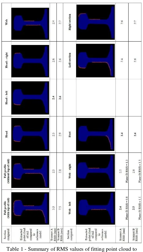
Table 1 summarises the RMS values from registering different sections of the point cloud (represented in orange) of the left running track from Scanners A and B to the 3D reference model (represented in blue). The table also shows the RMS of the plane fits to the left and right web of the rail.
The RMS of the registration of the entire section of track, including the head of the rail, shows a fit of 5.3mm and 7.5mm from Scanners A and B respectively. These values are expected due to the noise from the top of the head of the rail affecting the fit to the model. Data fitting to individual portions show a fairly consistent fit with all sections registering to below 3mm. Plane fits to both sets of scanner data show a better fit from the left web of the rail. The scanner positions were approximately 4m from the left of the web and 7m from the right of the web which highlights the quality of the scan at that range as the spot size hitting the surface is increasing. All the RMS values from Scanner A show slightly better fits than Scanner B, implying that data from Scanner B are slightly noisier.
From these results it can be established that the closer, left side of the section of track, consistently give the best fit to the model Rail Web
Rail Foot Rail Head
for both scanner types (shown in bold in Table 1). These areas can be considered as the most “trusted” when aligning to the track reference model. A further registration for this part of track was computed to compare capability between left hand (near) and right hand (far) sides of the rail (also shown in Table 1).
Table 1 - Summary of RMS values of fitting point cloud to modelled track
The results show that “globally” the left section of the track is able to fit to 2.4mm and 2.6mm from Scanners A and Scanner B respectively. This is compared to the points from the right hand side of the track producing an RMS of 2.6 and 2.7mm respectively for Scanner A and B. These results show that the fit to the 3D model is slightly better with the points from one scanner position. The reasons for this could be due to a smaller range from the scanner and therefore smaller spot size of the laser hitting the surface, or increased range noise due to decreased laser return strength with range. This test shows that the left side of the track: i.e. the head, web and rail of the track provides the best alignment to the 3D reference model with an RMS of 2.4mm and 2.6mm from Scanners A and B respectively. When both sides of the track profile are registered to the model the registration RMS increases to 2.5mm and 2.8mm respectively. However as this incorporates two different scans, the effect of the 1mm RMS target based registrations might have an effect on the overall fit. Overall, without the noise from the head of the rail data, all sections are able to fit to
the model with an RMS of better than 3mm. The next stage was to investigate the point cloud fits to the model in more detail by looking at the residuals of the RMS in Geomagic Qualify using the “2D Compare” tool. This tool allows the user to cut a cross section through the registered point cloud and model, allowing the deviations to be investigated.
4.2 2D Comparisons of Point Cloud to Model
A 2D comparison was applied to the side of the rail nearest to the scanner (left side). These results were compared to the full track profile with and without the rail head. Results are shown in Table 2. It shows histograms of the point deviations from the model from Scanner A and Scanner B.
Table 2 - 2D Comparison Results from Scanner A and B
Inspection of the histograms from each scanner shows that overall Scanner B has a consistent bias with the spread of residuals, of up to 5mm, skewed to the right. This implies a systematic error in the data from the scanner. This systematic bias in the data could be due to the accuracy of the scanning system as a whole. A way of verifying this would be to decrease the point cloud extraction area to see if the skewness was still present for a small sample of the point cloud profile. Scanner A, on the other hand, shows a small spread of residuals for the most trusted area followed by wider spread of residuals as more “areas” of the point cloud profile are added to the comparison. This shows that as the coverage of the track profile increases, other factors are affecting the quality of the fit, for example, the registration and quality of the right hand side of the scan from a longer range as well as the noise from the top of the head of the scan. From visual inspection of the histograms, it can be seen that some of the histograms might show a normal distribution of the residuals. Therefore a chi-squared test was carried out to test the “goodness of fit” to confirm whether or not the residuals were normally distributed. However results from the chi-square test show that the residuals from the 2D comparison technique do not show a normal distribution. Further inspection to determine this would require the sample data to be obtained, which is not currently available from Geomagic Qualify.
When looking back at previous related work, Liu et al (2011) were able to show a 2 to 3mm level of agreement between the mesh and ground truth. The results from this paper show equal levels of agreement but also highlight particular sections that show the best fit from a point cloud whilst reducing the number The International Archives of the Photogrammetry, Remote Sensing and Spatial Information Sciences, Volume XL-5, 2014
of processing steps required to achieve this. Oude Elberink et al (2014) also considered the point data but made a line extraction based on the rail head to achieve an RMS better than 2cm when compared to the final model. Results from the left section (side of the rail nearest to the scanner) track fitting described in this paper demonstrate fit from ICP of better than 3mm can be achieved which fits in with Oude Elberink et al’s (2014) suggestion of using the foot of the track to extract accurate rail geometry.
5. CONCLUSIONS AND FURTHER WORK
This paper has shown the quality of fit of a point could of a rail track profile to a reference 3D CAD model. In conclusion Scanner A, i.e. a phased based TLS system, shows that when applying an ICP algorithm and inspecting the residuals of the fit to a reference CAD model the most confident section of track geometry is the side of the rail nearest to the scanner (left side) with a fit of 2.4mm. Scanner B, i.e. a hybrid time-of-flight TLS system, also shows that the most confident section is left side of track with a fit of 2.6mm. Initial results of the chi-squared test implies that the residuals of the registration are not normally distributed, but further work on allowing the user to access the residuals from a 2D comparison is required. These results comply with previous findings whilst also highlighting the most confident regions that can be extracted and fitted accurately against a reference model of rail track.
As described earlier for large railway infrastructure projects there is a need for a backup monitoring system to be put in place should the current monitoring systems fail for whatever reason, or if direct access to track is not available. The results from this paper show the potential of using this type of static TLS setup for “spot checks” for monitoring track which would adhere to monitoring specification requirements and would require further work to deliver results in the format required by engineers. These results also show what could be achieved if a MLS system was employed to monitor the railway tracks or for asset management purposes. As there is a good proximity to the rails and visibility of the rail web and foot, there is a potential to carry out a more accurate rail extraction method based on both the web and foot of the rail track profile from the point cloud.
ACKNOWLEDGEMENTS
This research is based on a collaborative project funded by the EPSRC (Engineering and Physical Sciences Research Council) and Network Rail through the VEIV (Virtual Environments Imaging and Visualisation) Engineering Doctorate Centre at University College London. The authors would like to thank MicroSurvey for providing StarNet as well as the Costain Survey Team at London Bridge Redevelopment Project for enabling access to the site.
REFERENCES
Abellán, A., M. Jaboyedoff, et al. (2009). "Detection of millimetric deformation using a terrestrial laser scanner: experiment and application to a rockfall event." Natural
Hazards and Earth System Sciences 9(2): 365-372.
Arastounia, M. (2012). Automatic classification of LiDAR point clouds in a railway environment. MSc, University of Twente.
Berberan, A., M. Machado, et al. (2007). "Automatic multi total station monitoring of a tunnel." Survey Review 39(305): 203-211.
CloudCompare (version 2.5.4.1) [GPL software]. EDF R&D, Telecom ParisTech (2014). Retrieved from http://www.cloudcompare.org/.
Cooper, M. A. R. (1987). Control surveys in civil engineering, Collins London.
Cosser, E., G. W. Roberts, et al. (2003). Measuring the dynamic deformation of bridges using a total station. Proceedings, 11th FIG Symposium on Deformation Measurements, Santorini, Greece.
Lindenbergh, R. and N. Pfeifer (2005). "A statistical deformation analysis of two epochs of terrestrial laser data of a lock." Proc. of Optical 3D Measurement Techniques 2: 61-70.
Liu, C., X. L. Meng, et al. (2011). Precise 3D Measurements of the Roof Lab Railway Track with Ground Base Laser Scanning Technology and Its Relevance to High Speed Railway Track Monitoring. Joint International Symposium on Deformation Monitoring Hong Kong, China.
Monserrat, O. and M. Crosetto (2008). "Deformation measurement using terrestrial laser scanning data and least squares 3D surface matching." Isprs Journal of
Photogrammetry and Remote Sensing 63(1): 142-154.
Nuttens, T., C. Stal, et al. (2014). "Methodology for the ovalization monitoring of newly built circular train tunnels based on laser scanning: Liefkenshoek Rail Link (Belgium)."
Automation in Construction 43: 1-9.
Oude Elberink, S., K. Khoshelham, et al. (2013). "Rail track detection and modelling in mobile laser scanner data." ISPRS Annals of Photogrammetry, Remote Sensing and Spatial
Information Sciences 1(2): 223-228.
Psimoulis, P. A. and S. C. Stiros (2007). "Measurement of deflections and of oscillation frequencies of engineering structures using Robotic Theodolites (RTS)." Engineering
Structures 29(12): 3312-3324.
Standardization, E. C. f. (2008). Railway applications - Track - Track geometry quality. Part 1: Characterisation of track geometry. Brussels.
Tse, J. and J. Luk (2011). Design and Implementation of Automatic Deformation Monitoring System for the Construction of Railway Tunnel: A Case Study in West Island Line. 14th FIG Symposium on Deformation Measurement and Analysis, Hong Kong.
Van Gosliga, R., R. Lindenbergh, et al. (2006). "Deformation analysis of a bored tunnel by means of terrestrial laser scanning." Image Engineering and Vision Metrology. ISPRS Commission 36: 167-172.