which a high degree of structural continuity allows, means that more complex geometries than are possible with discontinuous structures can be adopted (Figs 5.17, 5.18 and 1.9).
Due to the ease with which continuity can be achieved and to the absence of the ‘lack-of-fit’ problem (see Appendix 3), in situreinforced
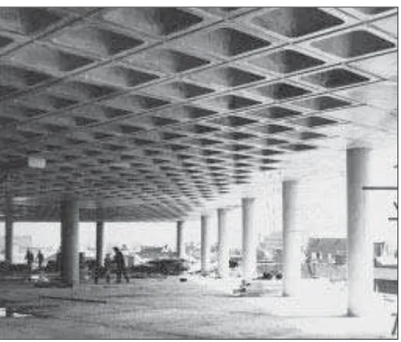
concrete is a particularly suitable material for continuous frames. The degree of continuity which is possible even allows the beams in a frame to be eliminated and a two-way spanning slab to be supported directly on columns to form what is called a ‘flat-slab’ structure (Figs 5.19 and 7.33). This is both highly efficient in its use of material and fairly simple to construct. The Willis, Faber and Dumas building (Figs 1.6, 5.19 and 7.37) has a type of flat-slab structure and this building demonstrates many of the advantages of continuous structures; the geometric freedom which structural continuity allows is
particularly well illustrated.
5.3 Semi-form-active structures
Semi-form-active structures have forms whose geometry is neither post-and-beam
nor form-active. The elements therefore contain the full range of internal force types (i.e. axial thrust, bending moment and shear force). The magnitudes of the bending moments, which are of course the most difficult of the internal forces to resist
efficiently, depend on the extent to which the shape is different from the form-active shape for the loads. The bending moments are significantly smaller, however, than those which occur in post-and-beam structures of equivalent span.
Semi-form-active structures are usually adopted as support systems for buildings for one of two reasons. They may be chosen because it is necessary to achieve greater efficiency than a post-and-beam structure would allow, because a long span is involved or because the applied load is light (see Section 6.2). Alternatively, a semi-form-active structure may be adopted because the shape of the building which is to be supported is such that neither a very simple post-and-beam structure nor a highly efficient fully form-active structure can be accommodated within it.
Figure 5.20 shows a typical example of a type of semi-form-active frame structure which is frequently adopted to achieve long spans in
constructed in steel, reinforced concrete or timber (Fig. 5.21). A variety of profiles and cross-sections are used for the frame elements, ranging from solid elements with rectangular cross-sections in the cases of reinforced concrete and laminated timber, to ‘improved’ elements in the case of steel. As with other
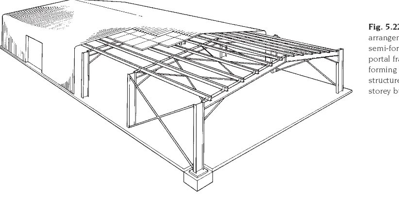
types of frame, the range of spans which can be achieved is large. In its most common form, this type of structure consists of a series of identical plane rigid frames arranged parallel to one another to form a rectangular plan (Fig. 5.22).
56
Fig. 5.20 The ubiquitous portal frame is a semi-form-active structure. The main elements in this example have ‘improved’ I-shaped cross-sections. (Photo: Conder)
Fig. 5.21 The efficiency of the semi-form-active portal frame is affected by the shapes of cross-section and longitudinal profile which are used. Variation of the depth of the cross-section and the use of I- or box-sections are common forms of ‘improvement’. The structure type is highly versatile and is used over a wide range of spans.
Fig. 5.22 A typical arrangement of semi-form-active portal frames forming the
buildings which have distinctive shapes (Figs iii and 5.23 to 5.25).
Included in this group are compressive shells, tensile cable networks and air-supported tensile-membrane structures. In almost all cases more than one type of element is required, especially in tensile systems which must normally have
compressive as well as tensile parts, and form-active shapes are frequently chosen for the compressive elements as well as for the tensile
by a designer who contemplates using this type of arrangement.
Form-active structures are almost invariably statically indeterminate and this, together with the fact that they are difficult to construct, makes them very expensive in the present age, despite the fact that they make an efficient use of structural material. The level of complexity which is involved in their design and
construction can be appreciated by considering just a few of the special design problems which
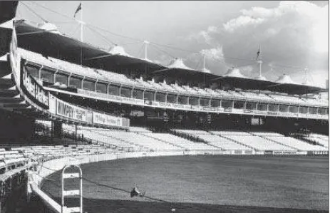
57 Fig. 5.23 Grandstand at Lord’s Cricket Ground, London, UK, 1987; Michael Hopkins & Partners, architects; Ove Arup &
they create. The tensile envelopes, for
example, always assume the form-active shape for the load which acts on them no matter what their initial geometry may have been. This is a consequence of their complete lack of
rigidity and it means that considerable care must be taken in their manufacture to ensure that the tailoring of the membrane or network is correct. If this is not done and a membrane with a non-form-active geometry is produced,
58
Fig. 5.24 Barton Malow Silverdome. A very large span is achieved here with a cable-reinforced air-supported membrane, which is a tensile form-active structure.
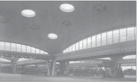
Fig. 5.25 Brynmawr Rubber Factory, Brynmawr, UK, 1952; Architects Co-Partnership, architects; Ove Arup & Partners, structural engineers. The principal enclosing elements here are compressive form-active, elliptical paraboloid shell roofs. (Photo: Architectural Review)
(a)
the form-active structure, the penalty which is incurred if it is not given the true form-active shape for the load is that bending stress occurs in the membrane. If this happens unintentionally there is a risk of strength failure, and it is therefore desirable that the exact geometry of the true form-active shape should be determined during the design process and that the structure be made to conform to it. Two problems arise, however. Firstly, the geometry of the form-active shape is very complex and is difficult to determine accurately, and thus difficult to reproduce exactly in a real structure. In particular, the radius of curvature of the surface is not constant and this makes both the analysis of the structure and its construction difficult. Secondly, real structures are always subjected to a variety of different forms of loading, which means that the required form-active shape changes as loads change. This does not present an insuperable problem in the case of tensile form-active-structures because, being flexible, these can simply adjust their geometry to take up the different shapes which are required. So long as the change in load is not too extreme, the necessary adjustment can be accommodated without the risk of serious wrinkles developing. Compressive forms must be rigid, however, and so only one geometry is possible. Therefore some bending stress will inevitably arise in a compressive form-active structure due to changes which occur to the
is rarely considered to be justified. A compromise is frequently made in which a doubly-curved shape, which is close to the form-active shape but which has a much simpler geometry, is adopted. These more practical shapes achieve greater simplicity either by having a constant radius of curvature, as in a spherical dome, or by being
translational forms, which can be generated by simple curves such as parabolas or ellipses. The hyperbolic paraboloid and the elliptical paraboloid (Fig. 5.25) are examples of the latter. These shapes are simpler to analyse and to construct than true form-active shapes and by adopting them the designer elects to pay the penalty of lower efficiency to achieve relative ease of design and construction.
5.5 Conclusion
In this chapter the three basic types of structural arrangement have been described and a small selection of each has been illustrated. A great number of variations is possible within each type, depending on the nature of the elements of which they are composed. An ability to place a structure within the appropriate category forms a useful basis for assessing its performance and the appropriateness of its selection for a particular application.