4.1 Introduction
This chapter is concerned with the relationship between structural form and structural
performance. In particular, the effect of structural geometry on the efficiency1with which particular levels of strength and rigidity can be achieved is explored.
The shapes of structural elements, especially the shapes of their longitudinal axes in relation to the pattern of applied load, determine the types of internal force which occur within them and influence the magnitudes of these forces. These two factors – the type and the magnitude of the internal force created by a given application of load – have a marked effect on the level of structural efficiency which can be achieved because they determine the
amount of material which must be provided to give the elements adequate strength and rigidity.
A classification system for structural elements is proposed here based on the relationship between form and efficiency. Its purpose is to aid the understanding of the role of structural elements in determining the performance of complete structures. It
therefore provides a basis for the reading of a building as a structural object.
4.2 The effect of form on internal
force type
Elements in architectural structures are subjected principally either to axial internal force or to bending-type internal force. They may also be subjected to a combination of these. The distinction between axial and
bending is an important one, so far as efficiency is concerned, because axial internal force can be resisted more efficiently than bending-type internal force. The principal reason for this is that the distribution of stress which occurs within the cross-sections of axially loaded elements is more or less constant, and this uniform level of stress allows all of the material in the element to be stressed to its limit. A size of cross-section is selected which ensures that the level of stress is as high as the material concerned can safely withstand and an efficient use of material therefore results because all of the material present provides full value for its weight. With bending stress, which varies in intensity in all cross-sections (Fig. 4.1) from a minimum at the neutral axis to a maximum at the extreme fibres (see Appendix 2), only the material at the extreme fibres can be stressed to its limit. Most of the material present is
understressed and therefore inefficiently used. The type of internal force which occurs in an element depends on the relationship between the direction of its principal axis (its
longitudinal axis) and the direction of the load which is applied to it (Fig. 4.2). If an element is straight, axial internal force occurs if the load is applied parallel to the longitudinal axis of the element. Bending-type internal force occurs if it
is applied at right angles to the longitudinal 37
The relationship
between structural form
and structural efficiency
axis. If the load is applied obliquely, a
combination of axial and bending stress occurs. The axial-only and bending-only cases are in fact special cases of the more general
combined case, but they are nevertheless the most commonly found types of loading arrangement in architectural structures.
If an element is not straight, it will almost inevitably be subjected to a combination of axial and bending internal forces when a load is applied, but there are important exceptions to this as is illustrated in Fig. 4.3. Here, the structural element consists of a flexible cable, supported at its ends, and from which various loads are suspended. Because the cable has no rigidity it is incapable of carrying any other type of internal force but axial tension; it is therefore forced by the loads into a shape which allows it to resist the loads with an internal force which is pure axial tension. The shape traced by the longitudinal axis is unique to the load pattern and is called the ‘form-active’2shape for that load.
As is seen in Fig. 4.3 the shape which the cable adopts is dependent on the pattern of load which is applied; the form-active shape is straight-sided when the loads are concentrated at individual points and curved if the load is distributed along it. If a cable is allowed simply to sag under its own weight, which is a
distributed load acting along its entire length, it adopts a curve known as a ‘catenary’ (Fig. 4.3).
An interesting feature of the form-active shape for any load pattern is that if a rigid element is constructed whose longitudinal axis is the mirror image of the form-active shape taken up by the cable, then it too will be subjected exclusively to axial internal forces when the same load is applied, despite the fact that, being rigid, it could also carry a bending-type internal force. In the mirror-image form all the axial internal forces are compressive (Fig. 4.4).
38
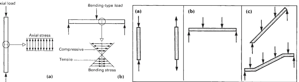
Fig. 4.1 (a) Elements which carry purely axial load are subjected to axial stress whose intensity is constant across all cross-sectional planes. (b) Pure bending-type load (i.e. load which is normal to the axis of the element) causes bending stress to occur on all cross-sectional planes. The magnitude of this varies within each cross-section from a maximum compressive stress at one extremity to a maximum tensile stress at the other.
Fig. 4.2 Basic relationships between loads and structural elements. (a) Load coincident with principal axis; axial internal force. (b) Load perpendicular to the principal axis; bending-type internal force. (c) Load inclined to the principal axis; combined axial and bending-type internal force.
2 ‘Form-active’ is a term applied by Engel in his book Structure Systems, 1967, to a structural element in which the shape of the longitudinal axis, in relation to the pattern of applied load, is such that the internal force is axial.
The cable structure and its rigid ‘mirror image’ counterpart are simple examples of a whole class of structural elements which carry axial internal forces because their longitudinal axes conform to the form-active shapes for the loads which are applied to them. These are called ‘form-active’ elements.
If, in a real structure, a flexible material such as steel wire or cable is used to make an element, it will automatically take up the form-active shape when load is applied. Flexible material is in fact incapable of becoming anything other than a form-active element. If the material is rigid, however, and a form-active element is required, then it must be made to conform to the form-active shape for the load which is to be applied to it or, in the case of a compressive element, to the mirror image of the form-active shape. If not, the internal force will not be pure axial force and some bending will occur.
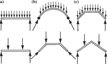
Figure 4.5 shows a mixture of form-active and non-form-active shapes. Two load patterns
are illustrated: a uniformly distributed load across the whole of the element and two concentrated loads applied at equal distances across them. For each load, elements (a) carry pure bending-type internal forces; no axial force can occur in these because there is no component of either load which is parallel to the axis of the element. The elements in (b) have shapes which conform exactly to the form-active shapes of the loads. They are therefore form-active elements which carry axial internal forces only; in both cases the forces are compressive. The elements (c) do not conform to the form-active shapes for the loads and will not therefore carry pure axial internal force. Neither will they be subjected to pure bending; they will carry a combination of bending and axial internal force.
So far as the shape of their longitudinal axes are concerned, structural elements can thus be classified into three categories: form-active elements, non-form-form-active elements and semi-form-active elements. Form-active elements are those which conform to the form-active shape of the load pattern which is applied to them and they contain axial
internal forces only. Non-form-active elements are those whose longitudinal axis does not conform to the form-active shape of the loads and is such that no axial
component of internal force occurs. These contain bending-type internal force only. Semi-form-active elements are elements whose shapes are such that they contain a combination of bending and axial internal forces.
It is important to note that structural elements can only be form-active in the context of a particular load pattern. There are no shapes which are form-active per se. The cranked beam shape in Fig. 4.5, for example, is a fully form-active element when subjected to the two concentrated loads, but a semi-form-active element when subjected to the
uniformly distributed load.
Form-active shapes are potentially the most efficient types of structural element and non-form-active shapes the least efficient. The
efficiency of semi-form-active elements 39
Fig. 4.4 Compressive form-active shapes.
Fig. 4.5 Examples of the relationship between element shape, load pattern and element type. The latter is determined by the relationship between the shape of the element and the form-active shape for the load pattern which it carries. (a) Non-form-active (bending stress only). (b) Form-active (axial stress only). (c) Semi-form-active (combined bending and axial stress).
depends on the extent to which they are different from the form-active shape.
4.3 The concept of ‘improved’
shapes in cross-section and
longitudinal profile
It will be remembered from the beginning of Section 4.2 that the main reason for the low efficiency of elements in which bending-type internal forces occur is the uneven distribution of stress which exists within every cross-section. This causes the material in the centre of the cross-section, adjacent to the neutral axis (see Appendix 2), to be under-stressed and therefore inefficiently used. The efficiency of an element can be improved if some of the under-stressed material is removed and this
can be achieved by a judicious choice of geometry in both cross-section and longitudinal profile.
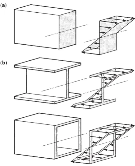
Compare the cross-sections of Fig. 4.6 with the diagram of bending stress distribution. Most of the material in the solid rectangular cross-section is under-stressed; the load is actually carried principally by the material in the high stress regions of the cross-section which occur at its top and bottom extremities (the extreme fibres). In the I- and box-shaped cross-sections most of the under-stressed material is eliminated; the strength of
elements which are given these cross-sections is almost as great as that of an element with a solid rectangular cross-section of the same overall dimensions; they contain significantly less material and are therefore lighter and more efficient.
A similar situation exists with slab-type elements. Solid slabs are much less efficient in their use of material than those in which material is removed from the interior, as can be demonstrated by carrying out a simple experiment with card (Fig. 4.7). A flat piece of thin card has a very low bending strength. If the card is arranged into a folded or corrugated geometry the bending strength is greatly increased. The card with the folded or
corrugated cross-section has a strength which is equivalent to that of a solid card with the same total depth; it is, however, much lighter and therefore more efficient.
In general, cross-sections in which material is located away from the centre are more efficient in carrying bending-type loads than solid cross-sections. Solid cross-sections are, of course, much simpler to make and for this reason have an important place in the field of architectural structures, but they are poor performers compared to the I- or box-shaped cross-section so far as structural efficiency is concerned. In the classification which will be proposed here, these two categories of cross-section are referred to as ‘simple solid’ and ‘improved’ cross-sections.
The shape of an element in longitudinal profile can be manipulated in a similar way to its cross-section to improve its performance in
40
Fig. 4.6 The effect of cross-section shape on the efficiency of elements which carry bending-type loads. (a) In an element with a rectangular cross-section, high bending stress occurs at the extreme fibres only. Most of the material carries a low stress and is therefore inefficiently used. (b) In ‘improved’ cross-sections efficiency is increased by elimination of most of the understressed material adjacent to the centre of the cross-section.
(a)
resisting bending-type loads. The adjustment can take the form of alteration to the overall shape of the profile or to its internal
geometry.
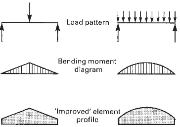
To improve efficiency the overall shape is adjusted by varying the depth of the element: this is the dimension on which bending strength principally depends (see Appendix 2). If the depth is varied according to the intensity of bending (specifically to the magnitude of the bending moment) then a more efficient use of material is achieved than if a constant depth of cross-section is used. Figure 4.8 shows two beam profiles which have been improved in this way. They are deep at the locations where
the bending moment is high and shallow where it is low.
The internal geometry of the longitudinal profile can also be improved by altering it to remove under-stressed material from the interior of the element. Examples of elements in which this has been done are shown in Fig. 4.9. As in the case of cross-sectional shape the internal geometry of the longitudinal profile of an element will be referred to here as ‘simple solid’ or ‘improved’.
One type of ‘improved’ profile which is of great importance in architectural as well as all other types of structure is the triangulated profile (i.e. the profile which consists entirely of triangles) (Fig. 4.10). If an element of this type has loads applied to it at the vertices of the triangles only, then the individual sub-elements which form the triangles are Fig. 4.7 The effect of cross-sectional shape on the
efficiency with which bending-type load is resisted. (a) Thin card which has an inefficient rectangular cross-section. (b) Thin card folded to give an efficient ‘improved’ cross-section. (c) Thick card with inefficient rectangular cross-section and having equivalent strength and stiffness to the folded thin card.
(a)
(b)
(c)
Fig. 4.8 The efficiency of a non-form-active element can be improved if its longitudinal profile is adjusted to conform to the bending moment diagram so that high strength is provided only where the internal force is high.
41
subjected to axial internal forces only3(Figs 4.11 and 4.12). This applies no matter what the relationship is between the pattern of loads and the longitudinal axis of the element, taken as a whole.
By eliminating bending stress from non-form-active elements the triangulated internal geometry allows a high degree of structural efficiency to be achieved. The advantage of the triangulated element over the other class of element for which this is true – the form-active element – is that no special overall form is
required to produce the axial-stress-only condition. All that is required is that the internal geometry be fully triangulated and the external load applied only at the joints.
Triangulated elements do not, however, achieve quite such a high degree of structural efficiency as form-active structures due to the relatively high level of internal force which occurs.
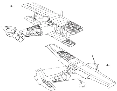
Certain bending-type elements with ‘improved’ cross-sections are referred to as ‘stressed skin’, ‘monocoque’ or ‘semi-monocoque’ elements to distinguish them from skeletal elements which consist of a framework of structural sub-elements covered by non-structural skin. The distinction is perhaps best seen in the field of aeronautical engineering by comparison of the structure of a fabric-covered ‘stick-and-string’ biplane with that of an all-metal aircraft (Fig. 4.13). In each case the fuselage is a structure which carries bending as well as other types of internal force, notably torsion. Aircraft structures must, of course, have a very high ratio of strength to weight. Form-active or semi-form-active arrangements are impractical, however,
42
3 This property is a consequence of a characteristic unique to the triangle among geometric figures, which is that its geometry can only be changed if the length of one or more of its sides is altered. (The geometry of any other polygon can be changed by altering the angles between the sides and maintaining the sides at a constant length – Fig. 4.11.) The resistance which is generated by a triangulated structure to a potential alteration in geometry (which is what occurs when a load is applied) takes the form of a resistance to change in length of the sides of the triangles. This results in the sub-elements which form the sides of the triangles being placed into either axial tension or axial compression. The axial-stress-only state therefore occurs no matter what the overall form of the element, provided that its internal geometry is fully triangulated with straight-sided triangles and the load is applied only to the joints between the sub-elements. If a load is applied directly to one of the constituent sub-elements and not at a joint, as in Fig. 4.12, then bending will occur in that sub-element.
Fig. 4.10 A solid beam is less strong and rigid than a triangulated structure of equivalent weight.
Fig. 4.12 The axial-internal-force-only condition does not occur if load is applied to a triangulated structure other than at its joints.
because the overall shapes of aircraft are determined from aerodynamic rather than structural considerations. The structures are therefore non-form-active and must have ‘improved’ internal structures so as to meet the required levels of efficiency.
In the case of the early biplane fuselage the fabric skin had virtually no structural function and the loads were carried entirely by the framework of timber and wire which, being
fully triangulated, was an efficient type of structure with a high ratio of strength to weight. Its disadvantage was that its potential strength was limited firstly by the relative weakness of timber, and secondly by the difficulty of making efficient joints between the timber compressive elements and the wire tensile elements. As the size and speed of aircraft increased and stronger aircraft
structures were required, the change to an all-metal structure became inevitable. The fabric skin was replaced by sheeting of aluminium alloy and the internal structure of timber and wire by ribs and longitudinal stringers also of aluminium alloy. In this more sophisticated type of aircraft structure, which is called a semi-monocoque structure, the metal skin acted with the ribs and stringers to form a composite structure called a ‘stressed-skin semi-monocoque’. Monocoque construction is the term used where the element consists only
of the stressed skin. 43
Fig. 4.13 The overall shapes of aircraft are determined mainly from non-structural considerations, principally aerodynamic performance requirements. The supporting structures are therefore non-form-active, but the very high priority which must be given to saving of weight results in the adoption of configurations in which many
‘improvements’ are incorporated. (a) The fuselage and wings of the ‘stick-and-string’ biplane have triangulated structures of timber and wire. The fabric covering has a minimal structural function. (b) The wings and fuselage of the all-metal aircraft are hollow box-beams in which the skin plays an essential structural role.
(a)
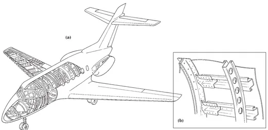
In the semi-monocoque fuselage of an all-metal aircraft (Fig. 4.14), which is a
non-form-active structural element with an ‘improved’ cross-section, a very thin stressed skin is used which must be strengthened at regular intervals by ribs and stringers to prevent local buckling from occurring. The technique of improvement may be seen to be operating at several levels. The fuselage, taken as a whole, is a non-form-active element with an ‘improved’ hollow-tube cross-section. Further ‘improvement’ occurs in the tube walls, which have a complex cross-section consisting of the stressed skin acting in conjunction with the strengthening ribs and stringers. These strengthening sub-elements are in turn
‘improved’ by having cross-sections of complex shape and circular holes cut in their webs.
The all-metal aircraft structure is therefore a complicated assembly of sub-elements to which the technique of ‘improvement’ has been applied at several levels. The complexity results in a structure which is efficient but which is very costly to produce. This is justified
in the interests of saving weight. Every kilonewton saved contributes to the
performance of the aircraft so weight saving is allocated a very high priority in the design.
A similar application of the features which save weight can be seen in the field of vehicle design, especially railway carriages and motor cars. The structure of the modern railway carriage consists of a metal tube which forms its skin, spanning as a beam between the bogies on which it is mounted. It is a non-form-active ‘improved’ box beam. The structure of a motor car is similar: the steel car body acts as a beam to carry the weight of the engine, occupants, etc. between the road wheels (Fig. 4.15). As in the case of the aeroplane the overall forms of rail and road vehicles are determined largely from non-structural considerations, but the need to save weight is given a high priority in the design. Again the use of ‘improved’ non-form-active monocoque and semi-monocoque structures constitutes a sensible response to the technical problems posed.
44
Fig. 4.14 The fuselage of the all-metal aircraft is a non-form-active structure which is ‘improved’ at various levels. The fuselage, taken as a whole, is a hollow box-beam. ‘Improvements’ of several types are incorporated into the sub-elements which support the structural skin.
(a)
The use of such elaborate forms of ‘improvement’ as the monocoque or semi-monocoque stressed skin can rarely be justified on technical grounds in architectural structures because the saving of weight is not a sufficiently high priority to justify the expense of this complex type of structure. In the case of buildings, inefficient high-mass structures can actually be advantageous. They add thermal mass and their weight counteracts wind uplift.
The uses of the devices and configurations which produce efficient and therefore
lightweight structures – the complex cross-section, the circular ‘lightening’ hole, triangulation of elements and profiling to conform to bending moment diagrams – are not always appropriate from the technical viewpoint in the context of architecture where they are justified technically only in situations in which an efficient, lightweight structure is required (see Chapter 6). They can, however, have another architectural function which is to form a visual vocabulary of structure.
The use of the devices associated with structural efficiency for stylistic purposes is discussed in Chapter 7. It might be observed here that where this occurs they are often used in situations which are inappropriate
structurally. The devices of ‘improvement’ which were devised in the context of aeronautical and vehicle engineering have become, in the hands of modern architects,
especially those of ‘high-tech’ architects, a visual version of the dead metaphor.
4.4 Classification of structural
elements
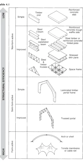
The principles outlined in the preceding sections, concerned with the various devices which can be used to improve the efficiency of structures, can form the basis of a
classification system for structural elements. This is illustrated in Table 4.1. The primary categorisation is between form-active, semi-form-active and non-semi-form-active elements because this is the most important factor in determining the level of efficiency which can be achieved. Elements are further classified according to the degree of ‘improvement’ which is present in their cross-sections and longitudinal profiles. The number of
combinations and permutations is very large and a selection only of possibilities is illustrated in Table 4.1 to show the general principles involved. The least efficient shapes (non-form-active elements with simple shapes in both cross-section and longitudinal profile) are placed at the top of the table and the degree of efficiency present increases towards the bottom of the table, where the most efficient shapes – tensile form-active elements – are placed. A
distinction is made between line elements, 45
Fig. 4.15 The metal body of a motor car is an ‘improved’ non-form-active beam which spans between the road wheels.
(a)
such as beams, in which one dimension is significantly larger than the other two, and surface elements, such as slabs, in which one dimension is significantly smaller than the other two.
This system links the form, and therefore the appearance, of a structure with its
technical performance and provides a basis for reading a building, or indeed any artefact, as a structural object. This is an important
consideration for anyone involved with either the design of buildings or with their critical appraisal.
The system is based on the idea of efficiency: structural elements are classified according to the level of efficiency which they make possible in the resistance of load which is, of course, their principal function. The main objective of structural design, however, is the achievement of an appropriate level of efficiency rather than the maximum possible level of efficiency. The factors which determine the level of efficiency which is appropriate are discussed in Chapter 6. The discussion of whether or not an appropriate level of
efficiency has been achieved cannot take place, however, in the absence of a means of judging efficiency. The system proposed here provides that means.
An aspect of the relationship between structure and architecture which has been touched on in this chapter is the possibility that the features associated with structural efficiency can be used as the basis of a visual vocabulary which conveys architectural meaning – the message being technical progress and excellence. This issue is discussed in Section 7.2.2.
46
Table 4.1
HIGH
STRUCTURAL
EFFICIENCY