SHAPE FUNCTION-BASED ESTIMATION OF DEFORMATION WITH MOVING
CAMERAS ATTACHED TO THE DEFORMING BODY
O. Jokinena,∗, I. Rantab, H. Haggr´ena, P. R¨onnholma
a
Department of Built Environment, Aalto University, FI00076 Aalto, Finland [email protected], (henrik.haggren, petri.ronnholm)@aalto.fi b
Mapvision Ltd., FI-00390 Helsinki, Finland - [email protected]
Commission V, WG V/1
KEY WORDS:3-D deformation, Shape function, Close-range imagery, Moving cameras, Single image, Crane
ABSTRACT:
The paper presents a novel method to measure 3-D deformation of a large metallic frame structure of a crane under loading from one to several images, when the cameras need to be attached to the self deforming body, the structure sways during loading, and the imaging geometry is not optimal due to physical limitations. The solution is based on modeling the deformation with adequate shape functions and taking into account that the cameras move depending on the frame deformation. It is shown that the deformation can be estimated even from a single image of targeted points if the 3-D coordinates of the points are known or have been measured before loading using multiple cameras or some other measuring technique. The precision of the method is evaluated to be 1 mm at best, corresponding to 1:11400 of the average distance to the target.
1. INTRODUCTION
Image-based deformation measurement is typically based on a stationary camera set-up. The object points are measured before and after deformation, and the difference tells the object defor-mation. The cameras may also move but then there is something in the object space which remains the same so that the orientation of the cameras can be solved before and after deformation with respect to a common coordinate system.
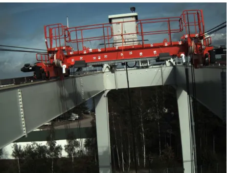
However in this paper, we are facing a measurement task, where these assumptions are no longer valid. The task deals with mea-suring the deformation of a large metallic frame structure of a crane when it is loaded with a weight of 40000 kg. The size of the frame is25×8m and it is located at a height of 25 m. Fig-ure 1 shows a view of one camera illustrating the frame structFig-ure and a carriage across the frame in the middle of the longitudinal direction. Due to physical limitations, the cameras need to be at-tached to the deforming frame so that they move when the object deforms neither there is anything stable in the scene which could be used to link the camera orientations to the same system before and after deformation. The structure also sways during loading so that the image capturing needs to be synchronized. The cam-eras are considered to move from one orientation to another and the measuring to occur in temporary static conditions in both ori-entations.
The lack of a stable datum for deformation estimation has been previously addressed by considering only relative changes deter-mined, e.g., by aligning the point sets so that the difference in the direction of one coordinate is minimized (Fraser and Gustafson, 1986). Another approach is proposed by Papo (1986), where a free net adjustment is extended with additional parameters and constraints, which enable to remove the datum defect. Shahar and Even-Tzur (2014) use the same principle to extract a datum area, where changes are due to deterministic dynamics and can be estimated. Deformation of the rest of the network is obtained after cleaning the deterministic component from the data.
∗Corresponding author
Figure 1: Frame and carriage of a crane to be measured.
We propose to address the crane deformation problem by mod-eling the deformation with appropriate shape functions, the pa-rameters of which are solved in a least squares adjustment mini-mizing the difference between observed and modeled image co-ordinates of circular target points attached onto the object. The shape functions constrain the problem so that it becomes solv-able. The key issue is to find shape functions which adequately describe the deformation and then, to determine the dependence of modeled image observations on the shape function parameters.
esti-mated to account for rigid changes in orientations and a non-rigid change or deformation of the object. To regularize the problem, constraints are typically included for the shape of the deforma-tion (Hirshberget al., 2012). For example, Chui and Rangarajan (2003) assume that the deformation can be presented as a thin-plate spline, while Rueckertet al.(1999) apply B-splines, which can better describe local deformations. Small local deformations may be also recovered using elastic models (Bajcsy and Kovacic, 1989). If certain structures of the object should not change the shape, a penalty term may be included which forces the trans-formation to be rigid in that region (Loeckxet al., 2004). In many cases, the shape is represented as a linear combination of shape bases and the measurements include only image observa-tions. The non-rigid shape and motion are then solved using rank constraints on the measurement matrix and orthonormality con-straints on camera rotations (Bregleret al., 2000; Brand, 2001; Torresani et al., 2001), while Xiaoet al. (2006) show that a unique solution is obtained when basis constraints are also in-cluded. Fayadet al. (2009) extend the method to a quadratic deformation model, which is able to cope with object bending, stretching, shearing, and twisting. Most of these approaches that utilize shape bases assume an orthographic camera projection model, while Hartley and Vidal (2008) propose an algorithm for a perspective camera.
For the crane deformation, however, we can do more than just non-rigid registration as changes in the camera orientations are not arbitrary but directly dependent on the frame deformation. Further, we need not reconstruct the 3-D points after deforma-tion explicitly, but only the shape funcdeforma-tion parameters are solved, which can be used to evaluate the deformation at any point. As measurements, we also use only the image coordinates of the tar-get points in a single image or optionally in multiple images after deformation. Ranta (2015) studies the same problem but registers the 3-D object points before and after deformation by assuming that one beam of the structure remains unchanged which leads to less accurate deformation estimation. Our main contribution is thus to couple changes in the cameras orientations with the object deformation for estimation of deformation with high precision.
The paper is organized as follows. The methods are described in Section 2 including description of the object geometry and cam-era set-up, introducing a mathematical model for the deformation utilizing shape functions, deriving the influence of deformation on the camera orientations, and solving the deformation by least squares adjustment. Experimental results are discussed in Section 3 and conclusions are presented in Section 4.
2. METHODS
2.1 Object Geometry and Camera Set-up
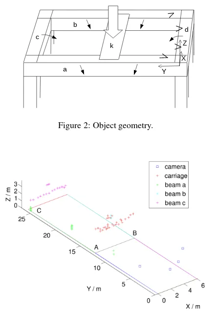
The object geometry is illustrated in Fig. 2. It consists of a metal-lic frame supported by four columns at the corners. The frame is not anchored but stands on wheels. In the middle of the longi-tudinal direction, there is a carriage k across the frame, which is loaded with a heavy weight. Due to loading, the carriage bends downwards. This causes beams a and b to bend downwards and slightly towards the carriage since the beams are assumed non-stretchable. Beams a and b drag also beams c and d towards the carriage, while the columns bend slightly. Four calibrated indus-trial Mightex SME-C050-U cameras of resolution of2560×1920
pixels are attached to the beams: one at beam a, one at beam b, and two at beam d. The camera viewing directions are towards beam c. The imaging geometry is not optimal for high measur-ing accuracy but dictated by physical limitations. The interior
orientations of the cameras are assumed to remain stable during loading as the camera optics are locked. The image capturing is synchronized with a hardware trigger in order to cope with considerable swaying of the structure that occurs during loading. To measure the deformation, circular target points are evenly at-tached to the carriage and beam c (see Fig. 1). In addition, some bolts visible on beams a and b are used as measurement targets. For solving the scale of photogrammetric measurements, a scale bar with a known length is attached to the carriage. The scale bar moves but does not deform when the structure is loaded.
a b
d c
k
Y X
Z
Figure 2: Object geometry.
Figure 3: Measured target points and camera locations in the ob-ject coordinate system before loading.
also, the exterior orientations are computed with respect to the object coordinate system. The lines in Fig. 3 help to illustrate the inner outline of the frame. The line between points A and B is the intersection of the Xplane with a plane perpendicular to the Y-axis and passing through the center of points on the carriage. The same holds for the line below points on beam c. Point C is the Y-axis intercept of a plane perpendicular the Y-axis and passing through the center of points on beam c.
2.2 Model for Object Deformation
The object is assumed to deform according to the following math-ematical model. The carriage bends downwards according to a shape function
∆Z=f(YA, α) +βX(X−XB), (1) whereαandβare unknown parameters andf(YA, α)is the de-formation of beam a at point A.
Beam a deforms downwards according to another shape function
∆Z=αY(Y −YC)≡f(Y, α). (2) This model implicitly assumes that the maximum deformation in Zappears atYD=YC/2. More complex models such as piece-wise defined polynomials of second degree (a different polyno-mial for the part of beam a which is in front of the carriage and which is behind of the carriage) should thus be used if the car-riage is not placed in the middle of the longitudinal direction of the frame. Since beam a is assumed non-stretchable, the length |g(Y,∆Y, α)|of the deformation curve∆Z=f(Y, α)from the mid point to the deformed point equals the distance from the mid point to the measurement point before deformation. Thus, defor-mation∆Y(α)is solved from the equation Equation 4 is nonlinear in∆Y. It is thus solved iteratively. Let Yh=h(YC−YD)/H,h= 0, . . . , H, whereH= 1000. Since g(Y,0, α)is increasing in the intervalY ∈[YD, YC], an initial estimate for∆Y is obtained by finding the valueh=L, where the sequence
g(Yh,0, α)− |Y −YD|, h= 0, . . . , H (5) changes the sign. The initial estimate is then
∆Y0=YD+ (YL−YD)sgn(Y −YD). (6) For the refinement of the initial estimate, Eq. 4 is linearized and at each iteration, the correction∆VTis obtained from
∆VT=
Deformation of beam c is modeled as a rotation around a line parallel to the X-axis and having an equationY = YC, Z = ZE, whereZE(α) and the rotation angleθ(α) depend on the deformation of beam a. The rotation angle is obtained from the slope of normal of curve in Eq. 2 atY =YC+ ∆YC. It is given by
θ(α) =arccot(−1/(α(YC+ 2∆YC))). (8) The coordinateZEis the intercept of the normal with lineX =
0, Y =YCgiven after some simplification by
ZE(α) =α(YC+ ∆YC)∆YC+ ∆YC/(α(YC+ 2∆YC)). (9)
Beam d is assumed to deform similarly as beam c except that the rotation is around lineY = 0, Z=ZEby angle−θ.
2.3 Changes in Camera Orientations
Due to object deformation, the projection centers of cameras on beams a and b change by ∆YCam and∆ZCam similarly as the measurement points move according to Eqs. 2 - 7. The cam-era rotations change by a rotationRX(ϕ)around a line paral-lel to X-axis and passing through the changed camera location. The rotation angle is obtained from the slope of tangent of curve
∆Z=f(Y, α)at the changed camera location and it is given by
ϕ(α) = arctan(α(2(YCam+ ∆YCam(α))−YC)). (10) Small corrections by rotationsRX(ωa)andRZ(κa)around lines parallel to the X-axis and twice rotated Z-axis, respectively, and passing through the changed camera location are included to com-pensate for swaying of the object during loading. The changed rotation matrix of the camera on beam a is obtained from
Ranew=R a
oldRZ(κa)RX(ωa)RX(ϕ), (11)
whereRa
oldis the rotation matrix before loading. A similar for-mula holds for the camera on beam b.
The cameras on beam d rotate by−θ(α)around a line parallel to the X-axis and passing through(0,0, ZE). Small corrections of rotations around lines parallel to the X-axis and twice rotated Z-axis and passing through(0,0, ZE)are also included so that
Rdnew=RdoldRZ(κd)RX(ωd)RX(−θ). (12) The changed camera location is given by
tdnew=tE+RX(θ)RX(−ωd)RZ(−κd)(tdold−tE), (13)
where tdold is the translation vector before loading and tE = [0,0, ZE]T.
2.4 Least Squares Adjustment
According to the collinearity equations, the measured image co-ordinatesxik, yikof target pointiin camerakafter deformation are related to the object coordinatesXik, Yik, Zikin the camera coordinate system of camerakafter deformation by
xik+vxik=−ckXik/Zik≡x′ik yik+vyik=−ckYik/Zik≡yik′
(14)
whereckis the camera constant of camerak, the image coordi-nate origin is in the principal point, andvxik, vyikare residuals in thexandydirections, respectively. Further, we have
[Xik, Yik, Zik]T=Rnewk ([X d
where the deformed object coordinates
[Xid, Yid, Zid]T= [Xi, Yi+ ∆Yi, Zi+ ∆Zi]T (16)
and the changed rotation matricesRk
new and translation vectors
tknew depend on the shape function parametersα, βand on the rotation anglesωk, κk(two parameters for each camerak). For Kcameras, there are thus2 + 2Kparameters, which are solved by minimizing the merit function
χ2= wherewikare weights. The weightwikequals one if the dif-ferences between the measured and modeledxikandyik coor-dinates are both below an adaptive threshold. The threshold is based on the mean and standard deviation of differences in the im-age coordinates of points having positive weight at the previous iteration, and it gets tighter as the iteration proceeds similarly as proposed for registration of curves and surfaces by Zhang (1994). Otherwise, the weight equals zero, and also when the point is not visible in camerak.
The minimization problem is solved using the Levenberg-Marq-uardt algorithm. Consequently, the derivatives with respect to the unknown parameters are needed. These can be derived using elementary calculus after figuring out how the modeled image coordinates depend on the parameters. For points on the carriage,
x′ b by differentiating Eq. 4 with respect toα. It yields
− 1
from which we can solve
∂(∆Yi)
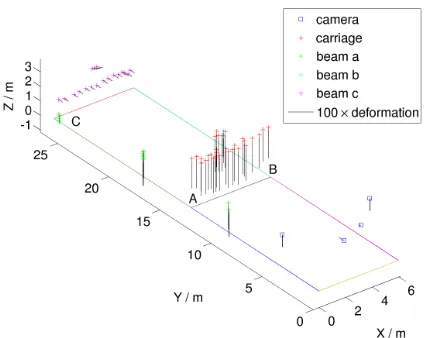
The results of deformation estimation with all the four cameras are illustrated in Fig. 4. It shows that the points on the carriage and beams a and b move mainly downwards while the points on beam c move mainly towards the carriage. The cameras on beam d move also mainly towards the carriage and the cameras on beams a and b move mainly downwards. In order to verify that the solution is correct, the 3-D points after deformation are projected onto the images using the changed orientations. Figure 5 shows the projected points as red plus signs, which correctly hit the image targets visible by this camera.
The method was then tested with different number of cameras
Figure 4: Direction and 100 times the magnitude of movement of target points and camera locations due to object deformation.
Figure 5: 3-D points (red plus signs) projected onto the image after deformation. The image has been cropped (zoom in to see the red plus signs).
ranging from one to four cameras and with all the possible 15 combinations of them. The method worked in all cases except in two, where the deformation in the middle of beam a and in the middle of beam b was larger than in the middle of the carriage. The parameterβwas negative in these cases, which is unnatu-ral. The mean and standard deviation of quantities that character-ize the deformation are given in Table 1 calculated using all the combinations of the cameras. The maximum deformations are reported in the middle of the carriage and in the middle of beam a or beam b. The RMSE gives the difference between the measured image coordinates and the 3-D points projected to the image after deformation using all the points, while the square root of the merit functionχ2is based only on points with a positive weight. The standard deviations describe the variation due to different camera configurations. For the carriage with well-defined target points, a standard deviation of 1 mm is achieved while for beams a and b, the standard deviation is larger as the bolt targets are more un-certain to measure and they are also located farther away from the cameras on the average. These standard deviation values are regarded as experimentally estimated precisions of the quantities mentioned, although the number of camera combinations is quite
Mean Std Max deformation of carriage / mm -25 1 Max deformation of beams a and b / mm -22 6 Rotation angleθof beam c / degrees 0.19 0.05 RMSE of all image points / pixels 0.92 0.30
(χ2)1/2/ pixels 0.31 0.06
small. No ground truth for the deformations was available so that the accuracy of the method could not be verified. The swaying of the structure also limits alternatives that might possibly be used for acquiring such reference data.
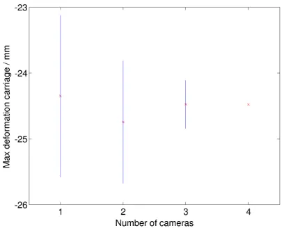
Figure 6: Deformation in the middle of the carriage±sample standard deviation as a function of the number of cameras.
Figure 7: Deformation in the middle of beam a or beam b± sample standard deviation as a function of the number of cameras.
Figure 8: Rotation angle of beam c±sample standard deviation as a function of the number of cameras.
The dependence of the method on the number of cameras is fur-ther studied in Figs. 6 - 8, which show the deformation in the middle of the carriage where it is at its maximum, the deforma-tion in the middle of beam a or beam b, and the rotadeforma-tion angle of beam c, respectively. The red crosses are the deformation or rotation angle values averaged over all combinations of cameras possible for the given number of cameras. For 1, 2, and 3 cam-eras, there are thus 4, 6, and 4 combinations, respectively. The blue lines show the uncertainty given by the standard deviation of the deformation values. For four cameras, there is only one combination so that the standard deviation is not defined. It can be seen that the estimation of deformation is possible using only a single camera although the lowest uncertainty is obtained for three cameras.
Figure 9: Analytically derived precision of deformation in the middle of the carriage and in the middle of beam a or beam b as a function of the number of cameras.
Figure 10: Analytically derived precision of the rotation angle of beam c as a function of the number of cameras.
com-binations of cameras. Possible reasons for this include that the method is sensitive to image viewpoint or there are systematic er-rors caused by inaccuracies in interior or exterior orientation, or that the mathematical model for deformation does not perfectly describe the true deformation. The considerable swaying of the structure during loading is considered to be the main reason as it causes deformations which have not been modeled although the orientations of the cameras are corrected by small rotations. According to the specifications of the cameras used, the camera trigger delay is less than 0.2 ms, which describes the uncertainty in synchronization of image capturing. However, the obtained standard deviation of 1 mm for the maximum deformation of the carriage is better than the measuring tolerance of 4 mm set by the manufacturer of the crane. When three cameras are used, the standard deviation of deformation in the middle of beam a or beam b is 0.7 mm, which is also below the tolerance. For com-parison, the iWitness software reports overall accuracies of 7 mm and 6 mm for the 3-D object points before and after deformation, respectively, so that estimating the deformation as a difference between the object coordinates does not give satisfactory results. According to iWitness, the imaging geometry is moderate and the smallest angles of intersection of 3-D points are10.7◦. The esti-mated accuracy of image referencing before deformation is 0.16 pixels, which also affects the precision of the scale determined by measuring the image coordinates of circular targets at both ends of the scale bar. The length of the scale bar is known with an accuracy of 0.001 mm. However, we note that for the proposed method, all random errors in image measurements, orientations, scale, and 3-D points are included and fully accounted for in the covariance matrix of the shape function parameters, which is used to estimate the analytically derived precision values.
4. CONCLUSIONS
The paper has presented a new method to estimate the deforma-tion of a large frame structure in challenging condideforma-tions, where the imaging geometry is not optimal, the structure sways during loading, and the cameras move along with the deforming body without anything stable in the scene. The proposed solution was based on modeling the object deformation with two quadratic shape functions and assuming that the beams of the structure are non-stretchable. A careful analysis was then performed to derive how the measurement targets move and the exterior orientations of the cameras change as a function of the shape function param-eters estimated in a least squares adjustment. The experimental results show that the deformation of the carriage can be measured with a precision of 1 mm on the average using any combination of one to four cameras, while a similar precision is obtained for beams a and b, when three cameras are used. These values are better than the measuring tolerance requested by the manufac-turer of the crane, which verifies that the mathematical model proposed for the deformation is adequate. Future research in-cludes continuous monitoring of the frame deformation with one or more video cameras during crane operation. For such an ap-plication, it is advantageous that the method works also with a single camera so that the need to synchronize the image captur-ing is eliminated. However, the precision is not so high as with multiple cameras. Continuous monitoring would also allow to learn how the frame deforms in different situations, which could be used to improve the mathematical model for deformation and to lessen the influence of measuring uncertainties on the preci-sion of the results. Different configurations of targets should be also tested since the distribution, number, and distances of target points might play a crucial role in determining a correct deforma-tion shape.
ACKNOWLEDGEMENTS
Konecranes is acknowledged for letting us to use the imagery of the crane for scientific research.
REFERENCES
Bajcsy, R. and Kovacic, S., 1989. Multiresolution elastic match-ing. Computer Vision, Graphics, and Image Processing, 46(1), pp. 1–21.
Brand, M., 2001. Morphable 3D models from video. In: Proc. IEEE Conference on Computer Vision and Pattern Recognition, Kauai, Hawaii, USA, Vol. 2, pp. 456–463.
Bregler, C., Hertzmann, A., and Biermann, H., 2000. Recovering non-rigid 3D shape from image streams. In:Proc. IEEE Confer-ence on Computer Vision and Pattern Recognition, Hilton Head Island, South Carolina, USA, Vol. 2, pp. 690–696.
Chui, H. and Rangarajan, A., 2003. A new point matching al-gorithm for non-rigid registration. Computer Vision and Image Understanding, 89, pp. 114–141.
Fayad, J., Del Bue, A., Agapito, L., and Aguiar, P.M.Q., 2009. Non-rigid structure from motion using quadratic deformation mod-els. In: Proc. British Machine Vision Conference, London, UK, pp. 1-11.
Fraser, C.S. and Gustafson, P.C., 1986. Industrial photogram-metry applied to deformation measurement. In: International Archives of Photogrammetry and Remote Sensing, Ottawa, Cana-da, Vol. XXVI, Part 5, pp.199–208.
Hartley, R. and Vidal, R., 2008. Perspective nonrigid shape and motion recovery. In:Computer Vision - ECCV 2008, Part I, Mar-seille, France, Lecture Notes in Computer Science, Vol. 5302, pp. 276–289.
Hirshberg, D.A., Loper, M., Rachlin, E., and Black, M.J., 2012. Coregistration: simultaneous alignment and modeling of articu-lated 3D shape. In:Computer Vision - ECCV 2012, Firenze, Italy, Lecture Notes in Computer Science, Vol. 7577, pp. 242–255.
Jokinen, O. and Haggr´en, H., 2011. Estimation of 3-D deforma-tion from one or more images with weak imaging geometry.The Photogrammetric Journal of Finland, 22(2), pp. 14–26.
Jokinen, O. and Haggr´en, H., 2012. Detection and correction of changes in exterior and interior orientations while estimating 3-D object deformations from multiple images with weak or strong imaging geometry. In: ISPRS Annals of the Photogrammetry, Remote Sensing and Spatial Information Sciences, Melbourne, Australia, Vol. I-3, pp. 43–48.
Loeckx, D., Maes, F.,Vandermeulen, D., and Suetens, P., 2004. Nonrigid image registration using free-form deformations with a local rigidity constraint. In:Proc. 7th International Conference on Medical Image Computing and Computer-Assisted Interven-tion – MICCAI 2004, Saint-Malo, France, Part I, Lecture Notes in Computer Science, Vol. 3216, pp. 639–646.
Papo, H.B., 1986. Extended free net adjustment constraints. NO-AA Technical Report NOS 119 NGS 37, National Oceanic and Atmospheric Administration, Rockville, MD, USA, 16 p.
Rueckert, D., Sonoda, L.I., Hayes, C., Hill, D.L.G., Leach, M.O., and Hawkes D.J., 1999. Nonrigid registration using free-form de-formations: application to breast MR images.IEEE Transactions on Medical Imaging, 18, pp. 712–721.
Shahar, L. and Even-Tzur, G., 2014. Definition of dynamic da-tum for deformation monitoring: Carmel fault environs as a case study.Journal of Surveying Engineering, 140(2), pp. 04014002-1–04014002-7.
Torresani, L., Yang, D.B., Alexander, E.J., and Bregler, C., 2001. Tracking and modeling non-rigid objects with rank constraints. In: Proc. IEEE Conference on Computer Vision and Pattern Recognition, Kauai, Hawaii, USA, Vol. 1, pp. 493–500.
Xiao, J., Chai, J., and Kanade, T., 2006. A closed-form solution to non-rigid shape and motion recovery.International Journal of Computer Vision, 67(2), pp. 233–246.