FINDING A GOOD FEATURE DETECTOR-DESCRIPTOR COMBINATION FOR THE 2D
KEYPOINT-BASED REGISTRATION OF TLS POINT CLOUDS
S. Urban, M. Weinmann
Institute of Photogrammetry and Remote Sensing, Karlsruhe Institute of Technology (KIT) Englerstr. 7, 76131 Karlsruhe, Germany -{steffen.urban, martin.weinmann}@kit.edu
Commission III, WG III/2
KEY WORDS:Laser scanning, TLS, point cloud, imagery, feature extraction, local features, registration
ABSTRACT:
The automatic and accurate registration of terrestrial laser scanning (TLS) data is a topic of great interest in the domains of city modeling, construction surveying or cultural heritage. While numerous of the most recent approaches focus on keypoint-based point cloud registration relying on forward-projected 2D keypoints detected in panoramic intensity images, little attention has been paid to the selection of appropriate keypoint detector-descriptor combinations. Instead, keypoints are commonly detected and described by applying well-known methods such as the Scale Invariant Feature Transform (SIFT) or Speeded-Up Robust Features (SURF). In this paper, we present a framework for evaluating the influence of different keypoint detector-descriptor combinations on the results of point cloud registration. For this purpose, we involve five different approaches for extracting local features from the panoramic intensity images and exploit the range information of putative feature correspondences in order to define bearing vectors which, in turn, may be exploited to transfer the task of point cloud registration from the object space to the observation space. With an extensive evaluation of our framework on a standard benchmark TLS dataset, we clearly demonstrate that replacing SIFT and SURF detectors and descriptors by more recent approaches significantly alleviates point cloud registration in terms of accuracy, efficiency and robustness.
1 INTRODUCTION
In order to obtain a highly accurate and detailed acquisition of local 3D object surfaces within outdoor environments, terrestrial laser scanning (TLS) systems are used for a variety of applica-tions in the domains of city modeling, construction surveying or cultural heritage. Each captured TLS scan is represented in the form of a point cloud consisting of a large number of scanned 3D points and, optionally, additional attributes for each point such as intensity information. In order to provide a dense and (almost) complete 3D acquisition of interesting parts of a scene, typically, multiple scans have to be captured from different locations and – since the spatial 3D information is only measured w.r.t. the local coordinate frame of the laser scanner – it is desirable to automatically estimate the respective transformations in order to align all captured scans in a common coordinate frame. The esti-mation of these transforesti-mations is commonly referred to as point cloud registration, and nowadays most approaches rely on spe-cific features extracted from the point clouds instead of using the complete point clouds.
Despite a variety of features which may be extracted from point clouds and alleviate point cloud registration (e.g. planes or lines), we focus on the use of keypoints, since these may efficiently be extracted as local features. While approaches for detecting and describing 3D keypoints have recently been involved for point cloud registration (Theiler et al., 2013; Theiler et al., 2014), such a strategy typically relies on a subsampling of the original point (e.g. via voxel grid filtering) in order to get an approximately homogeneous point density. The alternative of directly working on the captured data consists of exploiting the discrete (spherical or cylindrical) scan pattern and deriving 2D image representa-tions for either range or intensity information. Particularly in the intensity images, distinctive 2D keypoints may efficiently be de-rived and – in case they are part of any feature correspondence between different images – subsequently projected to 3D space by exploiting the corresponding range information which, in turn, yields sparse point sets of corresponding 3D points.
Concerning the use of 2D keypoints, those keypoint detectors and descriptors presented with the Scale Invariant Feature Trans-form (SIFT) and Speeded-Up Robust Features (SURF) are typi-cally exploited. In the absence of noise, a low number of feature correspondences may already be sufficient to obtain a suitable estimate for the relative orientation between two 3D point sets. However, the range measurements of a TLS system are typically corrupted with a certain amount of noise which requires addi-tional effort. Consequently, it has been proposed to increase the reliability of the estimate by assigning each keypoint a quality measure which indicates the reliability of the respective range information and allows discarding unreliable keypoints (Barnea and Filin, 2008; Weinmann and Jutzi, 2011). Furthermore, the feature matching may result in a certain amount of wrong fea-ture correspondences which may be identified by involving the well-known RANdom SAmple Consensus (RANSAC) algorithm (Fischler and Bolles, 1981) for robustly estimating a given trans-formation model (Barnea and Filin, 2007; Boehm and Becker, 2007). However, little attention has been paid to the fact that more recent approaches for extracting local features seem to overcome the main limitations of SIFT and SURF by increasing compu-tational efficiency and simultaneously delivering even more fea-ture correspondences which are still reliable and thus may signif-icantly contribute to obtain a suitable estimate.
estimat-ing the pose of omnivision cameras. As main contributions,
• we involve different approaches for extracting local features from the panoramic intensity images,
• we exploit the local features and the corresponding range information to define the respective bearing vectors,
• we transfer the task of point cloud registration from the ob-ject space (i.e. the direct alignment of 3D point sets) to the observation space (i.e. the direct alignment of sets of bear-ing vectors), and
• we investigate the influence of the feature extraction meth-ods on the results of point cloud registration.
After briefly reviewing related work w.r.t. keypoint extraction and matching and w.r.t. keypoint-based point cloud registration in Section 2, we present the different methods involved in our framework in Section 3. Subsequently, in Section 4, we provide an extensive evaluation of our framework on a standard bench-mark TLS dataset and discuss the derived results w.r.t. perfor-mance, efficiency and robustness. Finally, in Section 5, we draw conclusions and outline ideas for future research.
2 RELATED WORK
In our work, we focus on keypoint-based point cloud registra-tion, where the keypoints are derived from 2D imagery. In the following, we hence reflect different approaches to detect and de-scribe such keypoints representing the basis for deriving sparse 3D point sets (Section 3.1) and, subsequently, we discuss how the corresponding sparse 3D point sets may be aligned in a common coordinate frame (Section 2.2).
2.1 Keypoint Extraction and Matching
Generally, different types of visual features may be extracted from images in order to detect corresponding image contents (Wein-mann, 2013). However, local features such as corners, blobs or small image regions offer significant advantages. Since such local features (i) may be extracted very efficiently, (ii) are accurately localized, (iii) remain stable over reasonably varying viewpoints and (iv) allow an individual identification, they are well-suited for a variety of applications such as object recognition, autonomous navigation and exploration, image and video retrieval, image reg-istration or the reconstruction, interpretation and understanding of scenes (Tuytelaars and Mikolajczyk, 2008; Weinmann, 2013). Generally, the extraction of local features consists of two steps represented by feature detection and feature description.
For feature detection, corner detectors such as the Harris cor-ner detector (Harris and Stephens, 1988) or the Features from Accelerated Segment Test (FAST) detector (Rosten and Drum-mond, 2005) are widely used. The detection of blob-like struc-tures is typically solved with a Difference-of-Gaussian (DoG) de-tector which is integrated in the Scale Invariant Feature Trans-form (SIFT) (Lowe, 1999; Lowe, 2004), or a Determinant-of-Hessian (DoH) detector which is the basis for deriving Speeded-Up Robust Features (SURF) (Bay et al., 2006; Bay et al., 2008). Distinctive image regions are for instance detected with a Max-imally Stable Extremal Region (MSER) detector (Matas et al., 2002). Accounting for non-incremental changes between im-ages with similar content and thus possibly significant changes in scale, the use of a scale-space representation as introduced for the SIFT and SURF detectors is inevitable. While the SIFT and SURF detectors rely on a Gaussian scale-space, the use of a non-linear scale-space has been proposed for detecting KAZE features
(Alcantarilla et al., 2012) or Accelerated KAZE (A-KAZE) fea-tures (Alcantarilla et al., 2013).
For feature description, the main idea consists of deriving point descriptors that allow to discriminate the extracted key-points very well. Being inspired by investigations on biological vision, the descriptor presented as second part of the Scale Invari-ant Feature Transform (SIFT) (Lowe, 1999; Lowe, 2004) is one of the first and still one of the most powerful feature descriptors. Since, for applications focusing on computational efficiency, the main limitation of deriving SIFT descriptors consists of the com-putational effort, a more efficient descriptor has been presented with the Speeded-Up Robust Features (SURF) descriptor (Bay et al., 2006; Bay et al., 2008). In contrast to these descriptors con-sisting of a vector representation encapsulating floating numbers, a significant speed-up is typically achieved by involving binary descriptors such as the Binary Robust Independent Elementary Feature (BRIEF) descriptor (Calonder et al., 2010).
For many applications, it is important to derive stable keypoints and keypoint descriptors which are invariant to image scaling and image rotation, and robust w.r.t. image noise, changes in illu-mination and small changes in viewpoint. Satisfying these con-straints, SIFT features are commonly applied in a variety of ap-plications which becomes visible in more than9.2k citations of (Lowe, 1999) and more than 29.5k citations of (Lowe, 2004), while the use of SURF features has been reported in more than 5.4k citations of (Bay et al., 2006) and more than5.9k citations of (Bay et al., 2008).1 Both SIFT and SURF features are also typically used for detecting feature correspondences between in-tensity images derived for terrestrial laser scans. For each feature correspondence, the respective keypoints may be projected to 3D space by considering the respective range information. This, in turn, yields sparse point sets of corresponding 3D points.
2.2 Keypoint-Based Point Cloud Registration
Once sparse point sets of corresponding 3D points have been de-rived for two scans, the straightforward solution consists of es-timating a rigid-body transformation in the least squares sense (Arun et al., 1987; Umeyama, 1991). However, the two 3D point sets may also contain some point pairs resulting from incorrect feature correspondences and, consequently, it is advisable to in-volve the well-known RANSAC algorithm (Fischler and Bolles, 1981) for obtaining an increased robustness (Barnea and Filin, 2007; Boehm and Becker, 2007).
In case of two coarsely aligned 3D point sets, the well-known Iterative Closest Point (ICP) algorithm (Besl and McKay, 1992) and its variants (Rusinkiewicz and Levoy, 2001; Gressin et al., 2013) may be applied. The main idea of such an approach is to iteratively minimize a cost function representing the differ-ence between the respective sparse 3D point sets. However, if the coarse alignment between the considered 3D point sets is not good enough, the ICP algorithm may fail to converge or even get stuck in a local minimum instead of the global one. Conse-quently, such an approach is mainly applied for fine registration.
A further alternative consists of exploiting the spatial information of the derived 3D point sets for a geometric constraint matching based on the 4-Points Congruent Sets (4PCS) algorithm (Aiger et al., 2008) which has recently been presented with the Keypoint-based 4-Points Congruent Sets (K-4PCS) algorithm (Theiler et al., 2013; Theiler et al., 2014). While the K-4PCS algorithm pro-vides a coarse alignment which is good enough to proceed with an
ICP-based fine registration, the processing time for the geomet-ric constraint matching significantly increases with the number of points in the 3D point sets due to an evaluation of best matching candidates among point quadruples of both 3D point sets.
A different strategy has been presented by transferring the task of point cloud registration to the task of solving the Perspective-n -Point (PnP) problem which, in turn, may be achieved by intro-ducing a virtual camera and backprojecting the sparse 3D point sets onto its image plane (Weinmann et al., 2011; Weinmann and Jutzi, 2011). Thus, 3D/2D feature correspondences are derived and provided as input for an efficient RANSAC-based scheme solving the PnP problem. Being robust due to accounting for both 3D and 2D cues, and being efficient due to involving a non-iterative method with only linear complexity, such an approach is still among the most accurate and most efficient approaches for registering sparse 3D point sets.
3 METHODOLOGY
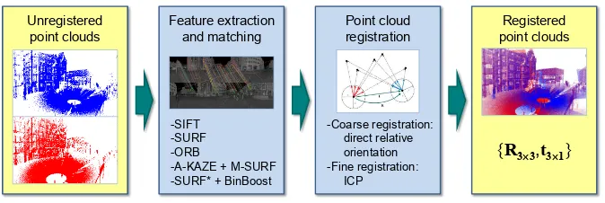
As shown in Figure 1, our framework for automatically aligning TLS point clouds consists of two major steps: (i) feature extrac-tion and matching and (ii) point cloud registration. The respective methods involved in these components are provided as well and described in the following subsections.
3.1 Keypoint Extraction and Matching
Generally, the performance of keypoint matching is an interplay of the applied keypoint detector and descriptor (Dahl et al., 2011). Hence, different keypoint detector-descriptor combinations may be applied and these may differ in their suitability, depending on the requirements of the respective application. Focusing on scan representations in the form of panoramic intensity images, where keypoint descriptors have to cope with significant changes in rotation and scale for changes in the scanner position, we only involve scale and rotation-invariant keypoint representations as listed in Table 1. More details on the respective keypoint detec-tors and descripdetec-tors are provided in the following.
Variant Detector Detector Descriptor Descriptor
type size / type / information
1 SIFT Blobs SIFT 128/ float / gradient
2 SURF Blobs SURF 64/ float / gradient
3 ORB Corners ORB 32/ binary / intensity
4 A-KAZE Blobs M-SURF 64/ float / gradient
5 SURF∗ Blobs BinBoost 32/ binary / gradient
Table 1. The keypoint detector-descriptor combinations involved in our framework.
3.1.1 SIFT: For keypoint detection, the Scale Invariant Fea-ture Transform (SIFT) (Lowe, 1999; Lowe, 2004) relies on con-volving the imageIand subsampled versions ofIwith Gaussian kernels of variable scale in order to derive the Gaussian space. Subtracting neighboring images in the Gaussian scale-space results in the Difference-of-Gaussian (DoG) pyramid, where extrema in a(3×3×3)neighborhood correspond to keypoint candidates. These keypoint candidates are improved by an inter-polation based on a 3D quadratic function in the scale-space in order to obtain subpixel accurate locations in image space. Fur-thermore, those keypoint candidates with low contrast which are sensitive to noise as well as those keypoint candidates located along edges which can hardly be distinguished from each other are discarded.
In the next step, each keypoint is assigned its dominant orien-tation which results for the respective scale by considering the local gradient orientations weighted by the respective magnitude
as well as a Gaussian centered at the keypoint. Subsequently, the local gradient information is rotated according to the domi-nant orientation in order to achieve a rotation invariant keypoint descriptor. The descriptor itself is derived by splitting the local neighborhood into4×4subregions. For each of these subre-gions, an orientation histogram with8angular bins is derived by accumulating the gradient orientations weighted by the respec-tive magnitude as well as a Gaussian centered at the keypoint. The concatenation of all histogram bins and a subsequent nor-malization yield the final128-dimensional SIFT descriptor. For deriving feature correspondences, SIFT descriptors are typically compared by considering the ratio of Euclidean distances of a SIFT descriptor belonging to a keypoint in one image to the near-est and second nearnear-est SIFT descriptors in the other image. This ratio indicates the degree of similarity and thus the distinctiveness of matched features.
3.1.2 SURF: Speeded-Up Robust Features (SURF) (Bay et al., 2006; Bay et al., 2008) are based on a scale-space represen-tation of the Hessian matrix which is approximated with box fil-ters, so that the elements of the Hessian matrix may efficiently be evaluated at a very low computational cost using integral images. Thus, distinctive features in an image correspond to locations in the scale-space where the determinant of the approximated Hes-sian matrix reaches a maximum in a(3×3×3)neighborhood. The detected maxima are then interpolated in order to obtain sub-pixel accurate locations in image space.
Similar to SIFT, a dominant orientation is calculated for each keypoint. For this purpose, the Haar wavelet responses in x -andy-direction within a circular neighborhood are weighted by a Gaussian centered at the keypoint and represented in a new 2D coordinate frame. Accumulating all responses within a sliding orientation window covering60◦
yields a local orientation vec-tor, and the orientation vector of maximum length indicates the dominant orientation. For obtaining a rotation invariant keypoint descriptor, the local gradient information is rotated according to the dominant orientation. Then, the local neighborhood is di-vided into4×4subregions and, for each subregion, the Haar wavelet responses inx′
- andy′
-direction are weighted by a Gaus-sian centered at the keypoint. The concatenation of the sum of Haar wavelet responses inx′
- andy′
-direction as well as the sum of absolute values of the Haar wavelet responses inx′
- andy′ -direction for all subregions and a subsequent normalization yield the final 64-dimensional SURF descriptor. The comparison of SURF descriptors is the same as for SIFT descriptors.
3.1.3 ORB: The approach presented with the Oriented FAST and Rotated BRIEF (ORB) detector and descriptor (Rublee et al., 2011) represents a combination of a modified FAST detector and a modified BRIEF descriptor.
The Features from Accelerated Segment Test (FAST) detector (Rosten and Drummond, 2005) analyzes each pixel(x, y)of an imageI and takes into account those pixels located on a sur-rounding Bresenham circle. The intensity values corresponding to those pixels on the surrounding Bresenham circle are com-pared to the intensity valueI(x, y). Introducing a thresholdt, the investigated pixel(x, y)represents a candidate keypoint if a certain number of contiguous pixels have intensity values above I(x, y) +tor belowI(x, y)−t. A subsequent non-maximum suppression avoids keypoints at adjacent pixels. The modifica-tion resulting in the ORB detector is based on employing a scale pyramid of the image, producing FAST features at each level in the pyramid and adding an orientation component to the standard FAST detector.
Unregistered
Figure 1. The proposed framework for keypoint-based point cloud registration and the involved methods for each component.
strings from image patches. In this context, the individual bits are obtained from a set of binary tests based on comparing the inten-sities of pairs of points along specific lines. The modification re-sulting in the ORB descriptor consists of steering BRIEF accord-ing to the orientation of keypoints and thus derivaccord-ing a rotation-aware version of the standard BRIEF descriptor. The similarity of such binary descriptors can be evaluated by using the Ham-ming distance, which is very efficient to compute.
3.1.4 A-KAZE and M-SURF: Instead of the Gaussian scale-space of an image, using a non-linear scale-scale-space may be fa-vorable as Gaussian blurring does not respect the natural bound-aries of objects and smoothes to the same degree both details and noise, reducing localization accuracy and distinctiveness of fea-tures (Alcantarilla et al., 2012). Such a non-linear scale-space may for instance be derived by using efficient additive opera-tor splitting (AOS) techniques and variable conductance diffusion which have been employed for detecting KAZE features (Alcan-tarilla et al., 2012). The nonlinear diffusion filtering, in turn, makes blurring locally adaptive to the image data and thus re-duces noise while retaining object boundaries. However, AOS schemes require solving a large system of linear equations to ob-tain a solution. In order to increase computational efficiency, it has been proposed to build a nonlinear scale-space with fast explicit diffusion (FED) and thereby embed FED schemes in a pyramidal framework with a fine-to-coarse strategy. Using such a non-linear scale-space, Accelerated KAZE (A-KAZE) features (Alcantarilla et al., 2013) may be extracted by finding maxima of the scale-normalized determinant of the Hessian matrix, where the first and second order derivatives are approximated by means of Scharr filters, through the nonlinear scale-space. After a subse-quent non-maximum suppression, the remaining keypoint candi-dates are further refined to subpixel accuracy by fitting a quadratic function to the determinant of the Hessian response in a(3×3) image neighborhood and finding its maximum.
In the next step, scale and rotation invariant feature descriptors may be derived by estimating the dominant orientation of the key-point in analogy to the SURF descriptor and rotating the local image neighborhood accordingly. Based on the rotated neighbor-hood, using the Modified-SURF (M-SURF) descriptor (Agrawal et al., 2008) adapted to the non-linear scale-space has been pro-posed which, compared to the original SURF descriptor, intro-duces further improvements due to a better handling of descriptor boundary effects and due to a more robust and intelligent two-stage Gaussian weighting scheme (Alcantarilla et al., 2012).
3.1.5 SURF∗
and BinBoost: Finally, we also involve a key-point detector-descriptor combination which consists of applying a modified variant of the SURF detector and using the BinBoost descriptor (Trzcinski et al., 2012; Trzcinski et al., 2013). In com-parison to the standard SURF detector (Bay et al., 2006; Bay et al., 2008), the modified SURF detector, denoted as SURF∗
in our
paper, iterates the parameters of the SURF detector until a desired number of features is obtained2. Once appropriate parameters have been derived, the dominant orientation for each keypoint is calculated and used to rotate the local image neighborhood in or-der to allow a scale and rotation invariant feature description.
As descriptor, the BinBoost descriptor (Trzcinski et al., 2012; Trzcinski et al., 2013) is used which represents a learned low-dimensional, but highly distinctive binary descriptor, where each dimension (each byte) of the descriptor is computed with a binary hash function that was sequentially learned using Boosting. The weights as well as the spatial pooling configurations of each hash function are learned from training sets consisting of positive and negative gradient maps of image patches. In general, Boosting combines a number of weak learners in order to obtain a single strong classifier. In the context of the BinBoost descriptors, the weak learners are represented by gradient-based image features that are directly applied to intensity image patches. During the learning stage of each hash function, the Hamming distance be-tween image patches is optimized, i.e. it is decreased for positive and increased for negative patches. Since, in our experiments, the BinBoost descriptor with32bytes worked best, we only re-port the results for this descriptor version.
3.2 Point Cloud Registration
Introducing a superscriptjwhich indicates the respective scanS j
and a subscriptiwhich indicates the respective feature
correspon-dence, the forward-projection ofncorresponding 2D keypoints x1
i ↔x
2
i between the panoramic intensity images of two scans
S1andS2according to the respective range information yields sparse point sets of corresponding 3D pointsX1
i ↔X
2
i.
Classi-cally, the task of keypoint-based point cloud registration is solved by estimating the rigid Euclidean transformation between the two sets of corresponding 3D points, i.e. a rigid-body transformation of the form
and a translation vectort21 ∈
R3
(where the superscript indicates the target coordinate frame and the subscript indicates the current coordinate frame). Accord-ingly, the rigid-body transformation is estimated in object space.
As omnidirectional representations in the form of panoramic range and intensity images are available, we propose to estimate the transformation in observation space, i.e. we intend to find the relative orientation between consecutive scans directly. For this purpose, we apply a spherical normalizationN(·)which normal-izes 3D pointsXj
igiven in the local coordinate frame of scanSj
to unit length and thus yields the so-called bearing vectors
vj
that simply represent the direction of a 3D pointXj
i w.r.t. the
local coordinate frame of the laser scanner. Thus, the task of point cloud registration may be transferred to the task of finding the transformation of one set of bearing vectors to another. In photogrammetry and computer vision, this is known as relative orientation and the transformation is encoded both in the essen-tial matrixEand the fundamental matrixF, respectively. The relationship between both is given by:
F=K−TEK−1
=K−T[t]
×RK
−1
(3)
where[t]×denotes the skew symmetric matrix of the translation and Krepresents a calibration matrix. For omnidirectional or panoramic images, the standard fundamental matrixFcannot be estimated, since it encapsulates the calibration matrixKwhich, in turn, is based on perspective constraints that do not hold in the omnidirectional case. The essential matrixE, however, is inde-pendent of the camera type and may hence be used to estimate the transformation between two panoramic images.
In general, at least five points are necessary to calculate a finite number of solutions forE (Philip, 1998). Various algorithms for the estimation of the essential matrixEexist, ranging from the minimal five-point algorithms (Nist´er, 2004; Stew´enius et al., 2006) to the six-point (Pizarro et al., 2003), the seven-point (Hart-ley and Zisserman, 2008), and the eight-point (Longuet-Higgins, 1987) algorithms. As observed in seminal work (Stew´enius et al., 2006; Rodehorst et al., 2008) and verified by own experiments, the five-point solver of (Stew´enius et al., 2006) performs best in terms of numerical precision, special motions or scene character-istics and resilience to measurement noise. For this reason, we focus on the use of this algorithm in our paper.
3.2.1 Coarse registration: The input to our registration pro-cedure is represented by putative feature correspondences between 2D pointsxj
ithat are subsequently transformed to bearing vectors
vj
i by exploiting the respective range information. Since the 2D
pointsxj
iare localized with subpixel accuracy, a respective
bilin-ear interpolation is applied on the 2D scan grid in order to obtain the respective 3D coordinatesXj
i. Then, the essential matrixEis
estimated using Stew´enius’ five-point algorithm (Stew´enius et al., 2006) and thereby involving the RANSAC algorithm (Fischler and Bolles, 1981) for increased robustness. For this, we use the implementation of OpenGV (Kneip and Furgale, 2014). A subse-quent decomposition ofEyields the rotation matrixR2
1and the translation vectorˆt21(Hartley and Zisserman, 2008). Since the es-sential matrixEonly has five degrees of freedom, the translation vectorˆt2
1is only known up to a scalar factors, which is indicated by aˆsymbol. In order to recover the scale factors, the following is calculated over all inliers:
smedian= median
The median is used to diminish potential outliers that could still reside in the data. Finally, the direction vectorˆt2
1 is scaled by
smedianto get the final translationt 2
1=smedianˆt 2
1.
3.2.2 Fine registration: In order to remove those 3D points indicating potential outlier correspondences from the 3D point sets, we apply a simple heuristic. First, the point setX1
i is
trans-formed toXˆ2i using Equation 1 and the coarse estimates forR21 and t2
1. Then, the Euclidean distance between all correspond-ing 3D points is calculated and only those points with an Eu-clidean distance below1m are kept. To remove such heuristics, one could employ iterative reweighted least squares techniques or a RANSAC-based modification of the ICP algorithm.
The remaining 3D points of the sparse point sets are provided to a
standard ICP algorithm (Besl and McKay, 1992) which generally converges to the nearest local minimum of a mean square distance metric, where the rate of convergence is high for the first few iterations. Given an appropriate coarse registration delivering the required initial values forR2
1andt
2
1, even a global minimization may be expected. In our experiments, we apply an ICP-based fine registration and consider the result after10iterations.
4 EXPERIMENTAL RESULTS
In our experiments, we use a standard benchmark TLS dataset (Section 4.1) and focus on the performance of different methods for each component of the framework (Section 4.2). Additionally, we discuss the derived results w.r.t. pros and cons of the involved methods (Section 4.3).
4.1 Dataset
The involved TLS dataset3has been captured with a Riegl LMS-Z360i laser scanner in an area called “Holzmarkt” which is lo-cated in the historic district of Hannover, Germany. Accord-ing to (Brenner et al., 2008), the Riegl LMS-Z360i has a sAccord-ingle shot measurement accuracy of12mm and its field-of-view covers 360◦
×90◦
, while the measurement range reaches up to200m. Furthermore, the angular resolution is about0.12◦
and, thus, a full scan results in3000×750 = 2.25M scanned 3D points.
In total, the dataset consists of20scans of which12were taken with (approximately) upright scan head and8with a tilted scan head. The single scan positions for the upright scans have been selected systematically along a trajectory with a spacing of ap-proximately5m, whereas the scan positions for the tilted scans almost coincide with the scan position for an upright scan, and reference values for both position and orientation have been ob-tained by placing artificial markers in the form of retro-reflective cylinders in the scene and carrying out a manual alignment based on these artificial targets. Thus, errors in the range of a few mil-limeters may be expected. In our experiments, we consider the similarity between upright and tilted scans acquired at almost the same position as too high to allow a fair statement on the registra-tion accuracy obtained with our framework (since the respective errors w.r.t. the estimated scan position are significantly below the measurement accuracy of12mm), and hence we only use the upright scans (Figure 2).
Since both range and intensity information are recorded for each point on the discrete scan raster, we may easily characterize each scan with a respective panoramic range image and a respective panoramic intensity image, where each image has a size of3000× 750pixels. As the captured intensity information depends on the device, we adapt it via histogram normalization to the interval [0,255]in order to obtain8-bit gray-valued images.
4.2 Experiments
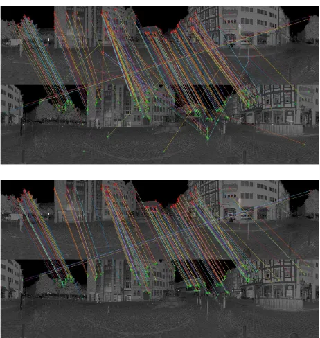
Our experiments focus on the successive pairwise registration of scan pairsPj ={Sj,Sj+1}withj = 1, . . . ,11. For this pur-pose, we apply the different methods for feature extraction as de-scribed in Section 3.1 and the registration scheme as dede-scribed in Section 3.2. We use the implementations provided in OpenCV 2.4 for SIFT, SURF and ORB, while we use the implementations provided with the respective paper for the other two keypoint detector-descriptor combinations. An example showing feature correspondences derived via the combination of an A-KAZE de-tector and an M-SURF descriptor is provided in Figure 3.
3This dataset and others have been released at
1 2 3 4
5 6 7 8 9 10 11 12
Figure 2. Map of the Hannover “Holzmarkt”: the position of buildings is visualized in dark gray and the scan positions for different scansSjare indicated with red spots. The scan IDs are
adapted according to (Brenner et al., 2008).
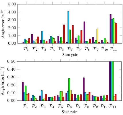
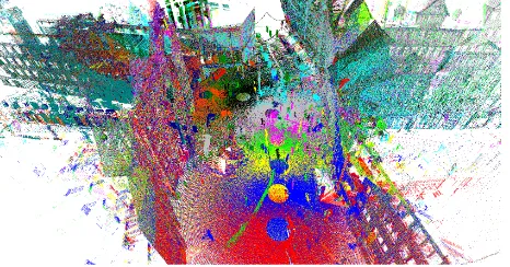
For evaluating the performance of our framework, the respective position and angle errors after coarse and fine registration are vi-sualized in Figure 4 and Figure 5. Thereby, the position error indicates the deviation of the estimated scan position from the reference values, whereas the angle error has been determined by transforming the estimated rotation matrix and the respective reference to Rodrigues vectors which, in turn, allow to derive an-gle errors as the difference of these Rodrigues vectors w.r.t. their length (Kneip and Furgale, 2014). Furthermore, we provide the number of correspondences used for coarse and fine registration in Figure 6 in order to quantify differences between the different methods for feature extraction and matching. For coarse regis-tration, we further provide the ratio of inliers w.r.t. all feature correspondences as well as the number of RANSAC iterations in Figure 7. In order to obtain an impression on the computational effort on a standard notebook (Intel Core i7-3630QM,2.4Ghz, 16GB RAM), the average processing times for different subtasks are provided in Table 2 as well as the expected time for the whole process of aligning two scans. Finally, we also provide a visual-ization of registered TLS scans in Figure 8.
Method tFEX[s] tFM[s] tCR[s] tFR[s] tΣ[s]
SIFT 3.055 10.479 0.084 0.012 16.684
SURF 0.644 0.414 0.081 0.022 1.805
ORB 0.138 2.023 0.015 0.021 2.336
A-KAZE + M-SURF 2.815 2.533 0.007 0.050 8.221
SURF∗+ BinBoost 2.423 0.067 0.025 0.013 4.950
Table 2. Average processing timestFEXfor feature extraction,
tFMfor feature matching,tCRfor coarse registration,tFRfor fine registration and average total timetΣrequired for automatically aligning two scans.
4.3 Discussion
The results provided in Figure 4 and Figure 5 reveal that the posi-tion errors after fine registraposi-tion are less than0.06m for almost all keypoint detector-descriptor combinations when considering the scan pairsP1, . . . ,P10, where the distance between the respec-tive scan positions is between4m and6m. Since the respective angle errors after fine registration are below0.15◦
with only a few exceptions, we may conclude that the presented method for coarse registration represents a competitive method in order to coarsely align the given scans, since a respective outlier rejection based on 3D distances is sufficient for an ICP-based fine regis-tration. The applicability of our method for coarse registration is even further motivated by the fact that the respective processing
Figure 3. Feature correspondences between the panoramic inten-sity images of scansS1 andS2 when using the combination of an A-KAZE detector and an M-SURF descriptor: all correspon-dences (top) vs. inlier corresponcorrespon-dences (bottom).
time is less than0.085s for the considered scan pairs (Table 2). Thus, we reach a total time of less than10s for the registration of the considered scan pairs for four of the five tested keypoint detector-descriptor combinations, and only the involved imple-mentation for SIFT is not that efficient. Note that the time for feature extraction is counted twice, since this task is required for both scans of a scan pair.
Considering the five involved keypoint detector-descriptor com-binations, we may state that A-KAZE + M-SURF and SURF∗
+ BinBoost tend to provide the best results after fine registration (Figure 4 and Figure 5). Note that only these combinations are also able to derive a suitable position and angle estimate for the last scan pairP11={S11,S12}, where the distance between the respective scan positions is approximately12m. The respective position errors for A-KAZE + M-SURF and SURF∗
+ BinBoost after fine registration are0.054m and0.085m, while the angle errors are 0.056◦
and 0.083◦
, respectively. In contrast, SIFT, SURF and ORB provide a position error of more than0.20m and an angle error of more than0.75◦
for that case.
In Figure 6, it becomes visible that the number of feature corre-spondences used for coarse registration is similar for SIFT, ORB and SURF∗
+ BinBoost, while it tends to be higher for SURF. For A-KAZE + M-SURF, even a significant increase of this num-ber may be observed across all12scan pairs. The increase in the number of involved feature correspondences for A-KAZE + M-SURF compared to the other keypoint detector-descriptor combi-nations is even more significant when considering fine registra-tion, where it is partially even more than twice as much as for the others. Based on these characteristics, an interesting trend becomes visible when considering the respective ratio of inliers during coarse registration. While the inlier ratio is comparable for SIFT and SURF, it is better for SURF∗
P1 P2 P3 P4 P5 P6 P7 P8 P9 P10P11
Figure 4. Position errors after the coarse registration (top) and af-ter the fine registration (bottom) of scan pairsPj={Sj,Sj+1}: SIFT (violet), SURF (cyan), ORB (green), A-KAZE + M-SURF (yellow), SURF∗
+ BinBoost (red).
combination A-KAZE + M-SURF not only increases the number of correspondences, but also the inlier ratio and, thus, the posi-tion and angle errors across all scan pairs tend to be the lowest for this combination (Figure 4 and Figure 5). For most of the scan pairs, the respective position error is even close or below the given measurement accuracy of12mm.
Finally, we may state that our framework is suited for both urban environments and scenes containing vegetation, and it does nei-ther depend on regular surfaces nor human interaction. The only limitation may be identified in the fact that feature correspon-dences have to be derived between the panoramic intensity im-ages derived for the respective scans. In this regard, we may gen-erally observe that the total number of feature correspondences decreases with an increasing distance between the respective scan positions and, accordingly, the quality of the registration results will decrease. However, this constraint holds for the other image-based approaches as well and is not specific for our framework.
5 CONCLUSIONS
In this paper, we have presented a novel framework for evaluat-ing the influence of different keypoint detector-descriptor combi-nations on the results of point cloud registration. While we in-volve five different approaches for extracting local features from the panoramic intensity images derived for the single scans, the registration process has been transferred from object space to ob-servation space by considering the forward-projection of putative feature correspondences and exploiting bearing vectors instead of the corresponding 3D points themselves. Our results clearly re-veal that replacing SIFT and SURF detectors and descriptors by more recent approaches significantly alleviates point cloud regis-tration in terms of accuracy, efficiency and robustness.
For future work, we plan to integrate more approaches for fea-ture extraction as well as more approaches for keypoint-based point cloud registration in our framework in order to objectively evaluate their performance on publicly available benchmark TLS datasets. In this context, it would also be desirable to point out chances and limitations of the different approaches w.r.t. different criteria specified by potential end-users, e.g. the spacing between adjacent scans or the complexity of the observed scene. Promis-ing results may be expected.
P1 P2 P3 P4 P5 P6 P7 P8 P9 P10P11
Figure 5. Average angle errors after the coarse registration (top) and after the fine registration (bottom) of scan pairsPj =
{Sj,Sj+1}: SIFT (violet), SURF (cyan), ORB (green), A-KAZE + M-SURF (yellow), SURF∗
+ BinBoost (red).
REFERENCES
Agrawal, M., Konolige, K. and Blas, M. R., 2008. CenSurE: center sur-round extremas for realtime feature detection and matching.Proceedings of the European Conference on Computer Vision, Vol. IV, pp. 102–115. Aiger, D., Mitra, N. J. and Cohen-Or, D., 2008. 4-points congruent sets for robust pairwise surface registration. ACM Transactions on Graphics
27(3), pp. 1–10.
Alcantarilla, P. F., Bartoli, A. and Davison, A. J., 2012. KAZE features.
Proceedings of the European Conference on Computer Vision, Vol. VI, pp. 214–227.
Alcantarilla, P. F., Nuevo, J. and Bartoli, A., 2013. Fast explicit diffusion for accelerated features in nonlinear scale spaces. Proceedings of the British Machine Vision Conference, pp. 13.1–13.11.
Arun, K. S., Huang, T. S. and Blostein, S. D., 1987. Least-squares fit-ting of two 3-D point sets. IEEE Transactions on Pattern Analysis and Machine Intelligence9(5), pp. 698–700.
Barnea, S. and Filin, S., 2007. Registration of terrestrial laser scans via image based features.The International Archives of the Photogrammetry, Remote Sensing and Spatial Information Sciences, Vol. XXXVI-3/W52, pp. 32–37.
Barnea, S. and Filin, S., 2008. Keypoint based autonomous registration of terrestrial laser point-clouds. ISPRS Journal of Photogrammetry and Remote Sensing63(1), pp. 19–35.
Bay, H., Ess, A., Tuytelaars, T. and Van Gool, L., 2008. Speeded-up ro-bust features (SURF).Computer Vision and Image Understanding110(3), pp. 346–359.
Bay, H., Tuytelaars, T. and Van Gool, L., 2006. SURF: speeded up robust features. Proceedings of the European Conference on Computer Vision, Vol. 1, pp. 404–417.
Besl, P. J. and McKay, N. D., 1992. A method for registration of 3-D shapes.IEEE Transactions on Pattern Analysis and Machine Intelligence
14(2), pp. 239–256.
Boehm, J. and Becker, S., 2007. Automatic marker-free registration of terrestrial laser scans using reflectance features. Optical 3-D Measure-ment TechniquesVIII, pp. 338–344.
Brenner, C., Dold, C. and Ripperda, N., 2008. Coarse orientation of ter-restrial laser scans in urban environments.ISPRS Journal of Photogram-metry and Remote Sensing63(1), pp. 4–18.
Calonder, M., Lepetit, V., Strecha, C. and Fua, P., 2010. BRIEF: binary robust independent elementary features. Proceedings of the European Conference on Computer Vision, Vol. IV, pp. 778–792.
Dahl, A. L., Aanæs, H. and Pedersen, K. S., 2011. Finding the best feature detector-descriptor combination. Proceedings of the International Con-ference on 3D Imaging, Modeling, Processing, Visualization and Trans-mission, pp. 318–325.
P1 P2 P3 P4 P5 P6 P7 P8 P9 P10P11 0
200 400 600 800 1,000
Scan pair
#
Correspondences
P1 P2 P3 P4 P5 P6 P7 P8 P9 P10P11
0 200 400 600 800 1,000
Scan pair
#
Correspondences
Figure 6. Number of feature correspondences used for the coarse registration (top) and for the fine registration (bottom) of scan pairs Pj = {Sj,Sj+1}: SIFT (violet), SURF (cyan), ORB (green), A-KAZE + M-SURF (yellow), SURF∗
+ BinBoost (red).
Gressin, A., Mallet, C., Demantk´e, J. and David, N., 2013. Towards 3D lidar point cloud registration improvement using optimal neighborhood knowledge. ISPRS Journal of Photogrammetry and Remote Sensing79, pp. 240–251.
Harris, C. and Stephens, M., 1988. A combined corner and edge detector.
Proceedings of the 4th Alvey Vision Conference, pp. 147–151.
Hartley, R. I. and Zisserman, A., 2008. Multiple view geometry in com-puter vision. University Press, Cambridge, UK.
Kneip, L. and Furgale, P., 2014. OpenGV: a unified and generalized ap-proach to real-time calibrated geometric vision.Proceedings of the IEEE International Conference on Robotics and Automation, pp. 1–8. Longuet-Higgins, H. C., 1987. A computer algorithm for reconstruct-ing a scene from two projections. In: Fischler, M. A. and Firschein, O. (Eds.),Readings in Computer Vision: Issues, Problems, Principles, and Paradigms. Morgan Kaufmann, San Francisco, USA, pp. 61–62. Lowe, D. G., 1999. Object recognition from local scale-invariant features.
Proceedings of the IEEE International Conference on Computer Vision, pp. 1150–1157.
Lowe, D. G., 2004. Distinctive image features from scale-invariant key-points.International Journal of Computer Vision60(2), pp. 91–110. Matas, J., Chum, O., Urban, M. and Pajdla, T., 2002. Robust wide base-line stereo from maximally stable extremal regions. Proceedings of the British Machine Vision Conference, pp. 36.1–36.10.
Nist´er, D., 2004. An efficient solution to the five-point relative pose prob-lem. IEEE Transactions on Pattern Analysis and Machine Intelligence
26(6), pp. 756–770.
Philip, J., 1998. Critical point configurations of the 5-, 6-, 7-, and 8-point algorithms for relative orientation. Technical Report TRITA-MAT-1998-MA-13, Department of Mathematics, Royal Institute of Technol-ogy, Stockholm, Sweden.
Pizarro, O., Eustice, R. and Singh, H., 2003. Relative pose estimation for instrumented, calibrated imaging platforms. Proceedings of Digital Image Computing Techniques and Applications, pp. 601–612.
Rodehorst, V., Heinrichs, M. and Hellwich, O., 2008. Evaluation of rela-tive pose estimation methods for multi-camera setups.The International Archives of the Photogrammetry, Remote Sensing and Spatial Informa-tion Sciences, Vol. XXXVII-B3b, pp. 135–140.
Rosten, E. and Drummond, T., 2005. Fusing points and lines for high performance tracking. Proceedings of the International Conference on Computer Vision, Vol. 2, pp. 1508–1515.
Rublee, E., Rabaud, V., Konolige, K. and Bradski, G., 2011. ORB: an efficient alternative to SIFT or SURF.Proceedings of the IEEE Interna-tional Conference on Computer Vision, pp. 2564–2571.
Rusinkiewicz, S. and Levoy, M., 2001. Efficient variants of the ICP algo-rithm.Proceedings of the International Conference on 3D Digital Imag-ing and ModelImag-ing, pp. 145–152.
Stew´enius, H., Engels, C. and Nist´er, D., 2006. Recent developments on direct relative orientation.ISPRS Journal of Photogrammetry and Remote Sensing60(4), pp. 284–294.
P1 P2 P3 P4 P5 P6 P7 P8 P9 P10P11
0.00 0.20 0.40 0.60 0.80 1.00
Scan pair
Inlier
ratio
P1 P2 P3 P4 P5 P6 P7 P8 P9 P10P11
0 40 80 120 160 200
Scan pair
#
RANSA
C
iterations
Figure 7. Inlier ratio (top) and number of RANSAC itera-tions (bottom) for the coarse registration of scan pairs Pj =
{Sj,Sj+1}: SIFT (violet), SURF (cyan), ORB (green), A-KAZE + M-SURF (yellow), SURF∗
+ BinBoost (red).
Figure 8. Aligned point clouds when using A-KAZE + M-SURF: the points belonging to different scansSjare encoded with
dif-ferent color.
Theiler, P. W., Wegner, J. D. and Schindler, K., 2013. Markerless point cloud registration with keypoint-based 4-points congruent sets. ISPRS Annals of the Photogrammetry, Remote Sensing and Spatial Information Sciences, Vol. II-5/W2, pp. 283–288.
Theiler, P. W., Wegner, J. D. and Schindler, K., 2014. Keypoint-based 4-points congruent sets – Automated marker-less registration of laser scans.
ISPRS Journal of Photogrammetry and Remote Sensing96, pp. 149–163. Trzcinski, T., Christoudias, M., Fua, P. and Lepetit, V., 2012. Learning image descriptors with the boosting-trick. Proceedings of the Annual Conference on Neural Information Processing Systems, Vol. 1, pp. 269– 277.
Trzcinski, T., Christoudias, M., Fua, P. and Lepetit, V., 2013. Boost-ing binary keypoint descriptors.Proceedings of the IEEE Conference on Computer Vision and Pattern Recognition, pp. 2874–2881.
Tuytelaars, T. and Mikolajczyk, K., 2008. Local invariant feature detec-tors: a survey.Foundations and Trends in Computer Graphics and Vision
3(3), pp. 177–280.
Umeyama, S., 1991. Least-squares estimation of transformation parame-ters between two point patterns. IEEE Transactions on Pattern Analysis and Machine Intelligence13(4), pp. 376–380.
Weinmann, M., 2013. Visual features – From early concepts to modern computer vision. In: Farinella, G. M., Battiato, S. and Cipolla, R. (Eds.),
Advanced Topics in Computer Vision. Advances in Computer Vision and Pattern Recognition, Springer, London, UK, pp. 1–34.
Weinmann, M. and Jutzi, B., 2011. Fully automatic image-based reg-istration of unorganized TLS data. The International Archives of the Photogrammetry, Remote Sensing and Spatial Information Sciences, Vol. XXXVIII-5/W12, pp. 55–60.